Do you have a V0 or SW, with a SKR Mini? Are you like me and Blargedy, and want to also measure your chamber temp for bragging reasons? Are you annoyed that the SKR Mini doesn't have any good thermistor ports?
Lets fix that, with a DS18B20 digital thermistor, via the Dallas one-wire protocol. These instructions are entirely for a Raspberry Pi. I'm sure other alt-Pi's work, but I have no idea how to make it work.
Supplies:
* DS18B20 digital thermistor. Non-affiliate link: https://smile.amazon.com/HiLetgo-DS18B20-Temperature-Stainless-Waterproof/dp/B00M1PM55K/ref=sr_1_4 . This is not the only one that will work, there are several listings that will show up if you search for "DS18B20" on Amazon or eBay in this form factor. Get the ones with the premade probe, not the bare sensors.
Step 1: Installing the Pi as an MCU in Klipper
All of this will be the instructions used to add the Pi as a secondary MCU in Klipper. If you have already done this (because you used an ADXL, for instance) you can skip to Step 2. These steps are lifted from Klipper's documentation, found at https://www.klipper3d.org/RPi_microcontroller.html .
First, SSH into your Pi. How to do this is outside the scope of this post. Run the following steps one at a time in the terminal:
Step 2: Enabling Dallas 1-wire
Add an overlay to the end of your boot config:
Step 3: Python script to enable Raspberry Pi pullup
The DS18B20 needs a pullup to work, and we can use software pullups in the Pi itself. The way I've found to do it is with a one-and-done Python script that executes on startup. SSH back in to the pi, and run the following (copy+paste the whole block, and run it in one shot):
If there are no errors, run the following command:
Add this line to the end of the file:
Step 4: Prepare the sensor itself
You must power the Pi down before doing this step. You run a real risk of breaking your Pi if you plug things into it while powered on!
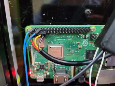
Thanks to Blargedy for the pictures! The pins we are using are the following in the GPIO header on the Pi:
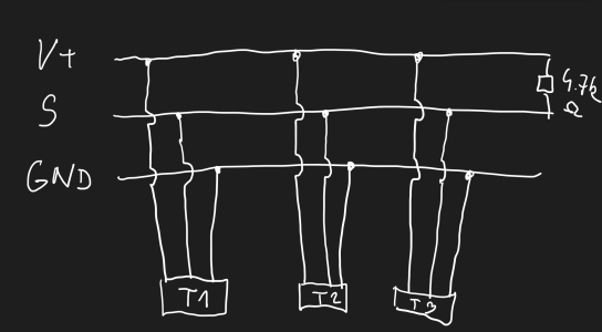
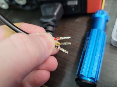
Crimp 3 Dupont-style connectors onto the wires, making sure the rear wings grip the insulation and the front wings tightly grip the wire itself:
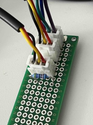
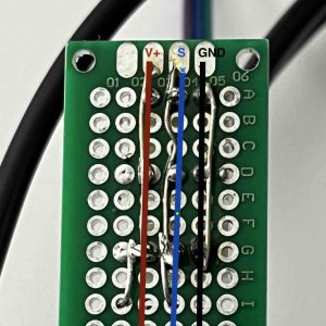
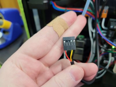
Insert the wires into a 1x5 header as shown:
Plug the header into your POWERED DOWN Pi as shown (the top blue wires are power in):
Step 5: Find the DS18B20
Power the machine back on and wait for the Pi to boot. Once it's running again, SSH back in, and run the following command to look for your temperature sensor:
You'll hopefully see something like:
The important part is the 28-xxxxxxxxx. That is the DS18B20 sensor on the bus. If you don't have anything that looks like that, something is wrong. Copy the whole ID (mine is "28-01191f2eaf2f", yours will be different), and add this entire section to your printer.cfg:
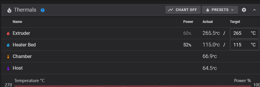
Do a firmware restart, and your new sensor should show up in your UI:
Lets fix that, with a DS18B20 digital thermistor, via the Dallas one-wire protocol. These instructions are entirely for a Raspberry Pi. I'm sure other alt-Pi's work, but I have no idea how to make it work.
Supplies:
* DS18B20 digital thermistor. Non-affiliate link: https://smile.amazon.com/HiLetgo-DS18B20-Temperature-Stainless-Waterproof/dp/B00M1PM55K/ref=sr_1_4 . This is not the only one that will work, there are several listings that will show up if you search for "DS18B20" on Amazon or eBay in this form factor. Get the ones with the premade probe, not the bare sensors.
Step 1: Installing the Pi as an MCU in Klipper
All of this will be the instructions used to add the Pi as a secondary MCU in Klipper. If you have already done this (because you used an ADXL, for instance) you can skip to Step 2. These steps are lifted from Klipper's documentation, found at https://www.klipper3d.org/RPi_microcontroller.html .
First, SSH into your Pi. How to do this is outside the scope of this post. Run the following steps one at a time in the terminal:
Code:
sudo service klipper stop
sudo cp "~/klipper/scripts/klipper-mcu-start.sh" /etc/init.d/klipper_mcu
sudo update-rc.d klipper_mcu defaults
cd ~/klipper
make menuconfig      (here, set "Microcontroller Architecture" to "Linux process", save and exit)
make flash
sudo service klipper start
Step 2: Enabling Dallas 1-wire
Add an overlay to the end of your boot config:
Code:
echo "dtoverlay=w1-gpio" | sudo tee -a /boot/config.txt
sudo reboot
Step 3: Python script to enable Raspberry Pi pullup
The DS18B20 needs a pullup to work, and we can use software pullups in the Pi itself. The way I've found to do it is with a one-and-done Python script that executes on startup. SSH back in to the pi, and run the following (copy+paste the whole block, and run it in one shot):
Code:
echo '#!/usr/bin/python
import RPi.GPIO as GPIO
GPIO.setmode(GPIO.BCM)
GPIO.setup(4, GPIO.IN, pull_up_down=GPIO.PUD_UP)' > ~/ds18b20.py
chmod +x ~/ds18b20.py
sudo ./ds18b20.py
If there are no errors, run the following command:
sudo crontab -e
Add this line to the end of the file:
@reboot /home/pi/ds18b20.py
Step 4: Prepare the sensor itself
You must power the Pi down before doing this step. You run a real risk of breaking your Pi if you plug things into it while powered on!
Thanks to Blargedy for the pictures! The pins we are using are the following in the GPIO header on the Pi:

Crimp 3 Dupont-style connectors onto the wires, making sure the rear wings grip the insulation and the front wings tightly grip the wire itself:

Insert the wires into a 1x5 header as shown:

Plug the header into your POWERED DOWN Pi as shown (the top blue wires are power in):

Step 5: Find the DS18B20
Power the machine back on and wait for the Pi to boot. Once it's running again, SSH back in, and run the following command to look for your temperature sensor:
ls /sys/bus/w1/devices/
You'll hopefully see something like:
Code:
pi@fluiddpi:~ $ ls /sys/bus/w1/devices/
28-01191f2eaf2f  w1_bus_master1
The important part is the 28-xxxxxxxxx. That is the DS18B20 sensor on the bus. If you don't have anything that looks like that, something is wrong. Copy the whole ID (mine is "28-01191f2eaf2f", yours will be different), and add this entire section to your printer.cfg:
Code:
[mcu rpi]
serial: /tmp/klipper_host_mcu

[temperature_sensor chamber]
sensor_type: DS18B20
sensor_mcu: rpi
serial_no: 28-01191f2eaf2f     ; you MUST use your own ID here
Do a firmware restart, and your new sensor should show up in your UI:

Last edited:


