What's new
VORON Design

Register a free account today to become a member! Once signed in, you'll be able to participate on this site by adding your own topics and posts, as well as connect with other members!

Attention regarding the Formbot 2.4 "Pro" (R1) kit!

shiftingtech

Well-known member
Staff member
Moderator
Trusted Advisor
Voron Owner
The wiring is incorrect on Formbot's wiring guide and will cause serious damage!
The included wiring for ports Diag7 (PG15) and Probe (PB7) contains errors which will destroy your electronics. Before powering on your Formbot 2.4 "Pro" kit, please review the information below

The Problem
1. The cable labelled Board-PG15 to PCB-ABL contains a wire which connects 24V (Breakout board) to 3.3V or 5V (Octopus). As soon as this is powered, it will cause damage to the Octopus, and likely any pi that is connected as well.
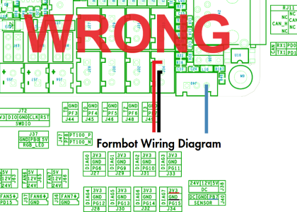
bad.pngwire.png
2. The unlabelled wire (single blue wire), and the cable from part 1 are swapped.

The Solution
1. Remove the red wire from the Board-PG15 cable entirely. It is not required. Please make sure to remove it entirely at both ends, or at least tape it off so it isn't wandering around loose in your electronics bay
2. Swap the Black cable, and the blue cable at the octopus.
good.png
 
The wiring is incorrect on Formbot's wiring guide and will cause serious damage!
The included wiring for ports Diag7 (PG15) and Probe (PB7) contains errors which will destroy your electronics. Before powering on your Formbot 2.4 "Pro" kit, please review the information below

The Problem
1. The cable labelled Board-PG15 to PCB-ABL contains a wire which connects 24V (Breakout board) to 3.3V or 5V (Octopus). As soon as this is powered, it will cause damage to the Octopus, and likely any pi that is connected as well.
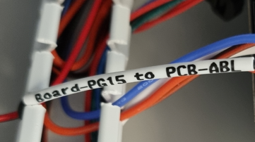
View attachment 3799View attachment 3803
2. The unlabelled wire (single blue wire), and the cable from part 1 are swapped.

The Solution
1. Remove the red wire from the Board-PG15 cable entirely. It is not required. Please make sure to remove it entirely at both ends, or at least tape it off so it isn't wandering around loose in your electronics bay
2. Swap the Black cable, and the blue cable at the octopus.
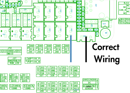
View attachment 3802
If you have any Questions regarding this, please ask in the voron_2_questions Channel
Edit: On VORON Discord https://discord.com/invite/vorondesign
 
Last edited by a moderator:
A lot of people are asking "do I really need to remove the red wire".

Here is the logic behind that recommendation, so you may make your own, informed decisions.

1. The red wire serves no useful purpose. 24v power is provided to the breakout board from different source (the he0 port)

2. The red wire plugged into the endstop port will destroy things.

3. The red wire will not actually destroy things plugged into the probe port, as long as the probe port power jumper is set to 24v

4. The red wire in the probe port will destroy things if the probe power jumper is set to 5v or 12v

Based on these points, I believe it is best practice to remove the wire, to avoid potential problems. For example, imagine a couple of years from now, you want to try out lower voltage probe. It would be perfectly reasonable to try to move the jumper, leading to a nasty surprise.
 
Last edited:
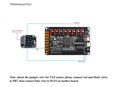
Sorry for the falsely labeled wire issue, the supplier sticked the label onto red wire mistakenly, it should have been sticked onto blue wire originally. we just found the issue recently and added correct label on the bag of cable. meanwhile, updated the wiring instruction as below: https://drive.google.com/file/d/19wdkwaP-MP6JrulkZ-r0Kav1kbvxzPzk/view
if you burnt down the board due to this issue, welcome to contact us for replacement freely. sorry for the confusion and trouble. (FORMBOT 3D Official)
0102-1.jpg
 

Attachments

  • 0102-2.jpg
    0102-2.jpg
    54.4 KB · Views: 324
Last edited:
I have destroyed more than one board due to this problem.
Formbot is working on getting me a replacements but I was thinking of trying to repair the boards for use on another project.
Does anyone know which components are typically destroyed and if they can be replaced?
The smoke came from one area of the board and I can see that the U11 IC is fried. I can see the damage.
I don't know what the component is or if other components would be damaged as well.
Btt has schematics on github, so it should be possible to identify that component.


However, literally everything that touches the 5v supply is likely damaged, so that's pretty far reaching, even if only the one component actually smoked. Personally, I would be very wary of attempting repair.
 
Thanks for the feedback. I'd basically came to the same conclusion after thinking about it a bit more. Even if I did the obvious repairs I'd never trust it for reliability.
 
The Formbot 2.4 R2 Pro kit fixes this I think. The kit comes with a Bigtreetech Manta M8P v1.1 motherboard but thank you for the warning.
 
Top