What's new
VORON Design

Register a free account today to become a member! Once signed in, you'll be able to participate on this site by adding your own topics and posts, as well as connect with other members!

CAN umbilical order lengths (chainflex, etc)

ZeroBrain

Member
What is a safe by-the-foot (or by-the-meter) length to order for a 250, 300, 250 build? This stuff is expensive, would be nice not to over-order.
 
If you have built it already, you could just take a measurement with a piece of ptfe tube or wire.
 
I went to the Voron Design Website at https://docs.vorondesign.com/build/electrical/V2_gantry_wires.html#lengths and bought the length for my build size.

When building I cut the length of the cable to fit my routing path. Usually I am very good at documenting the lengths but I can not find that information for my CAN bus.

I did however document how I wired up the CAN bus toolhead board and the lengths of cable I used for that build.

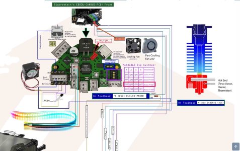
In this picture you see colored lines for wiring with an attached number to the colored line. The attached number is the length of the interconnecting wire in millimeters:

Interface Cable Diagram.69.jpg
 
Last edited:
The "exposed" length of my umbilical for my V2.4r2 300mm is 58 cm. My umbilical is mounted on my toolhead and on the top of the A motor plate.

I would buy double what you think you need so that you have some "play" and to account for some "waste" as you wire up the connectors...
 
other remark. the second piece PCB with LEDs the part cooling fan 90 degree dupont connector should face down and not up. usually the wire for the part cooling fan cross the PCB for behind and not in this case because you want to poke some holes in the fan and let the LEDs shine.
 
Gotta link to where you are getting it and which kind? Are you getting it directly from Igus?
 
Gotta link to where you are getting it and which kind? Are you getting it directly from Igus?
I used IGUS Chainflex "CF113-018-D" for my umbilical cable (GND to shield) [URL: https://www.igus.com/product/1120?artNr=CF113-001-D] the two extra wires where used
for the Euclid Probe Signal and the X-endstop Signal (both shielded) to run them back to the motherbaord so that the
endstop signals would be on the same mcu as their corresponding motor signals.

I used IGUS Chaninflex "CF113-007-D" on all my Z motors (GND to shield) - URL:https://dfh.fm/products/igus-chainflex%C2%AE-cf113-007-d?_pos=3&_sid=3370d111f&_ss=r
 
Hey @GadgetAngel can you please go into a bit more detail how you connected the little 5 V fan please? :)
I went to the Voron Design Website at https://docs.vorondesign.com/build/electrical/V2_gantry_wires.html#lengths and bought the length for my build size.

When building I cut the length of the cable to fit my routing path. Usually I am very good at documenting the lengths but I can not find that information for my CAN bus.

I did however document how I wired up the CAN bus toolhead board and the lengths of cable I used for that build.
 
Hey @GadgetAngel can you please go into a bit more detail how you connected the little 5 V fan please? :)
I documented the fan hookup for the EBB36 on my "wiring harness" diagram. The "wiring harness" diagram is located at https://forum.vorondesign.com/threads/my-modified-ldo-300-kit-build-log-updated-all-the-time.66/#post-678

But here is a close up of it:

EBB36 Fan Hookup.jpg

Further instructions can be found at https://github.com/HyperToxic33/EBB-Fan-Control#ebb-fan-control

That is where I found the information for my build.

You can find my full build log at
https://forum.vorondesign.com/threa...t-build-log-updated-all-the-time.66/#post-342
 
Top