kubik
Active member
Hi,
I am sure that by now, you have most probably heard about the venerable CANBUS. Less wires, umbilicals galore; but more headaches with yet another thing to learn. Wouldn't it be great if you could get similar benefits without all of the hassle? Well, do I have a thing for you! But first, let me explain how we got here.
From what I gather, CAN has sprung up in our circles as it *theoretically* fits the bill. Since CAN is a bus architecture, you should be able to run a single cable (the bus) and hook devices up to it. Practically, it is my belief, this promise has not fully materialised. Here are a few reasons why I think it is so:
- there are no T connectors available (TODO: footnote about bulky car ones no one uses)
- virtually all of the boards are designed as terminal nodes, i.e. you do not have a second connector to continue the bus going further along
- basically everyone who setups CAN does so to be able to run a single thing -- the toolhead board.
The last point is my main gripe with the way we in the community use CAN currently. That's why I would like to introduce another option --- USB.
There are a few quite nice advantages to using USB, namely:
- the majority of the people already have it AND know how to use it. Virtually all of the boards that we use in our printers are connected either via native USB or USB-to-serial
- connected to the previous point, there is no particular setup required, it is PnP (Plug & Play).
- another connected point - cheaper because we do not need another board, we probably have spare USB ports.
- it brings the same major advantage that people like about CAN --- only 4 wires are required
Before naming the disadvantages, I would like to first state and try to debunk a few myths that people in our community believe about USB. I won't be mentioning any names, but at least one member of the Voron team was repeating these claims during discussions that I have witnessed. I believe it was being said in good will, in order to not let people go through uncharted waters. However, these claims are being *presented* as if they were absolute facts, which then through the word of mouth makes them into ground truths. In no particular order:
1. You need more wires for USB than for CAN
- People usually thought that you need to run a USB cable + power wires to a board to use it. This is probably due to their experiences with printer mainboards and their confusion about USB, the protocol, and USB, the cable. Theoretically, you would indeed need 4 wires for USB + 2 power wires. Practically, you can safely get away with using only four wires, similar to CANs VCC/GND/H/L, you can have VCC/GND/D+/D- [0]
2. USB cables are not motion rated
Once again, this stems from confusing USB, the cable/connector, and USB, the protocol. You can run the USB protocol over a shielded, motion-rated cable just fine. In addition, I have talked with a surprising number of people who just straight-up run USB cables to their toolheads. It has been working for them for a couple of hundred hours of printing so far. Whilst I would not recommend doing this, it seems to be a surprisingly viable strategy. The disadvantage here is that the USB connectors on the toolhead boards are usually surface mounted and could rip off if you do not fix the umbilical cable correctly so that it does not move.
3. It won't work because it is not up to USB spec/because of signal reflections/etc.
Unfortunately, I am no electrical engineer; I am a mere programmer with an interest in electronics. These issues have been brought up by people who claim to be electrical engineers. I have no reason to doubt their credentials or the truthfulness of these claims. However, the reality is often different from the theory and USB is a shining example of this. The USB specification is a mish-mash of the spec writers trying to lay down some ground rules whilst simultaneously trying to describe whatever the hell people were doing with USB out in the wild. Yes, the spec calls for a shielded cable. Are the majority of USB cables in the wild shielded properly? No --- but they work just fine. I won't be making a fool of myself by trying to talk about signal reflections or EMI, but the gist of what I would like to say is --- if it reliably works, do these theoretical problems matter? Should they be stopping us from experimenting with it?
With that out of the way, here are a few disadvantages that I could come up with. If you have any, please let me know.
- If your Pi is powered from a different power supply than the board you are trying to talk to, there could be problems. I believe that this is solvable by tying the grounds of the different power supplies together.
- If you are using a Pi Zero, you could be short on USB ports - already a problem currently and rather easily solvable with a hub
- Theoretically, you need longer wires, as USB is a point-to-point bus. Practically, we wire CAN similarly, so I don't think this would be a problem.
- Less noise immunity for longer runs compared to CAN. This might be a problem with bigger printers where the runs can get up to 2m in length, but if you use a well shielded cable, it should be fine. A bit of a chicken-and-an-egg problem --- if USB becomes more popular, there will be specialised cables available.
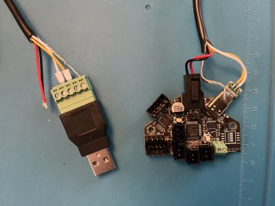
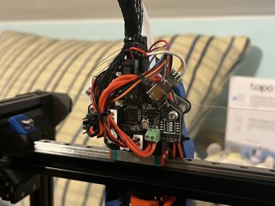
I am currently testing this on my V0 toolhead. I have been printing without any problems with my ghetto testing cable (it is shielded, but not that well - 1$/m recommendation from hartk) for at least a 100h. Pictures are of my testing setup. As you can see, it is really simple, uses easily available, cheap parts and could be spliced up with whatever USB cable you have at home; I just happened to have the USB screw terminal and USB-C connectors on hand.
I would like this post to start a discussion in regards to this topic. I am eager to hear your opinions and experiences.
Footnotes and references:
[0] You can share the power supply ground and the USB ground and omit the USB VBUS (5V) line, leaving you with only 4 wires that you need.
// EDIT1: Removed redundant text
I am sure that by now, you have most probably heard about the venerable CANBUS. Less wires, umbilicals galore; but more headaches with yet another thing to learn. Wouldn't it be great if you could get similar benefits without all of the hassle? Well, do I have a thing for you! But first, let me explain how we got here.
From what I gather, CAN has sprung up in our circles as it *theoretically* fits the bill. Since CAN is a bus architecture, you should be able to run a single cable (the bus) and hook devices up to it. Practically, it is my belief, this promise has not fully materialised. Here are a few reasons why I think it is so:
- there are no T connectors available (TODO: footnote about bulky car ones no one uses)
- virtually all of the boards are designed as terminal nodes, i.e. you do not have a second connector to continue the bus going further along
- basically everyone who setups CAN does so to be able to run a single thing -- the toolhead board.
The last point is my main gripe with the way we in the community use CAN currently. That's why I would like to introduce another option --- USB.
There are a few quite nice advantages to using USB, namely:
- the majority of the people already have it AND know how to use it. Virtually all of the boards that we use in our printers are connected either via native USB or USB-to-serial
- connected to the previous point, there is no particular setup required, it is PnP (Plug & Play).
- another connected point - cheaper because we do not need another board, we probably have spare USB ports.
- it brings the same major advantage that people like about CAN --- only 4 wires are required
Before naming the disadvantages, I would like to first state and try to debunk a few myths that people in our community believe about USB. I won't be mentioning any names, but at least one member of the Voron team was repeating these claims during discussions that I have witnessed. I believe it was being said in good will, in order to not let people go through uncharted waters. However, these claims are being *presented* as if they were absolute facts, which then through the word of mouth makes them into ground truths. In no particular order:
1. You need more wires for USB than for CAN
- People usually thought that you need to run a USB cable + power wires to a board to use it. This is probably due to their experiences with printer mainboards and their confusion about USB, the protocol, and USB, the cable. Theoretically, you would indeed need 4 wires for USB + 2 power wires. Practically, you can safely get away with using only four wires, similar to CANs VCC/GND/H/L, you can have VCC/GND/D+/D- [0]
2. USB cables are not motion rated
Once again, this stems from confusing USB, the cable/connector, and USB, the protocol. You can run the USB protocol over a shielded, motion-rated cable just fine. In addition, I have talked with a surprising number of people who just straight-up run USB cables to their toolheads. It has been working for them for a couple of hundred hours of printing so far. Whilst I would not recommend doing this, it seems to be a surprisingly viable strategy. The disadvantage here is that the USB connectors on the toolhead boards are usually surface mounted and could rip off if you do not fix the umbilical cable correctly so that it does not move.
3. It won't work because it is not up to USB spec/because of signal reflections/etc.
Unfortunately, I am no electrical engineer; I am a mere programmer with an interest in electronics. These issues have been brought up by people who claim to be electrical engineers. I have no reason to doubt their credentials or the truthfulness of these claims. However, the reality is often different from the theory and USB is a shining example of this. The USB specification is a mish-mash of the spec writers trying to lay down some ground rules whilst simultaneously trying to describe whatever the hell people were doing with USB out in the wild. Yes, the spec calls for a shielded cable. Are the majority of USB cables in the wild shielded properly? No --- but they work just fine. I won't be making a fool of myself by trying to talk about signal reflections or EMI, but the gist of what I would like to say is --- if it reliably works, do these theoretical problems matter? Should they be stopping us from experimenting with it?
With that out of the way, here are a few disadvantages that I could come up with. If you have any, please let me know.
- If your Pi is powered from a different power supply than the board you are trying to talk to, there could be problems. I believe that this is solvable by tying the grounds of the different power supplies together.
- If you are using a Pi Zero, you could be short on USB ports - already a problem currently and rather easily solvable with a hub
- Theoretically, you need longer wires, as USB is a point-to-point bus. Practically, we wire CAN similarly, so I don't think this would be a problem.
- Less noise immunity for longer runs compared to CAN. This might be a problem with bigger printers where the runs can get up to 2m in length, but if you use a well shielded cable, it should be fine. A bit of a chicken-and-an-egg problem --- if USB becomes more popular, there will be specialised cables available.
I am currently testing this on my V0 toolhead. I have been printing without any problems with my ghetto testing cable (it is shielded, but not that well - 1$/m recommendation from hartk) for at least a 100h. Pictures are of my testing setup. As you can see, it is really simple, uses easily available, cheap parts and could be spliced up with whatever USB cable you have at home; I just happened to have the USB screw terminal and USB-C connectors on hand.
I would like this post to start a discussion in regards to this topic. I am eager to hear your opinions and experiences.
Footnotes and references:
[0] You can share the power supply ground and the USB ground and omit the USB VBUS (5V) line, leaving you with only 4 wires that you need.
// EDIT1: Removed redundant text