3dCase
Well-known member
Hey fellow klipper captains and main_sailors,
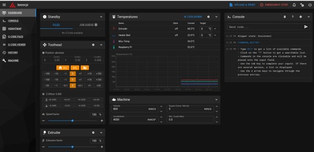
I have taken the plunge, because I got so fed up with all the trouble I had, and started my own klipper build. Using a RPI4, Octopus V1.1 and additionally a piggyback TFT50 screen from BTT on the RPI.
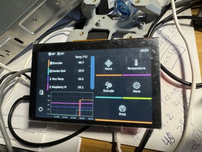
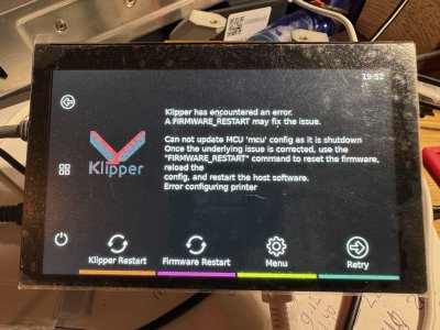
After the initial trouble with the startup hanging on some login prompt, I mean on the monitor that displays the RPI OS starting up, I found that I needed to install KlipperScreen as well. Once that was out of the way I got several other errors, off course, but picked them off one by one until finally I have a running RPI with Klipper and without error messages.
I only hung some thermistors I had off the Octopus in order not to get the out of range temperature errors, so that is why the extruder temp is showing high. But that is an easy fix once I hang the real stuff on the MCU.
Well happy with how this is going. I had huge trepidation before starting but it went smooth enough. It helps to have a brother on hand who is a linux wizzard and dreams those codes, but also with the help of the very friendly folk on the klipper discourse I got to where I am now.
The idea is to start my machine with basic umbilical and the cpap fan, and once that is working as it should I will go the one step further and use the canbus to lighten up the umbilical.
Here is hoping everything will be as smooth as it was till now, fingers crossed.
photos did not load up in the right order so you have to puzzle a bit
My desk has been looking like a hacker station for almost a week now, the wife started complaining


