What's new
VORON Design

Register a free account today to become a member! Once signed in, you'll be able to participate on this site by adding your own topics and posts, as well as connect with other members!

New 3D Printer User Seeking Help

Hi all.

Hoping someone can help a 'new to 3D printing' user out.

We've been looking at getting a 3d printer for a while. We know Creality are fairly common and we wanted the biggest print size we could reasonably afford.

So we found a used CR10 5S, where the advert stated: "Now running Klipper"

After a quick Google of what Klipper was, we thought "fair enough" and bought it. Brought it home to find that most of the cables were unplugged or disconnected, but I assumed it would be fairly simple to find where they go (Ha, that took many hours of my time up).

Well that was a couple of weeks ago because it seems that there is more to this upgraded machine than just Klipper. A lot more.
So it seems that I, as someone who has never even been in the same room as a 3d printer, have thrown myself unknowingly well into the deep end.

It has taken me a while to identify parts and boards and configuring them all, while having 0 knowledge only 2 weeks ago. It has been quite the challenge.

So what I think I have learned about the system over the last 2 weeks:

- Creality CR10 5S frame.
- The main board is a BTT Manta M8P v1.1
- 8x TMC2209 1.3 boards
- Controlled by a BTT CB1
- The printer itself does not have a touch display, monitor output only via HDMI
- Voron Stealthburner with a BTT SB2209 RP2040 controller
- Voron Tap
- Phaetus Dragon hotend
- 100k Ntc 3950 Thermistor
- Creality filament Endstop.

So someone has obviously spent a lot of time and money on it.

On the journey of getting this to work, I have learned a lot, but I have come to realise that when configuring there are many branching paths that you can be lead down for hours, and then finally end up in a dead end anyway and having to go back to the begining.

But I have hit a bick wall now where I don't know how to proceed. Hoping someone here can guide me.

I think I have got the printer.cfg mostly configured. The temps seem to be working. Klipper is no longer giving error messages in startup (so many errors!). The webcam display comes on, etc.

But I cannot "Home", because it says that one of the endstops is always triggered.
But when I QUERY_ENDSTOPS it says:

EndstopX TRIGGERED #Virtual Endstop
EndstopY TRIGGERED
EndstopZ TRIGGERED
Probe TRIGGERED

I seem to be going round and round in circles and am starting to pull my hair out.

I have tried adjusting the stall threshhold
I have adjusted the pin settings using for example:

endstop_pin: PC0
endstop_pin: !PC0
endstop_pin: ^PC0
endstop_pin: ^!PC0

While they do change the state, when the 1x hardware endstop is pressed to test (the LED on the switch lights up to show the change in state), the state doesnt change.

I'm sure there are more problems along the way, but this seems to be the roadblock I can't figure out.

Any help would be gratefully received.

Also as an addition, I did try to contact the owner. But the response was a waste of time, they couldn't even remember what equipment was in the printer. Their answer to me having trouble was the offer to sell me another CR10 that was modified differently to mine. From the interactions I have no doubt that there is a strong neurodivergeant issue there. No judgement, but "go back to the seller" isnt really an option at this point.

Any help anyone can provide would be fantastic.
Thanks
 
I find it a little strange that you bought a modified 3Dprinter but never printed but the fact that you are willing to get it working is admirable.

So triggered endstop. What happens when you manually trigger it and query the endstop? I am recalling from memorry since I don't use physical endstops. the ! will reverse the PIN so if you have endsto_pin: PC0 and its triggered, !PC0 will make it not triggered.

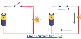
Like this picture, you have a open and closed circuit 1747320698448.png
Its the same for the endstop.
 
We're more focused on actual Voron machines here. for mystery-meat-started-as-cr10, you may find more useful help over at the klipper discourse. https://klipper.discourse.group/

still:for sensorless homing: you should definitely be seeing the endstops as "open" before you start homing. I'm curious if PC0 is actually the right pin: that's the endstop for motor4, which seems like an odd place for an x motor to be connected... I'd probably start by verifying the pin, and making sure the diag jumper for that motor is installed.

 
I find it a little strange that you bought a modified 3Dprinter but never printed but the fact that you are willing to get it working is admirable.

So triggered endstop. What happens when you manually trigger it and query the endstop? I am recalling from memorry since I don't use physical endstops. the ! will reverse the PIN so if you have endsto_pin: PC0 and its triggered, !PC0 will make it not triggered.

Like this picture, you have a open and closed circuit View attachment 5936
Its the same for the endstop.

Well, I was only expecting the modifications to be that it ran Klipper. That was the whole description for the printer advert "Now runs Klipper", that was it.
I googled what IKlipper was and thought "huh, that would actually be useful". It was only after I started trying to set things up I realised what I was looking at for nearly every part except the frame and motors wasn't what would be on a stock CR10.

Like I said in my post, I think the owner had some mental health issues.

Anyway, I queried the endstop when I was manually pressing, then queried on releasing the physical endstop. It changed nothing. It was not registering the state change of the switch.

I tried the configurations of:
endstop_pin: PC0
endstop_pin: !PC0
endstop_pin: ^PC0
endstop_pin: ^!PC0

While the default state did change, it still did not register the change in state when the switch was pressed.

i.e; If the default state was open, after pressing the switch the state was still open. If the default state was triggered, after pressing the switch the state was still triggered.

I appreciate the help so far.

We're more focused on actual Voron machines here. for mystery-meat-started-as-cr10, you may find more useful help over at the klipper discourse. https://klipper.discourse.group/

still:for sensorless homing: you should definitely be seeing the endstops as "open" before you start homing. I'm curious if PC0 is actually the right pin: that's the endstop for motor4, which seems like an odd place for an x motor to be connected... I'd probably start by verifying the pin, and making sure the diag jumper for that motor is installed.


I'm a bit old for discord, but I will look into it, thanks.

I did download the manuals for all the boards, but I will double check the pin. I'll double check and reply with the findings, plus my printer.cfg. The clue may be in there.

Again, I appreciate the help so far.
 
The voron discord has up to and including retired folks on it, and is rwally the main platform for voron help. I honestly don't think it is age-limited at all. but, more importantly, the klipper *discourse* is a forum, not unlike this one.

That all aside, I think a copy of the config, and a photo of how the manta is wired would both be very useful things.
 
Agreed with shiftingtech, lets see the printer.cfg and a photo.

Also, I am a grandfather or two and I use Discord daily for many things I do.
 
Yeah, we "olds" get to use Discord too. :p Sometimes the Voron one can feel like trying to drink from a firehose, but it is loaded with knowledgeable, helpful people.
 
The voron discord has up to and including retired folks on it, and is rwally the main platform for voron help. I honestly don't think it is age-limited at all. but, more importantly, the klipper *discourse* is a forum, not unlike this one.

That all aside, I think a copy of the config, and a photo of how the manta is wired would both be very useful things.
Agreed with shiftingtech, lets see the printer.cfg and a photo.

Also, I am a grandfather or two and I use Discord daily for many things I do.
Yeah, we "olds" get to use Discord too. :p Sometimes the Voron one can feel like trying to drink from a firehose, but it is loaded with knowledgeable, helpful people.
Again, thanks for the responses.

I'll look into Discord. I have resisted so far, but I'll give it a go.

This is my current printer.cfg


INI:
# Manta M8P + CB1 + EBB SB2209 (CAN)

[include mainsail.cfg]

[mcu]
canbus_uuid: e48efe7da441
canbus_interface: can0

[mcu EBBCan]
canbus_uuid: a420eb1fbf59

[virtual_sdcard]
path: /home/biqu/printer_data/gcodes

[printer]
kinematics: cartesian
max_velocity: 300
max_accel: 3000
max_z_velocity: 15
max_z_accel: 350
square_corner_velocity: 5.0

[temperature_sensor MCU]
sensor_type: temperature_mcu

[temperature_sensor SoC]
sensor_type: temperature_host

###################################
# X Stepper
###################################

[stepper_x]
step_pin: PE2
dir_pin: !PB4
microsteps: 16
rotation_distance: 40
position_min: 0
position_endstop: 0
position_max: 500
homing_speed: 50
homing_retract_dist: 5
homing_positive_dir: false
endstop_pin: tmc2209_stepper_x:virtual_endstop  # (keep it like this!)

[tmc2209 stepper_x]
uart_pin: PC10
interpolate: True
run_current: 1.0
hold_current: 0.7
sense_resistor: 0.110
stealthchop_threshold: 0
diag_pin: PC11
driver_SGTHRS: 250


###################################
# Y Stepper
###################################

[stepper_y]
step_pin: PF12
dir_pin: PF11
microsteps: 16
rotation_distance: 40
endstop_pin: ^PC0
position_min: 0
position_endstop: 0
position_max: 500
homing_speed: 50
homing_retract_dist: 5
homing_positive_dir: false


[tmc2209 stepper_y]
uart_pin: PF13
interpolate: True
run_current: 0.8
hold_current: 0.7
sense_resistor: 0.110
stealthchop_threshold: 0
##diag_pin: PB3
driver_SGTHRS: 255

###################################
# Z Stepper
###################################

[stepper_z]
step_pin: PD7
dir_pin: PD6
enable_pin: !PF10
microsteps: 16
rotation_distance: 40
gear_ratio: 80:16
position_min: -5
position_max: 500
homing_speed: 8
second_homing_speed: 3
homing_retract_dist: 3
endstop_pin: probe:z_virtual_endstop

[tmc2209 stepper_z]
uart_pin: PF9
interpolate: true
run_current: 0.8
hold_current: 0.8
sense_resistor: 0.110
stealthchop_threshold: 0

###################################
# Z1, Z2, Z3 Steppers
###################################

[stepper_z1]
step_pin: PD3
dir_pin: !PD2
enable_pin: !PD5
rotation_distance: 40
gear_ratio: 80:16
microsteps: 16

[tmc2209 stepper_z1]
uart_pin: PD4
interpolate: true
run_current: 0.8
hold_current: 0.8
sense_resistor: 0.110
stealthchop_threshold: 0

[stepper_z2]
step_pin: PC9
dir_pin: PC8
enable_pin: !PD1
rotation_distance: 40
gear_ratio: 80:16
microsteps: 16

[tmc2209 stepper_z2]
uart_pin: PD0
interpolate: true
run_current: 0.8
hold_current: 0.8
sense_resistor: 0.110
stealthchop_threshold: 0

[stepper_z3]
step_pin: PA10
dir_pin: !PD15
enable_pin: !PA15
rotation_distance: 40
gear_ratio: 80:16
microsteps: 16

[tmc2209 stepper_z3]
uart_pin: PF8
interpolate: true
run_current: 0.8
hold_current: 0.8
sense_resistor: 0.110
stealthchop_threshold: 0

###################################
# Extruder (EBB SB2209)
###################################

[extruder]
step_pin: EBBCan:gpio6
dir_pin: EBBCan:gpio7
enable_pin: !EBBCan:gpio8
microsteps: 16
rotation_distance: 22.6789511
gear_ratio: 50:17
nozzle_diameter: 0.400
filament_diameter: 1.75
heater_pin: EBBCan:gpio0
sensor_type: EPCOS 100K B57560G104F
sensor_pin: EBBCan:gpio27
min_temp: 10
max_temp: 270
min_extrude_temp: 170
control: pid
pid_kp: 26.213
pid_ki: 1.304
pid_kd: 131.721

###################################
# Bed Heater
###################################

[heater_bed]
heater_pin: PB7
sensor_type: Generic 3950
sensor_pin: PA0
control: watermark
min_temp: 0
max_temp: 130

###################################
# Probe (Voron Tap)
###################################

[probe]
pin: EBBCan:gpio2
x_offset: 0
y_offset: 0
z_offset: 0
samples: 3
samples_result: median
samples_tolerance: 0.006
samples_tolerance_retries: 3
speed: 5.0

[filament_switch_sensor runout_sensor]
pause_on_runout: true
runout_gcode: PAUSE
switch_pin: EBBCan:gpio10


###################################
# End of file
###################################

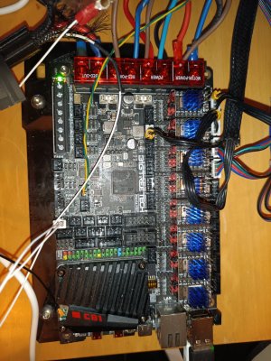
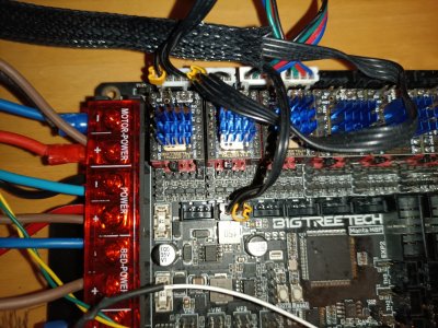
Images of the m8p wiring:

IMG_20250518_195347_856 (Large).jpg

IMG_20250518_195401_066 (Large).jpg

Again, thanks for any help.
 
Its not discord, it is discourse!
I am 60 and I am on this forum and discourse also, but discord I find a painfull mess and @shiftingtech said discourse!

Please be sure to read their guidelines of how to ask for help. You should have all the info they need and as long as you follow their setup they are very efficient at helping you out. Most klipper dev’s are there too and they have a wealth of knowledge.

I should say congrats on your progress sofar. You seem to have skipped my first 4 years of dabbling with 3d printers and jumped in somewhere at the end of my journey to date.
It can be daunting but it is immensly rewarding, don’t give up, between this forum and the klipper discourse you will find your answers I am sure.
 
That photo you've got there concerns me a little: the (I assume) endstop appears to be a 2 pin connector jammed into a 3 pin port. so that's problematic to begin with (is it even making proper contact?), but also, assuming it is indeed working out electrically, it also appears to be PF4, not PC0, based on

And those pins do not look like they line up, the are probably sliding down the side of the real holes. I would change that plug either for two single dupont plugs or a proper three pin that matches. I know from experience this seems attractive as a quick fix but down the road it will give you heartburn. Ask me how I know?
 
Its not discord, it is discourse!
I am 60 and I am on this forum and discourse also, but discord I find a painfull mess and @shiftingtech said discourse!

Please be sure to read their guidelines of how to ask for help. You should have all the info they need and as long as you follow their setup they are very efficient at helping you out. Most klipper dev’s are there too and they have a wealth of knowledge.

I should say congrats on your progress sofar. You seem to have skipped my first 4 years of dabbling with 3d printers and jumped in somewhere at the end of my journey to date.
It can be daunting but it is immensly rewarding, don’t give up, between this forum and the klipper discourse you will find your answers I am sure.

Ahhh. Sorry, I just thought Discourse was something within Discord. I'll try to.look onto it today after work.

As for the congratulations, you may want to hold off the party balloons, it's not working yet. 😆

I don't know if skipping 4 years of knowledge and experience, is a good or a bad thing yet. 😁

Thank you!
That photo you've got there concerns me a little: the (I assume) endstop appears to be a 2 pin connector jammed into a 3 pin port. so that's problematic to begin with (is it even making proper contact?), but also, assuming it is indeed working out electrically, it also appears to be PF4, not PC0, based on
And those pins do not look like they line up, the are probably sliding down the side of the real holes. I would change that plug either for two single dupont plugs or a proper three pin that matches. I know from experience this seems attractive as a quick fix but down the road it will give you heartburn. Ask me how I know?

Thanks for the responses.

Ok, makes sense,although it does beg the question why the original user would use a 2 pin plug. It sounds like they did a lot of lazy shortcuts.

Would I be better replacing the Endstop plug, or just sacking it completely and changing it to virtual?
 
Last edited:
Ahhh. Sorry, I just thought Discourse was something within Discord. I'll try to.look onto it today after work.

As for the congratulations, you may want to hold off the party balloons, it's not working yet. 😆

I don't know if skipping 4 years of knowledge and experience, is a good or a bad thing yet. 😁

Thank you!


Thanks for the responses.

Ok, makes sense,although it does beg the question why the original user would use a 2 pin plug. It sounds like they did a lot of lazy shortcuts.

Would I be better replacing the Endstop plug, or just sacking it completely and changing it to virtual?
In my opinion it is best to try and get it to work as close as the original person intended. After that you can change things and you have some starting point you are certain of it works. So get the installed end limit switches working before going to switchless homing. Yes many people make shortcuts for whatever reason it might seem the right thing to do at the time. My machine was also full of those and thus my signature.

When you get this to work you jumped straight into the "expert" category, and yes I am sure you will manage with the help at hand here and on the discourse.
 
If it were me, I'd depin it and put those in a proper 3-pin connector. It's not that hard and a good skill to have (you'll need it).
 
In my opinion it is best to try and get it to work as close as the original person intended. After that you can change things and you have some starting point you are certain of it works. So get the installed end limit switches working before going to switchless homing. Yes many people make shortcuts for whatever reason it might seem the right thing to do at the time. My machine was also full of those and thus my signature.

When you get this to work you jumped straight into the "expert" category, and yes I am sure you will manage with the help at hand here and on the discourse.
If it were me, I'd depin it and put those in a proper 3-pin connector. It's not that hard and a good skill to have (you'll need it).

Sounds like a plan. I've ordered a crimping tool that includes Dupont and jst xh connectors. I'll do it properly.

Although I will say, the switch must be making a circuit as the blue LED on it lights up when the switch is switched.
 
Sounds like a plan. I've ordered a crimping tool that includes Dupont and jst xh connectors. I'll do it properly.

Although I will say, the switch must be making a circuit as the blue LED on it lights up when the switch is switched.
It could get the common and V from those pins at the moment but as @shiftingtech mentioned it looks like the wrong pin. Also if this connection is questionable with the wrong plug fitting somewhat loosely in that recepticle, its anybodies guess how long it will withstand heatcycles and vibration.
 
You
Sounds like a plan. I've ordered a crimping tool that includes Dupont and jst xh connectors. I'll do it properly.

Although I will say, the switch must be making a circuit as the blue LED on it lights up when the switch is switched.
I don't think you'll necessarily need the crimping tool (though it's definitely a good thing to have). should be able to just transfer the existing pins to the correct shell.
 
You

I don't think you'll necessarily need the crimping tool (though it's definitely a good thing to have). should be able to just transfer the existing pins to the correct shell.
I was going to say the same thing. Just pop the pins out of the 2-position shell and put them in a 3-position shell. Done.
 
It could get the common and V from those pins at the moment but as @shiftingtech mentioned it looks like the wrong pin. Also if this connection is questionable with the wrong plug fitting somewhat loosely in that recepticle, its anybodies guess how long it will withstand heatcycles and vibration.
You

I don't think you'll necessarily need the crimping tool (though it's definitely a good thing to have). should be able to just transfer the existing pins to the correct shell.
I was going to say the same thing. Just pop the pins out of the 2-position shell and put them in a 3-position shell. Done.
Thanks for the responses. I didn't realise the pins would pop out, so will give that a go. Some of the connections, although working, could do with being recrimped and remade, so the crimper wont go to waste.

I haven't had a chance to redo the jst on the y, but I did change the printer.cfg to match the proper pins, and now it registers as open/triggered, so the switch seems to be working fine. But progress is still stalled a bit. I still can't "home" because x, z and probe are still saying triggered.

I double checked my x settings vs the generic + TMC2209 config from BTT. The endstop still registers as Triggered, but now the x motor actually moves, a little.

This is my current configuration for x:
Code:
[stepper_x]
step_pin: PE2
dir_pin: !PB4
enable_pin: !PC11
microsteps: 16
rotation_distance: 40
position_min: 0
position_max: 500
position_endstop: 0
endstop_pin: tmc2209_stepper_x:virtual_endstop

[tmc2209 stepper_x]
uart_pin: PC10
diag_pin: PF3
run_current: 1.2
hold_current: 0.7
sense_resistor: 0.110
stealthchop_threshold: 0
driver_SGTHRS: 70

When I press home I get 2 seconds of tool head juddering along x (maybe moving 3mm), and receive the following error:
G28
Endstop stepper_x still triggered after retract.

So I tried DUMP_TMC STEPPER=stepper_x, to see what it came up with:

Code:
23:15// SG_RESULT:  00000018 sg_result=24
23:15// PWM_AUTO:   001700ff pwm_ofs_auto=255 pwm_grad_auto=23
23:15// PWM_SCALE:  000d0074 pwm_scale_sum=116 pwm_scale_auto=13
23:15// PWMCONF:    c80d0e24 pwm_ofs=36 pwm_grad=14 pwm_freq=1 pwm_autoscale=1 pwm_autograd=1 pwm_reg=8 pwm_lim=12
23:15// DRV_STATUS: 800c00c0 ola=1(OpenLoad_A!) olb=1(OpenLoad_B!) cs_actual=12 stst=1
23:15// CHOPCONF:   34010053 toff=3 hstrt=5 tbl=2 mres=4(16usteps) intpol=1 dedge=1
23:15// MSCURACT:   011001c3 cur_a=-61 cur_b=-240
23:15// MSCNT:      00000228 mscnt=552
23:15// TSTEP:      000fffff tstep=1048575
23:15// FACTORY_CONF: 0000000e fclktrim=14
23:15// IOIN:       21000041 enn=1 pdn_uart=1 version=0x21
23:15// OTP_READ:   0000000e otp_fclktrim=14
23:15// IFCNT:      00000010 ifcnt=16
23:15// GSTAT:      00000000
23:15// GCONF:      000001c0 pdn_disable=1 mstep_reg_select=1 multistep_filt=1
23:15// ========== Queried registers ==========
23:15// SGTHRS:     000000c8 sgthrs=200
23:15// TPOWERDOWN: 00000014 tpowerdown=20
23:15// COOLCONF:   00000000
23:15// TCOOLTHRS:  00000000
23:15// TPWMTHRS:   000fffff tpwmthrs=1048575
23:15// IHOLD_IRUN: 0008150c ihold=12 irun=21 iholddelay=8
23:15// SLAVECONF:  00000200 senddelay=2
23:15// ========== Write-only registers ==========
23:15DUMP_TMC STEPPER=stepper_x

In case there was a resistance problem with the toolhead/belt/etc, I plugged it into a 5th motor that the previous user had seemingly just attached to the back of the gantry, that has a plastic battarang glued to the end of the motor spindle (Why?) It seems to be spare as there was no wire for it. So, yeah, I plugged the x cable into it and ran the home test. It rotates about 33 degrees, before coming up this error:


Code:
23:20// SG_RESULT:  00000028 sg_result=40
23:20// PWM_AUTO:   001a0024 pwm_ofs_auto=36 pwm_grad_auto=26
23:20// PWM_SCALE:  0031003f pwm_scale_sum=63 pwm_scale_auto=49
23:20// PWMCONF:    c80d0e24 pwm_ofs=36 pwm_grad=14 pwm_freq=1 pwm_autoscale=1 pwm_autograd=1 pwm_reg=8 pwm_lim=12
23:20// DRV_STATUS: 800c00c0 ola=1(OpenLoad_A!) olb=1(OpenLoad_B!) cs_actual=12 stst=1
23:20// CHOPCONF:   34010053 toff=3 hstrt=5 tbl=2 mres=4(16usteps) intpol=1 dedge=1
23:20// MSCURACT:   00ef003c cur_a=60 cur_b=
23923:20// MSCNT:      00000028 mscnt=40
23:20// TSTEP:      000fffff tstep=1048575
23:20// FACTORY_CONF: 0000000e fclktrim=14
23:20// IOIN:       21000041 enn=1 pdn_uart=1 version=0x21
23:20// OTP_READ:   0000000e otp_fclktrim=14
23:20// IFCNT:      00000063 ifcnt=99
23:20// GSTAT:      00000000
23:20// GCONF:      000001c0 pdn_disable=1 mstep_reg_select=1 multistep_filt=1
23:20// ========== Queried registers ==========
23:20// SGTHRS:     0000008c sgthrs=140
23:20// TPOWERDOWN: 00000014 tpowerdown=20
23:20// COOLCONF:   00000000
23:20// TCOOLTHRS:  00000000
23:20// TPWMTHRS:   000fffff tpwmthrs=1048575
23:20// IHOLD_IRUN: 0008150c ihold=12 irun=21 iholddelay=8
23:20// SLAVECONF:  00000200 senddelay=2
23:20// ========== Write-only registers ==========
23:20DUMP_TMC STEPPER=stepper_x

I wasnt sure what that meant, so I had to ask ChatGPT to parse it a bit. It said:
ola=1, olb=1 - Open Load A and Open Load B are both still showing 1, meaning:
- The driver still detects no valid coil connection
- Even with another motor using the same cable

So looking at what others have written about this with the Manta m8P, the motor wiring may be wrong.

Not sure how acurate that is, but I'm going to have a look at the wiring tonight and see.

The M8P 1.1 pinouts for the motors are 2B 2A 1A 1B, but my motors dont seem to have any markings on to ID the pins, but as I understand it they look like the ones supplied by Creality for the CR10 so I will see if I can find a pinout for them. Although I have no clue what the 5th one is/was for.

This stuff feels so heavy for a noob, I just wanted to print something :cry:

Again, thanks for all the help.
 
Last edited:
Top