What's new
VORON Design

Register a free account today to become a member! Once signed in, you'll be able to participate on this site by adding your own topics and posts, as well as connect with other members!

Relay heater safety

120decibell

Administrator
Staff member
Moderator
Voron Owner
There is an underlying problem to one of the safety features of the Klipper thermal shutdown - most mosfets and SSR's have a tendency to fail closed (current is being passed). That means that if an SSR fails, even if Klipper shuts down, there is still 100% power going to the heated bed. I have assembled what I think is a solution to the issue that uses a mechanical relay as a safety measure.

Couple of caveats / design choices:
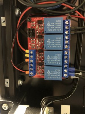
  1. I wanted to ensure that even if Klipper went into shutdown all cooling fans would keep running. This means keeping power to the MCU(s).
  2. This does not work with MCU-based toolhead boards like HUVUD, EBB36, etc since the heater control is at the toolhead.
  3. This is run entirely with Klipper. It can also be controlled with Moonraker.
In short, a multi-channel 5V relay board is used. The signal inputs come directly from the Raspberry Pi on any available GPIO connection and ensure the inputs are set to active high (try not to use the same GPIO pns as the ADXL). One relay is placed between the AC power source and the SSR. One relay is placed between the hot end heater and the MCU (this can be either the 24V source or the 0V/V- connection). Both relay connections use the normally open (NO) so that when the relay is not energized the connection is broken.

IMG_8883.JPG

Configure the Pi as an MCU as described in the Klipper docs.

All that is needed in Klipper is this section of configuration:

Code:
[mcu host]
serial: /tmp/klipper_host_mcu

[output_pin hotend_heater_safe]
pin: host:gpio5
pwm: False
value: 1
shutdown_value: 0

[output_pin bed_heater_safe]
pin: host:gpio6
pwm: False
value: 1
shutdown_value: 0

When Klipper is in shutdown for any reason, the relays are turned off and the heaters cannot be powered regardless of the mosfets or SSR. But connection is maintained to the MCUs so restarting Klipper is easy.

I'll update this when I have some time to add pictures and more clarification.
 
Not meaning to rain on anyone’s parade, but why do you think a relay is more reliable than an SSR? I don’t disagree that a failed-on SSR can create a hazardous situation; but a failed-on relay is the same. Perhaps a thermal fuse attached to the bed would be a more reliable backup.
 
A mechanical relay used in a normally open state will fail open about 99.999999% of the time, even in the very low percentage that it does fail. To me that means the highest chance of something did go wrong with the relay would be for an open (safe) circuit. If you feel differently then don’t use the mod.

This is not intended to replace the thermal fuse but to provide an additional safety that is easily resettable.
 
Not meaning to rain on anyone’s parade, but why do you think a relay is more reliable than an SSR? I don’t disagree that a failed-on SSR can create a hazardous situation; but a failed-on relay is the same. Perhaps a thermal fuse attached to the bed would be a more reliable backup.
Also just because its a relay and an ssr in series: now two devices need to fail before you can have a heater runaway.
 
Shelly PRO 1PM is a DIN mounted relay with power consumption meter and WIFI+LAN connection. It is costly but fits this purpose perfectly plus it gets you extra features and can be controlled from anywhere, not just from the PI. If you are using home assistant it has native integration. It can also be controlled via GPIO in addition to network control. There is a 2 channel version too called Shelly PRO 2PM. I will consider using 2-channel one, but not for hotend and bed but bed and 24V PSU, leaving only PI alway on. I wouldn't have power consumption of anything non-heater related otherwise.
 
Last edited:
Shelly PRO 1PM is a DIN mounted relay with power consumption meter and WIFI+LAN connection. It is costly but fits this purpose perfectly plus it gets you extra features and can be controlled from anywhere, not just from the PI. If you are using home assistant it has native integration. It can also be controlled via GPIO in addition to network control. There is a 2 channel version too called Shelly PRO 2PM. I will consider using 2-channel one, but not for hotend and bed but bed and 24V PSU, leaving only PI alway on. I wouldn't have power consumption of anything non-heater related otherwise.
If you do eventually do that, make sure to document it and share. I've looked at the Shelly options, but don't have enough knowledge to do it without instructions. I'd probably end up releasing the magic smoke or trying to burn my house down.
 
A mechanical relay used in a normally open state will fail open about 99.999999% of the time, even in the very low percentage that it does fail. To me that means the highest chance of something did go wrong with the relay would be for an open (safe) circuit. If you feel differently then don’t use the mod.

This is not intended to replace the thermal fuse but to provide an additional safety that is easily resettable.
120decibell, in your original post you stated, "SSR fails, even if Klipper shuts down, there is still 100% power going to the heated bed". Does your system trigger prior to the thermal fuse? If yes, what signal is used to trigger your system?

Maybe I am not understanding something, but other than being "easily resttable", what advantage is there over a thermal fuse? If the SSR fails and blows the thermal fuse, I will need to disassemble the machine to replace parts. I can't (as far as I know) reset a failed SSR or thermal fuse.
 
The way I put this together, Klipper has to intentionally hold the relays closed by applying signal voltage. If anything happens to Klipper or the Pi, the relays open and all heaters are disconnected. If Klipper has a heater error from lack of control or reaching max temperature Klipper will go into shutdown and will stop holding the relays closed, disconnecting the heaters. Theoretically the Klipper max temperature should be set to a level below the threshold of the thermal fuse as the thermal fuse should be the absolute failsafe.

If there is a true hardware failure then replacing hardware is unavoidable. However it is likely easier to replace just the SSR rather than both the SSR and the thermal fuse (especially if the thermal fuse is glued to the heater as some are).
 
I've got a handful of single relay modules that work simialrly to the ones you picture. I've had two stick open on me. One was used for 24v switching on an old ender 3, the other was in front of the PSU on my prusa. they're not the only ones in use, but that's two sets of failure protection that hasn't always worked.

However a safety cutout that might save the day is better odds of a safe failure than not having the failsafe.
Did you have a suppression diode installed?
 
I used allegedly optoisolted relay modules, the single channel version of the one pictured above i think. Should have all of the driver circuit onboard. Silkscren on the back shows a schematic diagram and maybe a diode across the coil. There's waht looks like a diode on the board but it's all tiny surface mount hard to read components.
 
The diode doesn't need to be big. It's called a flyback diode (among other names) and it serves to provide a path for the electric current that's created by the inductor when the circuit is opened because inductors does not react instantly to current changes due to the magnetic field that's stored on them. It's a safety measure.
 
I would respectfully disagree with the statement that a NO relay will fail open. In my experience, a mechanical NO relay, more times than not, will end up welding the contacts closed, and then there will be issues. Ironically, a relay failed in my clothes dryer just two weeks ago. One evening the dryer kept running even though the time was up. It is a NO relay but failed in the closed position.
 
Hi,

I have mounted couple of Shelly 1PM modules - similar to PRO, just different form factor. It is easy to use, you can also pre-set what condition the device should be in if there is power outage for example and costs less than the PRO version. The 1PM can accommodate DS18B20 sensor - that is to +125 celsius (257 F), but who knows if they are reliable at these temps. I am also new to 3D printing so not sure what the bed temperatures usually are. There is also power consumption "fuse", should it be higher then threshold, the device will turn off.
But I am running several of these around my house and I am super happy with them. You get remote control from your phone and you also get power consumptions stats.
 
I would respectfully disagree with the statement that a NO relay will fail open. In my experience, a mechanical NO relay, more times than not, will end up welding the contacts closed, and then there will be issues. Ironically, a relay failed in my clothes dryer just two weeks ago. One evening the dryer kept running even though the time was up. It is a NO relay but failed in the closed position.

The way a mechanical relay fails is from a high inrush current welding the contacts. The way an SSR fails is from ESD or inductive kicks. Each has a failure mode, but on the chance you manage to fail one closed, you're now back to as safe as you were with the stock wiring.
 
Failure mode is not categorical.
It depends on the environment, the properties of the relay, the load it is subjected to during its lifetime, and similar.

SSRs: I've mostly seen them fail shorted, measuring less than one ohm. But I've also seen them fail open.
Some due to no longer drawing any current on the control input. Perhaps due to a fried LED in the optocoupler, who knows...

Others in the form of a cold soldered (sloppy assembly) pcb mounted triac where one of the solder joints disconnected, or in one case didn't disconnect, but instead the solder joint made poor contact (high resistance) and got so hot the copper lifted from the pcb substrate.

Mechanical relays: I've seen several fail. Often shorted due to welded contacts.
But I've also seen failed relays with with melted solenoids. They tend to fail open, since they can no longer be activated.

And relays with enough soot or oxide buildup on the contacts to fail open. Happens a lot with some relays when the current never comes even close to the rated current, like after five years of only microamps through a busy relay rated for 2 amps. No idea why, just experience.

You can never be sure how a relay will fail, SSR or mechanical.
They often make, but sometimes they break.

One thing is sure though, with two or more relays in series the probablity of a short (heaters on) is greatly reduced.
Whether they are SSRs, mechanical, or mixed.
 
To add my 5 cents. As others have said a mechanical relay will fail closed because of large current at the moment of closing. The contacts will bounce creating an arc which welds them together. But I would presume that in this use case relay closes first and only after that the SSR closes. No current, no welding. This should reduce the chance of failure to minimum.
Moreover a chance of both relays failing at the same time is miniscule which makes the safety even better.

On the other hand, there is a possibility that the mechanical relay fails closed while the SSR is still working. This would go unnoticed in normal operation, creating false sense of safety. To mitigate this there would need to be additional sensing of the voltage on the output of the relay and a testing procedure (at startup maybe) to check that the relay is able to break the circuit. But now we are moving a little bit to the overengineered territory :)
 
I use a relays for years on my ender 3.
Wired to mains, so no main power to 24v PSU.
On my voron I used 2 relays, commanded by a single gpio pin from pi. One is turning off the mains to bed SSR and the other one the mains to the 24v PSU. I use mainsail to turn it on/off. I don't really care about the fans in a error state. A jammed fan can also do some damage.
In my opinion a bit of redundancy is always good.
 
Thanks for sharing this - I've been wanting to set up something like this for a while.

For SSRs, the most common failure mode is for them to fail short. From Omron:

Short-circuit failures represent the main failure mode and can result in an inability to shut OFF theload. Therefore, for fail-safe operation of control circuits that use SSRs, do not use circuits that shut OFF the load power supply only with an SSR, but rather also use circuits with a contactor or breaker that shuts off the load when the SSR fails.

Re: the risk of the relays failing short - these relay boards are pretty cheap, one option would be to replace them on a schedule. I think it would also be possible to write a script to test whether the relay works by turning off the relay and on the heater, and checking that the temp doesn't rise.
 
Top