What's new
VORON Design

Register a free account today to become a member! Once signed in, you'll be able to participate on this site by adding your own topics and posts, as well as connect with other members!

Question Trident Fixing uneven Bed

X11-35/2

Member
Printer Model
Trident 300mm
Extruder Type
Clockwork 2
Cooling Type
Stealthburner
Hi there,
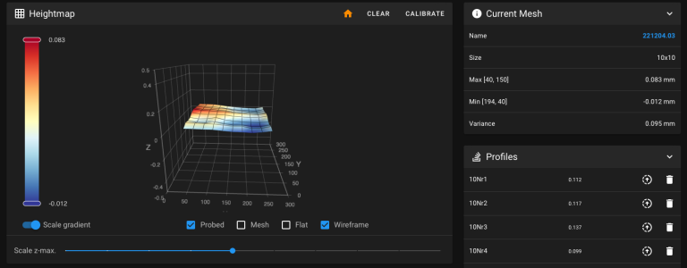
I've just finished my Trident Build& have done a few hours of printing now, about 45h, not even done with all the "cosmetics" like Skirts etc. So also no Cerials for me....
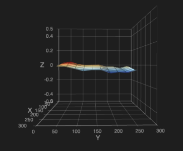
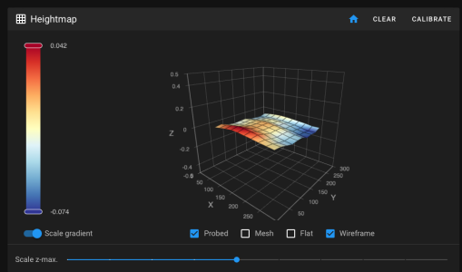
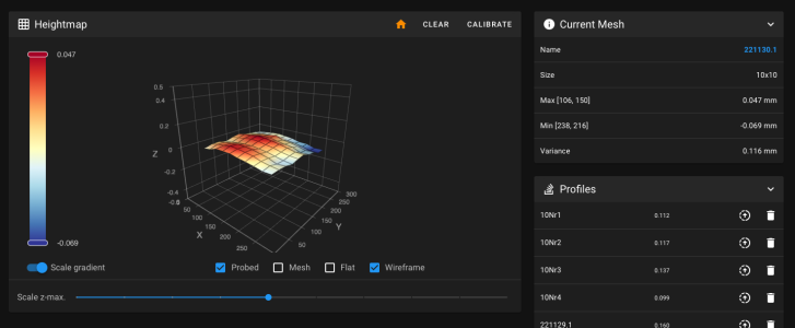
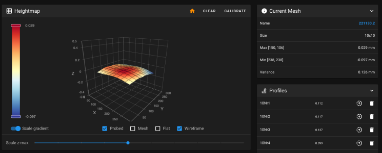
Sadly I'm relatively unhappy with the flatness of my mesh.
About my Setup:
Trident 300mm
Probe: Super Pinda aka P&F NBN 2,5-8GM35-E1-Y
Aluminum Bed: Flatness less than 0,2mm/m

I firstly used the trick from the discord to just fine tune Y extrusions and that surely helped, but there is still about 1/10 error around the surface. The Thing, that is the most important to me is the "Bow" on the X Plane.
Looks like problem on the extrusion or rail.
I rotated my Rail already 90° (so the side from the rail is now used for the cable chain and so on)
Sadly that didn't helped, I'm now thinking about flipping the Extrusion upside down, to look if the Bow just turns the other way round.

Whats your thaugts about?
Do you guys had similar issues?

Please don't start any "Mesh can compensate" posts.
I want to create a solid base model, so compensation has less to do.
Better base results in better Results, I think that's something we all should be fine with.

Sorry my bad English, but I prefer a Forum over some Discord Posts, cause I don't always have like 6h to read all messages before something "Disappears"

Regards
X11-35/2 aka Tjard

[gonna add mesh later, sadly forget to do a save config last time]
 
Last edited:
So here is a Mesh, Picture and raw data:


#*# [bed_mesh 221129.18]
#*# version = 1
#*# points =
#*# -0.005000, 0.008125, 0.020000, 0.028125, 0.026875, 0.019375, 0.013125, 0.003125, -0.003125, -0.010000
#*# 0.006250, 0.016875, 0.030625, 0.041875, 0.040000, 0.030000, 0.021250, 0.000000, -0.011875, -0.013750
#*# -0.018750, -0.011250, -0.001875, 0.011250, 0.014375, 0.005625, 0.003125, -0.017500, -0.032500, -0.033125
#*# -0.029375, -0.021250, -0.011875, 0.001875, 0.003125, -0.002500, -0.014375, -0.029375, -0.043125, -0.051250
#*# -0.023750, -0.020000, -0.008750, -0.000625, 0.004375, -0.003750, -0.011875, -0.025625, -0.038125, -0.043750
#*# -0.018750, -0.011875, -0.004375, 0.003750, 0.005625, -0.001250, -0.010625, -0.026250, -0.038750, -0.044375
#*# -0.039375, -0.030625, -0.018750, -0.014375, -0.018125, -0.027500, -0.039375, -0.048125, -0.063750, -0.074375
#*# -0.045000, -0.032500, -0.022500, -0.015625, -0.018125, -0.027500, -0.038125, -0.053125, -0.065000, -0.065625
#*# -0.051250, -0.042500, -0.033750, -0.033125, -0.035625, -0.043125, -0.048750, -0.060000, -0.072500, -0.070000
#*# -0.033750, -0.021875, -0.015625, -0.011875, -0.014375, -0.020000, -0.027500, -0.033750, -0.044375, -0.042500
#*# x_count = 10
#*# y_count = 10
#*# mesh_x_pps = 2
#*# mesh_y_pps = 2
#*# algo = bicubic
#*# tension = 0.2
#*# min_x = 40.0
#*# max_x = 259.96
#*# min_y = 40.0
#*# max_y = 259.96000000000004
 

Attachments

  • Bildschirmfoto 2022-11-29 um 17.19.21 PM.png
    Bildschirmfoto 2022-11-29 um 17.19.21 PM.png
    99.3 KB · Views: 71
I find it strange that rotating the extrusion the linear rail is attached to didn't change anything. To me, that points to an issue with the rail or bed. You could look into the rail backer mod to reduce the bowing due to the aluminum extrusion and steel linear rail heat expansion differences.

1. Does this show up in your prints?
2. How big is this bow? The map can be deceiving if you let the colors tell you how "bad" it is instead of focusing on the numbers.
3. What is your bed max power set to? Heating the bed too fast will cause it to warp slightly I believe the stock config limits bed heating power to .6


I do understand wanting to get the machine as flat as possible, but we have bed mesh for this exact reason. We can only hold tolerances to a certain level when building these machines, even less so when you add heat expansion into the mix, so we need a bed mesh to compensate.
 
1. yes, in inconsistent squish, leading to a uneven second layer which leaves strange gaps in the outer shell
2. what do you mean with how big? die middle to the corner is about 0.04. also strange is that the bed falls along the y plane even with z tilt about 0,04mm
3. 0.6 and I also calculated it with the 0,4W/cm^2 the value seems okay.

but the bowing on the x rail should be front/back with single mgn12 or am I wrong?
 

Attachments

  • Bildschirmfoto 2022-11-29 um 17.21.29 PM.png
    Bildschirmfoto 2022-11-29 um 17.21.29 PM.png
    30.1 KB · Views: 53
  • Bildschirmfoto 2022-11-29 um 17.19.21 PM.png
    Bildschirmfoto 2022-11-29 um 17.19.21 PM.png
    99.3 KB · Views: 37
I apologize for question 2, I had been writing my post throughout the morning before you added the mesh picture and raw data, so I never refreshed the page to see your update.

The bowing on the X rail should mostly be front and back, yes, but it still has an effect on up and down.

From what I've seen of other bed meshes, yours seems to be around the tolerances of others. Part of the problem with bed mesh is that unless you're probing a known flat surface (like the raw aluminum plate), every number you get is going to be skewed by your magnetic sheet and build plate.

If you haven't seen them already, this is some good reading about backers and their effects on bed mesh, and Andrew Ellis has a tuning guide that could help with the second layer issues as well.
 
It's not related to your question, but you can get a serial without skirts or panels. The only major requirement is wire management.
 
Do you have a known flat surface to probe and test? A sheet of glass perhaps?

Would be curious to see if the ripples in your mesh are from the magnetic sheet installation. When you installed it, do you recall if you paused once in the middle to peel off more paper backing?
 
@120decibell okay thank you.

@Le0n I'm using an inductive probe, so the glass wouldn't trigger it, but I did further investigations on cold printer with normal setup (mesh 221130.1) on cold printer with normal bed, magnet, springsteel, magnet, bed I have laying around (mesh 221130.2)
looks like the y waves are from the print surface (swapping Springsteen& pei didn't changed so maybe be a problem of the magnet)
and the x bow is related to the gantry
 

Attachments

  • Bildschirmfoto 2022-11-30 um 07.15.01 AM.png
    Bildschirmfoto 2022-11-30 um 07.15.01 AM.png
    133.1 KB · Views: 31
  • Bildschirmfoto 2022-11-30 um 07.14.53 AM.png
    Bildschirmfoto 2022-11-30 um 07.14.53 AM.png
    130.4 KB · Views: 46
Do you have all the bed mounting bolts tightened down? I recall seeing a suggestion to leave the front two just slightly loose to allow for movement from temperature change.
 
I was able to find out something more about the error.
First I got a Misumi X Extrusion, which didn't do the trick, but than I tried flipping the Linear rail. here is the Result.
Still not perf but a bit better.
 

Attachments

  • Bildschirmfoto 2022-12-04 um 14.17.48 PM.png
    Bildschirmfoto 2022-12-04 um 14.17.48 PM.png
    120.7 KB · Views: 54
That's plenty close enough IMHO. I often get about that variance and I get perfect first layers. Mind, I'm also using Klicky, auto-z and just implemented KAMP adaptive mesh (replaced a different adaptive mesh).
 
Don't disagree with anything I see. But those look suspiciously like "lanes" I would double check and make sure the rails are tight and have enough connection points.
 
My bed on a calibrated surface plate (AA) is only a bit better. Between the magnetic surface and the machining it doesn't look bad to me.
 
Top