What's new
VORON Design

Register a free account today to become a member! Once signed in, you'll be able to participate on this site by adding your own topics and posts, as well as connect with other members!

A/B vs X/Y

tetra

Member
Greetings Voronians,
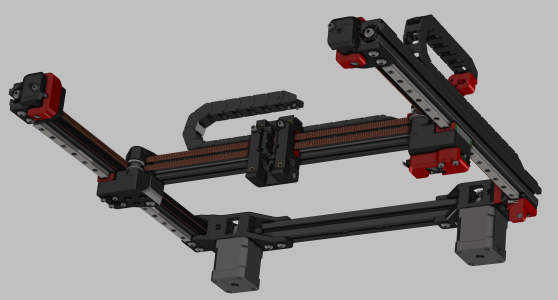
I'm in investigation mode, and have not built a Voron yet. I'm examining the (really fantastic) Trident CAD model, as I prefer the bed to move in Z vs the XY gantry system. If/when I build a Voron, it will most likely be the Trident. I'm curious about the design decision to use an A/B belting configuration for the gantries. IIUC, both motors have to be operational even for straight X or Y moves. From digging into the model, teeth on the back of the extruder mount lock both of the belts to the mount. It seems like if I only moved one motor, the nozzle would actually trace a diagonal. There must be an advantage to this type of configuration, but I am drawing a blank. I have a CoreXY Stacker S4, and it uses one stepper for X and another for Y in a manner that is pretty straightforward. Why the belt/stepper configuration on the Trident, and what about it is better?
I'm not trying to say the Stacker method is better, nor am I trying to start a war on the topic, I am genuinely ignorant about why this design won out. Looking at the model, it's very obvious you know what you're doing and I know there's a reason.

Thanks for helping me understand this design.
voron-gantry-system-sm.png
 
Last edited:
Trident uses the CoreXY kinematics in klipper. It involves having stationary motors that each move the toolhead in a diagonal direction. Then the kinematics can calculate the speed and direction to turn each motor for straight lines or curved lines in any direction. The Stacker you mention appears to use a motor/s for the Y axis and a motor/s for the X axis which is not CoreXY kinematics but instead Cartesian kinematics. CoreXY kinematics are typically able to move and accelerate faster due to not having the weight of a motor on the X axis.

The A/B you mention is just the naming scheme for the belts primarily. In klipper they are still stepper_x/y.
 
Aha! So the Stacker is not a CoreXY - learn something everyday. So this method is far superior to a Cartesian system like the Stacker. Cool, thanks for your message.
 
Keep in mind that CoreXY does have its limitations, the major one being the fact that it doesn't scale very well: it becomes incredibly difficult to properly tension the belts over this size. Some other 3D printer designs like RatRig's V-Core solve that by using 9mm width belts instead of 6mm, as this alone increase the rigidity of the belt and allows an increase on the print volume.
 
Interesting. I went and looked at RatRig's site - cool intro on the landing page. So the issue is belt stretch I assume? Any thoughts of using something like perforated steel banding and pulley/sprocket hybrid wheels for the motion system rather than toothed belts and pulleys? I recently got some stainless steel zip ties and they are super thin, super flexible, and super strong. It would be very difficult to stretch these under the forces I expect occur on the printer. Using that material, and maybe a bit wider, that has been punched in a line of appropriately shaped holes down its centerline at a pitch to to coincide with a pully/sprocket sandwich at the steppers might be a way to scale the X/Y drive system's size larger and still maintain accuracy. (totally spit-balling on that obviously ;)) And, definitely not an off-the-shelf item, but it seems like it would work. I wonder if anything like that already exists?
 
Interesting. I went and looked at RatRig's site - cool intro on the landing page. So the issue is belt stretch I assume? Any thoughts of using something like perforated steel banding and pulley/sprocket hybrid wheels for the motion system rather than toothed belts and pulleys? I recently got some stainless steel zip ties and they are super thin, super flexible, and super strong. It would be very difficult to stretch these under the forces I expect occur on the printer. Using that material, and maybe a bit wider, that has been punched in a line of appropriately shaped holes down its centerline at a pitch to to coincide with a pully/sprocket sandwich at the steppers might be a way to scale the X/Y drive system's size larger and still maintain accuracy. (totally spit-balling on that obviously ;)) And, definitely not an off-the-shelf item, but it seems like it would work. I wonder if anything like that already exists?
Not stretching, tensioning properly. Over 350mm at X and Y the belt length becomes so long that tensioning the belt at a proper level is dangerous for the stepper motors shafts. There are double shear designs that can help prevent this sort of damage, but the cost starts to pile up.
 
Makes sense. I just pinged them for data on that, as I could not readily find this on their site. When I hear back, I'll post what they say. Gauge is likely the primary determining factor, and even a very thin hardened stainless belt would still have a pretty high tensile strength in comparison with the timing belts used now. It will indeed be very interesting what the limitations are. Stay Tuned! ;)
 
@shiftingtech here's what Dymco said
Thank you for your contact.
These are guidelines of pulley diameter.
Open end belt ⇒belt thickness x 400
Endless belt without any holes⇒belt thickness x 700
Perforated endless belt ⇒belt thickness x 800
These coefficients are different from plastic and rubber belts.
Metal is rigid and cannot bend around a small pulley.

In case of sprocket pulley, we recommend pulley diameter as large as possible.
Belt holes are driven by pins. This fact itself damages the belt.
So, bending stress should be minimum.
Hope you can employ bigger diameter.
So yes, it will absolutely need larger size pulleys exactly as you note. I don't see that as an absolute death knell to using this type of belt / pulley / sprocket configuration in 3D printers per se, but certainly not in the current design paradigm that are timing-belt based, and pulley sizes are sized accordingly. Given the restrictions and recommended guidelines they sent, at the thinnest belt material offered (0.1mm) the minimum pulley size would be ~50-80mm (depending on open vs. endless type), with sprocket size as large as can be tolerated. I have no idea if that belt thickness would be adequate for the task, so it could end up being a much larger pulley & sprocket minimum than that. Obviously that would require a complete re-think of the design of the printer. Everything is a tradeoff.

I guess other mitigating options while still using timing belts would involve supporting the stepper shaft on both sides of the pulley to reduce load on the motor itself, or have the pulley on essentially a jackshaft with a 1-1 gear to the stepper - so no direct tension load on the stepper shaft itself, and/or possibly bumping up the XY steppers to the next bigger NEMA frame size. Of those, moving to a jackshaft methodology may be a cost-effective way to go. I'd be interested in your thoughts on that.

Thanks again for helping to increase up my understanding of all this, I do appreciate that a lot.

Cheers
 
I think my concern with that large a drive pulley (regardless of direct drive vs jackshaft) is that it's really going to change the speed/power balance. You won't have much power (so likely low accelerations), and it might even be to the point that stepper resolution becomes an issue
 
I think I may have been unclear in that last post. My understanding of the issue was that tensioning the standard timing belts imposed a high stress on the motor shaft. In my last post I talked about the metal belts as a possibly remedy, but acknowledged it would require a major redesign to accommodate - whatever that might entail. And your analysis of the diameter and it's effect on acceleration was enlightening for me. Some of that might be absorbable through gearing, and running the motor faster, but stepper power falloff at speed would probably creep in eventually.

In the second paragraph, I moved back to the original design of the Voron, and I offered some options that could probably help while still using the current timing belt scheme, one of which was the jackshaft idea. This would allow keeping the same size pulleys, while increasing the pulley shaft diameters and beefing up the bearings, and for the drive pulley, employing a 1:1 geared connection to the stepper which would then be under no tensional loading. It would require changing the sign on direction, but otherwise would behave exactly as it does now. It seems like this could be a minimal change to the stepper mounting printed part to accommodate at a minimum, and all pulley mountings as worst case to accommodate larger shafts and bearings everywhere.
 
Apologies, I don't think you were particularly unclear, i just read too fast. There are a number of designs currently doing the dual support thing (take a look at monolith gantry, just as an example). That's pretty well established as necessary if you want to increase the belt tension.

Jackshafts seem to be less in favor at the moment. Current thinking seems to be that they don't offer much benefit, while having potential baggage in terms of possible precision loss & backlash issues.
 
Top