What's new
VORON Design

Register a free account today to become a member! Once signed in, you'll be able to participate on this site by adding your own topics and posts, as well as connect with other members!

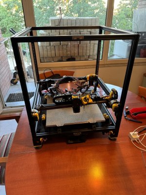
a secondhand Voron 2.4 350 being rebuild after it traveled nearly 2000 km by air, in a suitcase!

3dCase

Well-known member
So the journey is done and the rebuilding has started.
The plan is to build it up as it came apart, then troubleshoot. The reason is that I never worked with this printer before, and my dad only very little. I do not know the original builder, so no knowledge of how well this person did the work.
I will simply stick it together and let it find its own squareness and see what we have.
Also this is my first klipper machine so that part will be challenging also.
First day of the build was the unpacking and evaluating if there had been any bumps or knocks. All seems fine so I can start.
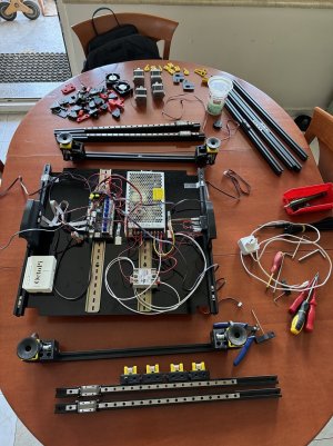
6voron.jpg
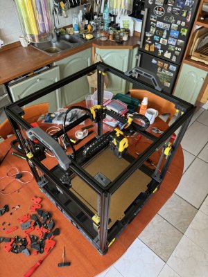
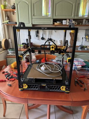
I placed the parts on the kitchen table, because my work table is full with other unfinished projects such as my own design printer, A 3d printed working Harley Davidson model I drew up in cad, and several other half forgotten things.
This way you can sort your parts and any amount of hardware quickly shows you where they are supposed to go. I used to rebuild printing machines in the field for years and always as the machine was placed out in parts over several pallets on the work floor, the owner came by to ask if I would manage to get that all back together again. The answer till now was always a resounding yes, so I am not going to change that any day soon.
Next I stuck the base together, obviously first go with the right member on the left, just as a test ;)
Once that was out of the way it all slipped in nicely.
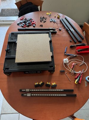
5voron.jpg
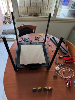
At this point I am already thinking ahead and trying to spot my next mistake. So far so good I think and I proceed with the uprights.
4voron.jpg
I have not yet fixed the z motor brackets yet, as I am not yet sure if it will be possible to thread the belts through with the motor tight. I think it will but I am expecting it to be easier this way.
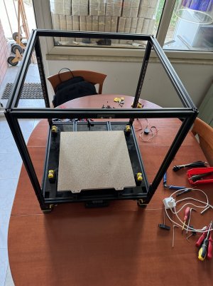
Now I fit the top members.
3voron.jpg
I forgot to register exactly where those tensioners went so I had to think that through a bit harder, I think I know where they should go so the top members are in the right place and in the correct orientation.
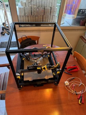
Now we slip in the gantry
2voron.jpg
voron9.jpg
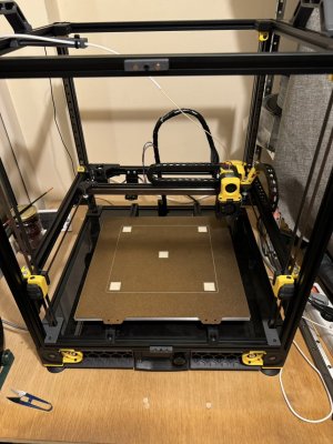
And instantly it looks more like a Voron already.
Now I fitted the carriage block screws to all four corners so the whole gantry can move up and down as it should.
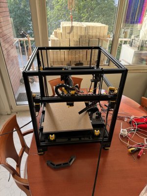
I have to tie up the gantry and suspend it so I can pre-adjust a rough level.
voron8.jpg
By adjusting those tie-wraps the gantry can be set to a reasonably accurate horizontal.
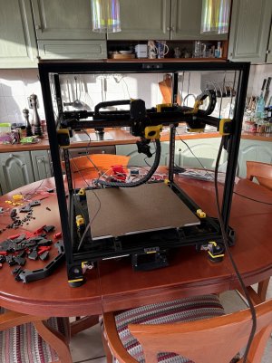
voron7.jpg

And that is where I am at right now. I will clean up that wiring a little and install some stretchy cable protecting sleeves in those cable chains. At the same time I will also thread the two rear z motor cables back in the cable chain. My dad had a problem and my brother found there were broken cables there so the two rear cables have been spliced and lived outside the cable chain.
Next installment soon!
Already enjoying the Voron feeling :p
 
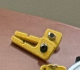
I have found two mirrorred parts I cannot identify and cannot remember that I dismantled them.
I did have a load of loose printed items that were simply around the machine, having to do with printing but maybe not necessarily to do with the Voron. Please anybody with a Voron, do you recognise these parts?
They have a M3 buttonhead and a profile nut on them. Judging by the orientation they are mirrors of eachother.
I checked the build instructions and cannot see them so…. questioning my sanity 🧐IMG_1615.jpeg
 
They hold the exhaust filter on.
Near the end of the assembly manual.
Sorry, I'm on my phone or I would give you an exact page number.
 
Despite the scorching temperatures I managed a bit of progress.

Clipboard 23 Jun 2024 at 12.31.jpeg
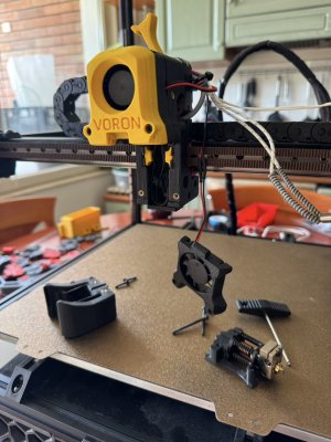
I had to completely dismantle the hotend since it was stopped while it suffered heat creep or something. So took it apart and cleaned out the filament path and installed a new nozzle.
Clipboard 23 Jun 2024 at 12.32.jpeg
Then finished the wiring and closed the base plate. Fitted handles and I thought I was ready for now.
Clipboard 23 Jun 2024 at 12.32.jpeg
But I had to remove the base plate again, twice, since I had forgotten the internet cable and then the power cable for the pi☹️
It is too hot 😬
 
I am done for today, and I think all is working as it should so far.
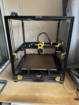
position.jpg
this is its final position
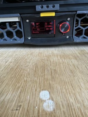
screen.jpg
Screen works too
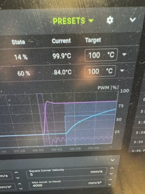
heaters.jpg
The machine homes and everything responds. All the fans work correctly and the heaters too.
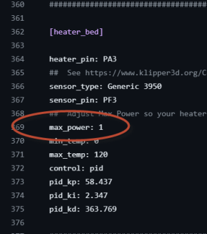
Just have to find how to correct that 60% for the bed, that is almost as bad as a 24V bed. Should start at full whack as far as I am concerned and then soften a bit as it approaches.
Happy as a lark. See what the week will bring, got more heat predicted and at work will be busy as hell so maybe when i come home I will not be in the mood or have no energy, we will see.
Once all works and it prints PLA then I will install all the panels and think of some way to guide my filament. I am not a fan of frame hangers for the reels, I have my own trolley next to the machine.
See you all later and wish me luck. So far it goes almost too good to be true ;)
 
I am not sure what you are saying is wrong with the bed?

Two things, you can change the % of power to the bed from .6 to 1 which is 100% power to it and then re-PID tune the bed. This can help you heat the bed much faster and is safe to do.
 
Nothing wrong with the bed, it is just very slow because it sits at 60% all the time. I don’t think that is needed with a cast tool plate bed. So I will search for this setting and change it.
 
Yup changed it, not having a mains powered heater for nothing.
So today did my first quad_gantry_level and it is mesmerizing to watch that happen.
Also tried a bed mesh and height graph but that failed because I had not done the gantry level first. Maybe this should be mentioned in the height mapping section or even on the console?
Anyway looked for ages for answers how to check and set z-offset and could only find answers related to octoprint while I use mainsail.
So in the end I simply risked a bedlevel print with my finger on the emergency button.
All went well so I take three points for the win 😬
Next what I want to do is to find this z-offset procedure, any tips?
Also if there is some list of all the commands you can do from the console, with explanation, that would also be a huge help.
So far loving the voron feeling, might have to do another gantry level before bedtime just to look at it before sleep 🤣😂Clipboard 24 Jun 2024 at 21.34.jpeg
The bedlevel print from an older, smaller printer 😜
 
From the Klipper docs https://www.klipper3d.org/Probe_Calibrate.html

"

Calibrating probe Z offset

Providing an accurate probe z_offset is critical to obtaining high quality prints. The z_offset is the distance between the nozzle and bed when the probe triggers. The Klipper PROBE_CALIBRATE tool can be used to obtain this value - it will run an automatic probe to measure the probe's Z trigger position and then start a manual probe to obtain the nozzle Z height. The probe z_offset will then be calculated from these measurements.

Start by homing the printer and then move the head to a position near the center of the bed. Navigate to the OctoPrint terminal tab and run the PROBE_CALIBRATE command to start the tool.

This tool will perform an automatic probe, then lift the head, move the nozzle over the location of the probe point, and start the manual probe tool. If the nozzle does not move to a position above the automatic probe point, then ABORT the manual probe tool and perform the XY probe offset calibration described above.

Once the manual probe tool starts, follow the steps described at "the paper test" to determine the actual distance between the nozzle and bed at the given location. Once those steps are complete one can ACCEPT the position and save the results to the config file with:

SAVE_CONFIG
Note that if a change is made to the printer's motion system, hotend position, or probe location then it will invalidate the results of PROBE_CALIBRATE.

If the probe has an X or Y offset and the bed tilt is changed (eg, by adjusting bed screws, running DELTA_CALIBRATE, running Z_TILT_ADJUST, running QUAD_GANTRY_LEVEL, or similar) then it will invalidate the results of PROBE_CALIBRATE. After making any of the above adjustments it will be necessary to run PROBE_CALIBRATE again.

If the results of PROBE_CALIBRATE are invalidated, then any previous bed mesh results that were obtained using the probe are also invalidated - it will be necessary to rerun BED_MESH_CALIBRATE after recalibrating the probe."


Now, what I do is create or use a single flat model to print and in Mainsail you will see the Z offsets and I fine tune it there, by making the first layer super flat to the touch and visually looking at it while it prints. Then that same section has a SAVE. Hit that and then One more Save_Config to have it retain the Z offset.
So if my bed level print was almost ok, you would reprint that thing and babystep it from that offset section in mainsail? Then if all is fine do a new save from the same section?
Did I understand that correctly?
Obviously this changed the cfg files so a new back up would also be required.
 
So if my bed level print was almost ok, you would reprint that thing and babystep it from that offset section in mainsail? Then if all is fine do a new save from the same section?
Did I understand that correctly?
Obviously this changed the cfg files so a new back up would also be required.
Yes, you have it correct. I seem to answer this one a lot so I might create a small document on my process.
 
Yes, you have it correct. I seem to answer this one a lot so I might create a small document on my process.
If you do, please consider also including advise on whether one should do a quad_gantry_level before running any of these calibrations. Obviously mine wasn't totally square after building yet, and when I tried running a bed height graph it came out utterly wrong due to not having leveled the gantry first. TBH I expected this to be included in the command but clearly it is not. Maybe it would be wise to do the same before doing any of the probe calibrations since these would also be negatively affected by a gantry not being level yet. Basically every time the motors power down this would be needed IMHO.
 
You should do the QGL before the bed mesh for sure. If it's not set this way then you can do it in your Startup macro.
 
I had something strange happen, and I am sure I did not do anything out of the ordinary.
I followed your babystepping advise and when I was happy I saved this to config. The klipper restarted as expected, and I homed, did a QGL and reprinted my bed level gcode file. Suddenly it printed between 5 or 6 mm in the air!!!!!! I never made that much of an adjustment and the print without my babystepping was almost correct. I adjusted just 0.015mm further from the bed for smoothness.
So I then had to go through the whole probe_calibration thing and the manual paper test, now it is ok again. Really strange.
As a side note, I found myself in two minds about the instructions of the paper test. When you do the probe_calibration command, it fetches the probe and does the bed touch thing. Then it moves the nozzle over the same position, and waits while onscreen you have the measurement screen with your adjustment buttons.
Thing is the instructions tell you to check the nozzle to the bed with the paper, but this probe attachment is still on and it does not tell you your should remove it by hand and proceed without it attached.
I concluded you should remove it and this proved right. But I really feel these instructions could make that clearer.
What do you think?
I am not sure I follow what you are saying.
Is the probe you use detachable? Like Klicky or something. I think there are some many combinations of different probes what you are reading is a general statement.

I for example use a Beacon probe.
 
I am not sure I follow what you are saying.
Is the probe you use detachable? Like Klicky or something. I think there are some many combinations of different probes what you are reading is a general statement.

I for example use a Beacon probe.
Yes it is detachable and has its own pocket where it lives. It is held with magnets and uses a small limit switch as a probe.
Sorry for the confusion, I didn’t think about all the others.
It also has an off bed nozzle probe where it homes the nozzle.
 
Yes it is detachable and has its own pocket where it lives. It is held with magnets and uses a small limit switch as a probe.
Sorry for the confusion, I didn’t think about all the others.
It also has an off bed nozzle probe where it homes the nozzle.
I see, you are talking about a klicky probe or variant of the klicky. That is non standard, hence the confusion.
 
So what is standard originally?
In the end, with combined luck and logic, it worked fine so it is not like I should complain about it at all. It was just a moment of contemplation and self doubt during the learning curve.
It is totally up and running and as we speak I am printing a plaque for my Harley Knucklehead engine. I have also printed my 100x100x100 X-Y-Z calibration cross to see how accurate it is and it is damn nice already. X and Y are bang on size while the Z had a tiny little blob on the solid infill that made it 100.3mm but on the perimeters it is also bang on 100. Rather happy with that since I mainly print technical working models and prototyping stuff, size is very important to me with loads of bearing fits and tolerances.
 
Top