Hi All
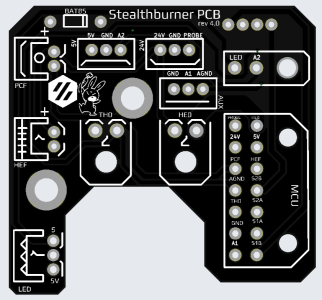
I'm in the middle of a big upgrade of my Voron 2.4v1 including, changing the toolhead to a Stealthburner, adding a Stealthburner Toolhead PCB by HartK (single piece, V4), swapping fron a Klikky Probe to a Voron Tap (Chaotic Labs CNC Tap v1), and changing to an Octopus Pro board. So a lot of moving parts, literally.
I'm at the stage where I'm testing the system works correctly and in the main all is ok, but having issues with getting the tap working. I've read a lot of posts/advice here and other sources, and consequently tried lots of things, but no one seems to quite describe my issue (or so it seems).
A couple of things to note up front ...
1) The Chaotic Labs CNC Tap (v1) uses a switch called an Omron D2FP-FN2 (I think). I'm honestly, not sure how it it being used as I expected it to be like the X/Y end stop switches (and old Z end stop), so its wired NO and sends a signal when triggered. I can't get my head around the need for a 5v, GND and Signal cable. Which leads me to ...
2) The Stealthburner PCB, is vrsitile in config. so that you can simply plug in the Standard Omicron Probe, and it has a dedicated 24v socket for that. However, next to that is has a 5v socket, which you hve to use for the switch. It matters because you are running your signal lead from A2 and not Signal.

I'm fairly sure my wiring is correct, up to and comming out of the PCB. I need to do a Continuity Test on the switch somehow to confirm a few things, but I think it's right.
The only wire to worry about is A2, which goes off to PG15 on the Octopus Pro Board. The config. has been updated per the Voron-Tap Github page.
What I'm trying to do is just test the Z so that I can see the switch triggered/untriggered.
Does anyone have a similiar set up and I can compare notes?
p.s. this driving me nuts!
I'm in the middle of a big upgrade of my Voron 2.4v1 including, changing the toolhead to a Stealthburner, adding a Stealthburner Toolhead PCB by HartK (single piece, V4), swapping fron a Klikky Probe to a Voron Tap (Chaotic Labs CNC Tap v1), and changing to an Octopus Pro board. So a lot of moving parts, literally.
I'm at the stage where I'm testing the system works correctly and in the main all is ok, but having issues with getting the tap working. I've read a lot of posts/advice here and other sources, and consequently tried lots of things, but no one seems to quite describe my issue (or so it seems).
A couple of things to note up front ...
1) The Chaotic Labs CNC Tap (v1) uses a switch called an Omron D2FP-FN2 (I think). I'm honestly, not sure how it it being used as I expected it to be like the X/Y end stop switches (and old Z end stop), so its wired NO and sends a signal when triggered. I can't get my head around the need for a 5v, GND and Signal cable. Which leads me to ...
2) The Stealthburner PCB, is vrsitile in config. so that you can simply plug in the Standard Omicron Probe, and it has a dedicated 24v socket for that. However, next to that is has a 5v socket, which you hve to use for the switch. It matters because you are running your signal lead from A2 and not Signal.

I'm fairly sure my wiring is correct, up to and comming out of the PCB. I need to do a Continuity Test on the switch somehow to confirm a few things, but I think it's right.
The only wire to worry about is A2, which goes off to PG15 on the Octopus Pro Board. The config. has been updated per the Voron-Tap Github page.
What I'm trying to do is just test the Z so that I can see the switch triggered/untriggered.
Does anyone have a similiar set up and I can compare notes?
p.s. this driving me nuts!

