What's new
VORON Design

Register a free account today to become a member! Once signed in, you'll be able to participate on this site by adding your own topics and posts, as well as connect with other members!

Formbot Voron 2.4 R2 "Pro" 350 Kit build

Ytrahcodo

Member
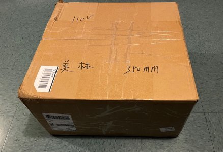
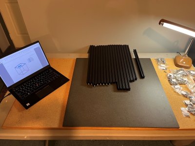
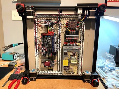
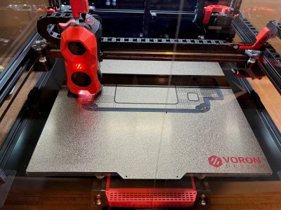
Just finishing up my first Voron build. Ordered the Formbot 2.4 R2 "Pro" 350 Kit direct from the Formbot site on 1/05 (US delivery) and received everything on 1/10.
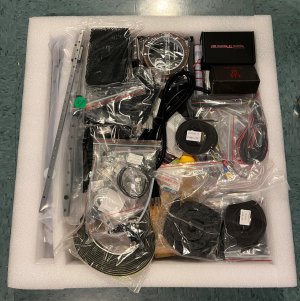
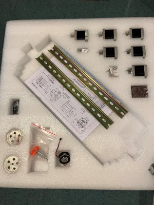
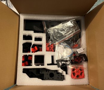
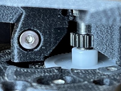
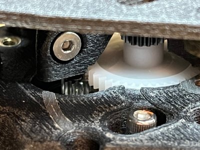
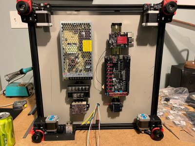
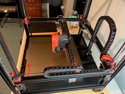
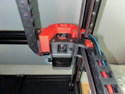
Started unpacking on 1/11. The Formbot PRO Kit includes a lot of the current common upgrades such as TAP, Nevermore, toolhead PCBs, ACM deck, and 5" HDMI screen. So I also purchased the complete printed parts kit from Formbot since it included all the parts for this non-standard build. Printed in ABS/GF, comes in any color you want as long as it's red.
 

Attachments

  • VB1.jpg
    VB1.jpg
    364.9 KB · Views: 60
  • VB3.jpg
    VB3.jpg
    700.7 KB · Views: 43
  • VB4.jpg
    VB4.jpg
    994.6 KB · Views: 39
  • VB7.jpg
    VB7.jpg
    445 KB · Views: 36
  • VB2.jpg
    VB2.jpg
    359.6 KB · Views: 39
Had the frame assembled and squared up on day 1. I had some huge 24" x 24" thick rectified porcelain tiles on hand that are very flat, so one of these served as my frame build surface during the squaring stage.
 

Attachments

  • VB8.jpg
    VB8.jpg
    373.4 KB · Views: 37
Day 2 - 1/11:
Got the Z motors, idlers, and Z rails installed. Had to print the rail alignment tools first on my old CR10 before tightening the rails. So far everything was straight-forward, by the book.
 

Attachments

  • VB9.jpg
    VB9.jpg
    396.2 KB · Views: 41
Day 3 - 1/14:
Assembled the Clockwork 2 extruder and Stealthburner. This was a bit more complicated since the Formbot version of the SB has some differences due to their custom toolhead PCB and parts choices.
The gears they provided for the CW2 didn't mesh properly at first. The stepper pinion gear barely engaged the 50 tooth extruder gear. I don't know who they sourced this from but it's not right. Not the fault of the extruder case. I had to heat the shaft of the extruder gear to soften the grip on the gear enough so that I could move it on the shaft for better engagement. Not perfect, but it will do for now. I may end up replacing this later.

Day 4 - 1/15:
Got the gantry assembled, belts installed and adjusted, and the SB with TAP installed.
 

Attachments

  • VB13.jpg
    VB13.jpg
    344.5 KB · Views: 45
  • VB11.jpg
    VB11.jpg
    375.1 KB · Views: 46
  • VB16.jpg
    VB16.jpg
    372.4 KB · Views: 58
Day 5 , 6 - 1/18, 1/20: electrical installation and wiring.
Instead of a Raspberry PI, the Formbot kit comes with a Bigtreetech "BTT PI". I would have rather they left this out and saved me the the money since I already have a spare Raspberry PI 3, but I guess it's only about $30 anyway. The other downside is you have to use their custom BIQU PI image. This required a lot of fussing with the software that wouldn't have been necessary if it was a real PI. Also, I'd feel better, more secure, with a generic PI OS running on a standard board. May change this out later.

The wiring stage took the longest, due to so many customizations that I had to research. There's virtually no documentation from Formbot specifc to all the non-standard options that come in this PRO version kit. I probably spent more time researching the installation of these than I did actually on the assembly. Fortunately all the wire harnesses were pre-made, well labelled, and fit well - if you follow their style of component placement.

There's no separate 5V power supply in this kit. Both the Octopus and the BTT PI each have their own on-board 24V to 5V DCDC converters. The breakout board is a nice touch to simplify the gantry wiring.
 

Attachments

  • VB18.jpg
    VB18.jpg
    448 KB · Views: 83
  • VB20.jpg
    VB20.jpg
    520.6 KB · Views: 84
  • VB25.jpg
    VB25.jpg
    436.3 KB · Views: 71
  • VB26.jpg
    VB26.jpg
    273 KB · Views: 66
Last edited:
It's been several days now of software installation, config files tweaking, and basic tuning. But it's running now, YAY!
After a couple failed attempts to get something to stick to the PEI build surface, it printed it's first Benchy, which came out nice considering I haven't done any input shaping tuning yet.
I'm already putting it to work making some parts for itself. Printed a wiring cover for the rear exhaust fan wires. Now starting on a real project in ABS that defeated me on my old CR10, and why I need a 350...
 

Attachments

  • VB22.jpg
    VB22.jpg
    696 KB · Views: 69
  • 1st benchy.jpg
    1st benchy.jpg
    55.2 KB · Views: 74
  • panel.jpg
    panel.jpg
    357.8 KB · Views: 73
Hello! how did you solved the problem with printer cfg? i'm still trying, and if you have some extra photo with wiring of ldo board
 
Which problem are you asking about?
In general, I was able to find various configuration examples scattered around the web and patched them together with some edits for my particular printer.
Regarding "wiring of ldo board", this was a Formbot kit. It didn't have any boards from LDO.
 
Day 5 , 6 - 1/18, 1/20: electrical installation and wiring.
Instead of a Raspberry PI, the Formbot kit comes with a Bigtreetech "BTT PI". I would have rather they left this out and saved me the the money since I already have a spare Raspberry PI 3, but I guess it's only about $30 anyway. The other downside is you have to use their custom BIQU PI image. This required a lot of fussing with the software that wouldn't have been necessary if it was a real PI. Also, I'd feel better, more secure, with a generic PI OS running on a standard board. May change this out later.

The wiring stage took the longest, due to so many customizations that I had to research. There's virtually no documentation from Formbot specifc to all the non-standard options that come in this PRO version kit. I probably spent more time researching the installation of these than I did actually on the assembly. Fortunately all the wire harnesses were pre-made, well labelled, and fit well - if you follow their style of component placement.

There's no separate 5V power supply in this kit. Both the Octopus and the BTT PI each have their own on-board 24V to 5V DCDC converters. The breakout board is a nice touch to simplify the gantry wiring.
Very roomy. I have the 300x300 and it is pretty tight in the electronics bay. Ditto on the research comment.
 
Ytrahcodo, is it possible for you to post pictures of where you mounted the Toolhead PCB and Fan Adapter PCB? Finally building the stealthburner and know they go on that assembly. Thank you!
 
Top