- Printer Model
- Switchwire
- Extruder Type
- Clockwork 1
- Cooling Type
- Stealthburner
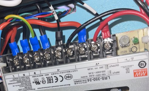
I’m having some trouble with this tool headboard. It seems like it does not have the X is that wire running all the way down to the motherboard I believe they have it marked as the heated enclosure thermistor. Also, all of the inserts only have one wire going to them. Is there a common ground from the two headboard to the motherboard, or to the power supply, if anyone has any knowledge installing this board on the printer, please let me know. I have an SKR mini E3 V3.