Stadi
New member
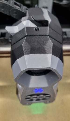
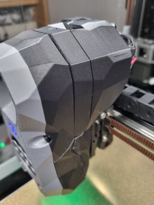
Hello in the new forum, I'll start with a question. Since I converted to TAP, my SB has a gap between the CW2 and the cover.
At first I thought it was because all the parts were printed from PA12CF and the dimensions might therefore differ from the ABS parts. Now I've reprinted everything from ASA CF but the gap is still there. Anyone have an idea what could be the reason for this? I can't see anywhere that something is not mounted as it should be according to the instructions. Everything works great, so it's just an optical thing
Best regards