What's new
VORON Design

Register a free account today to become a member! Once signed in, you'll be able to participate on this site by adding your own topics and posts, as well as connect with other members!

My first build - Voron V0.2S1 (LDO kit)

Chipj

Member
Introduction: After a lot of consideration, I decided on New Years Eve to take the plunge and try a Voron kit. I chose an LDO V0.2 kit. I don't currently own a 3D printer, and understand that a Voron build is not recommended as a first experience. But I'm up for a project! The kIt (LDO Voron V0.2-S1) arrived the first week of the year. I'm spending more time building than posting, so am only now making my first post. The first hurdle was the recommended "no drop nut" mod. I ended up printing a bunch of these at a local maker space -- this was a learning experience in itself. I printed in PLA, which was all that was available to me at the maker space. I am hoping PLA will hold up well enough, since these are just holding the nuts in the extrusions. Perhaps I'll reprint in ABS after the printer is done.

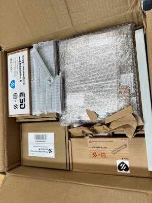
The kit arrived well packed, as did the printed parts, which I bought at the same time as the kit.

LDO V0.2 kit in box.jpeg
 
Good luck! The LDO kit is very good. Take your time and follow the instructions carefully--especially checking, double-checking, and triple-checking the nut preloads. Once you get to the electronics, read the LDO doce very carefully in addition to the Voron docs.
 
After being sick a few days, and making no progress on the kit at all, I got back to it. I got back to the local maker space, and finished printing the ~110 or so "No drop nut" pieces which are recommended in the LDO documentation (and YouTube videos I've watched).

Lots of no drop nuts populated with M3 nuts.jpeg

I finally began the build process proper by stripping the rails of the shipping grease by soaking in 90% Isopropyl alcohol from the drug store overnight. I then dried them, and squeezed as much Shell Mobiluxe EP-2 grease into the bearing carts as I could manage.

While the rails were drying, I began looking through the printed parts I'd gotten from MatterHackers to see if I could find the rail installation guides. (Could these also be optional mods?) I ended up going through all the printed parts I'd gotten from MatterHackers. After matching the printed parts with the included bed layouts from MH, I recorded on the inventory sheet the bag where the part was found, and put it back in the original bag. I hope this helps when it comes time to find the part again. And I did indeed find the rail guides. I’m a little confused about the Kirigami bed parts, as some are marked as "LDO" parts and some are not in the parts manifest. I hope this becomes clearer as I proceed. And it looks like there are parts for several different hot ends, including the Revo hot end I got with the kit. So there are going to be some unused parts.

Also while the rails were drying, I labeled all the extrusions with painter's tape, in order to (hopefully) avoid confusion later. My future self really appreciated this.

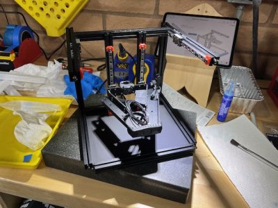
I then mounted the Z rails to the extrusions, and built the Z frame with temporary "H" extrusions to help square the frame. The grey platform in the photo is a machinist's surface plate I had around the shop. It seems big enough to build on for now, and should help to keep things square as I buildZ rails installed.jpeg.

This seemed like a good stopping point. The next step will be the Kirigami bed.
 
I did the mechanical assembly of the Kirigami bed. The LDO instructions said to check the bed carefully for levelness. I did, and found no issues. I mounted the bed to the Z rails, and did lots of "tramming" and adjustment of the Z rails to ensure it moves up and down easily. I ended up with a bed which doesn't descend the rails just by force of gravity. But there are no "tight spots" in the travel, either. And everything still looks square.

Bed mounted with no Z end stop.jpeg

I then spent over an hour trying to find the Z end stop in my printed parts, and the Z end stop switch in the kit. Apparently, looking at my notes on the printed parts paperwork isn't as good as looking at the printed parts themselves -- the end stop was there in the bag. I found the Z end stop switch in the "cables" box, already soldered to the cable. I thought having this pre-soldered was a pretty neat feature of the LDO kit.

I mounted the Z end stop and switch, and called it a night.

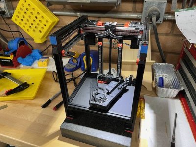
The next day, I removed “helper” “H” extrusions from Z axis frame assembly, and preloaded lots of nuts with “no drop nut” mod in PLA. Added “E” extrusions with the Y rails, and “H” extrusions to the back of the frame. During this process, I canted the Z frame into a parallelogram, and resquared it. I hope the all the other frame extrusions will help keep things square. Re-trammed and re-trammed, and remeasured center for the Z rails with dial calipers. At one point, I loosened the Z rails a bit from the extrusions in order to better space things. This may not have been necessary — I’m trying to be very precise in tolerances, and am getting to the 1/10 of a millimeter in tolerances. (The bed still moves smoothly.) Finally, installed the deck panel. Left the bottom “B” extrusion loose, and stopped here. I’ll re-check all the nut preloads when I start tomorrow.

Partial frame with Y rails.jpeg
 
Started the day by doing a final "nut check" prior to closing the frame. I included extra nuts for the "Nevermore" filter, which I think I'll add later. Then I added the extrusions to close the front of the frame, and spent some time loosening screws and readjusting so that everything so far is square and coplanar.

After a nice cup of tea, I began work on the A and B motor assemblies. I found that using a piece of painter's tape to keep the screws for the bearing stacks from falling out was helpful. I only spilled the bearing stacks a couple of times. I think I found a typo in the manual (p. 78) -- the pulley's bottom of the belt race is much less than 17.5 mm from the motor. But the "Frankenjig" worked well for setting the pulley height.

I then assembled and installed the A/B idlers. It's looking more like a printer!

AB motors and idlers installed.jpeg

I then assembled the feet, including the runout sensor assembly on the right rear foot. I broke the Bowden fitting while installing it in the right rear foot. After spending more on glue than a new part cost, I found a replacement on Amazon -- $8 for 10 new fittings. The LDO kit included a cable pre-soldered to the microswitch for the runout sensor. The cable was soldered to the "normally closed" (outer) terminals of the switch, and the manual says "...soldering wire to the two outer terminal. This will setup the switch in a Normally Open state which is preferred for this type of use case." Hmmm.... A multimeter confirms that the outer terminals of the switch are the "normally closed" terminals. But it looks like the switch is normally activated when a piece of filament is present -- is this what the manual means by "normally open"? After thinking about it for a while, I decided to keep the cable soldered to the outer (normally closed) terminals of the switch. My thinking is that if I later want to disable the runout sensor completely by unplugging it, that the unplugging will mimic the presence of filament in the sensor.
 
Next step was the A/B belt install and tensioning. I discovered that the belts need to be slightly loose through the X carriage in order for the tensioner knobs to work. I then spent hours spread over several days trying to get both belts within about 1/2 hertz of each other, and close to 110 hertz when I plucked them. I learned that:
  1. The belt tensions change when tightening the motor screws.
  2. The adjustments for the A and B belts are not independent. Adjusting tension in one affects the tension in the other.
  3. Moving the X carriage around its range of motion after a belt adjustment is good to do prior to re-measuring the tension.
  4. It's easy to get the belts so tight when initially attaching them to the X carriage that the tensioners can't reduce the tension to the desired value.
I'll probably remeasure tension in a few days, just to see if things change. But I'm really glad to call this part of the build complete.
A-B belts installed and tensioned.jpeg
 
Today I installed the print bed and the cable chain. This was pretty straightforward, though I had to refer to LDO instructions for installing the "Kirigami Installation Guide -- Installation during a V0 Build" as well as "Kirigami Bed for Voron V0.2+". (Greg's Maker Corner build series was very helpful as well.) The cables in the LDO kit are pre-crimped and cut to length -- this was a very nice feature. All I had to do was to insert crimped ends into the connector shells after feeding the wires through the cable chain.

Build plate installed.jpeg
 
I started work on the extruder. I got as far as installing the fans before finding that instead of hot end fan 3010, I had a 3006 (5V) fan, with “HEF” on the cable label. Later, I found another 3010, also with “HEF” on the cable label. I removed the right side part fan to get to the hot end fan, and replaced the 5V (3006) fan with the 24V (3010) fan. I guess I’ll have extra fans. I also found another typo in the manual — pg. 170, “Anti-squish thingymajig doesn’t say what size screw should be there. The CAD files show it is a M2x6 FHCS, so that’s what I used.

After a bit of fiddling around (with magnifying glasses) to get the extruder gear backlash adjusted, I then installed the extruder motor. Following the manual, I rechecked that a piece of filament in the extruder gets light tooth marks on it after passing through the filament path. I then installed the hot end into the extruder assembly. I'm using the "stock" Revo hot end.

The next step will be to install the Picobilical board on the extruder, but I'll save that for tomorrow.

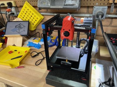
Here's the completed extruder assembly:
Extruder complete.jpeg

I also discovered in my after hours reading a couple of other phone apps which measure frequency. I downloaded "Carbon Drive" and "Sound Spectrum Analysis". I found the "Carbon Drive" app, set on "Motorcycle", was much easier for me to use for tuning the A/B belts. I rechecked the belts, and am satisfied with where they are. (Both belts at 109 Hz., manual recommends 110 Hz.)
 
Installing the Picobilical board and the extruder assembly to the gantry was much easier than I'd imagined it would be. A few screws and connecting some wires, and the job was done. The labeling of the wires in the LDO kit was very helpful, as were the photos in the instructions.

The next step will be to begin mounting electronics and wiring.

Extruder and Picobilical.jpeg
 

Attachments

  • Extruder and Picobilical back.jpeg
    Extruder and Picobilical back.jpeg
    100.8 KB · Views: 1
I placed the mid-panel, and began looking at the layout of the SKR Pico and the Raspberry Pi 4B that I purchased. The RP is not the Raspberry Pi Zero 2W which the LDO instructions seem to be assuming. My RP and the SKR Pico take the same RP mount, but only one mount and VHB DIN mount were included in the MatterHackers printed parts. And this is all that I see called out in the printed parts list in the GitHub.... Hmmmm. It would be really great to have two VHB DIN mounts and two RP/SKR Pico mounts, instead of just one.

I looked at this for a while, and tried to see if any of the other mounts in the printed parts I got would work. There are a lot of parts for electronics mounts, but none would work with the RP 4 hole pattern. I decided to go to my local maker space to print the mount and VHB DIN mount in PLA, with the intent of reprinting them in ABS once the printer is complete, and I can print in ABS.

Thinking about this later, I decided to search for DIN mounts available commercially. Amazon had 4” long aluminum DIN rails, available for next day delivery, for $6. I hit the “buy” button -- these are cheap enough to throw away if they don't work. If they do work, I won’t have to worry about getting a PLA DIN mount dislodged from VHB tape in order to replace it with ABS.

When the he Amazon DIN rails arrived, I found they fit the printed DIN clips just fine, though I had to trim the lengths. But they’re about 1mm taller than the printed parts. I think the printed VHB DIN mounts are a bit thinner to account for the thickness of the VHB tape which would be used to mount them. I think I can keep the design height by just drilling the mid plate and screwing in the aluminum DIN rails. I also tried a commercially available Raspberry Pi DIN mount, but this raised the Pi so far the back panel wouldn't be able to be installed.

Finally, I had the idea of asking MatterHackers if they could do a custom print of another DIN mount and rail. MH was quite helpful, and printed the extra parts I needed quite cheaply. I also had them print the Mornsun PSU cover, which is an optional printed part for the LDO kit. The printed parts arrived in two days. I decided to keep the aluminum DIN rails, even though mounting them required drilling a couple of extra holes in the mid-panel.

I also decided that I wanted to mount the PSU with screws rather than VHB tape, primarily because I wanted to be able to remove the PSU more easily later. To find where to drill the holes, I placed a sheet of paper on the bottom of the PSU, and rubbed it with a pencil. The screw locations show nicely in the pencil rubbing, and the paper became my drilling template. I did have to go to the hardware store for screws, as the holes in my Mornsun PSU take M4 screws.

With everything now mounted, I routed and connected the wiring. This went pretty well. I found that a pair of dikes cuts the cable channel more easily than a jigsaw or a hacksaw, and is a cleaner cut to boot. Everything is now connected except for the power to the Raspberry Pi, which has me scratching my head a little.
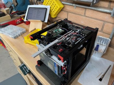
Mostly wired.jpeg


I'm quite fortunate to have a quality control inspector purring at the assembly progress.

Quality control.jpeg
 
I went down a rabbit hole with the Raspberry Pi power. I wondered about, researched, and thought for several days how to power my Raspberry Pi 4B power in a Voron 0.2 . I didn't see any instructions specific to using Raspberry Pis other than the Raspberry Pi Zero 2W. My research revealed that I should not be relying on the USB data cables from the SKR Pico to supply power for the Pi, and I didn't try to do this. There's a USB-C connector on the side to bring power into the Pi, but that assumes 5V somewhere to supply the other end of the cable. And I wasn't enthusiastic about butchering a USB-C cable in order to get 5V to the Pi. The LDO kit instructions talked about a header which was supplied with the Pi if you got one with your kit -- but I didn't. And the instructions seem to show the "included" RP option is a Raspberry Pi Zero 2W. The best option seemed to be to power my Pi via the GPIO pins. So I started thinking about a header to connect to them, and where to draw 5V from.

I remembered a cable in the Picobilical box which came with the kit -- it was marked "5V" on one end, and "To RPI" on the other. OK -- at least I don't have to make one end of the cable, assuming I can draw power the Raspberry Pi 4 from the Picobilical frame card or from the SKR Pico. And then I took a look at what was inside the unopened anti-static bag in the Picobilical box. It was a board with GPIO header, and power terminals. I wished I had looked in this bag a few days ago. I checked connections on the board with a multimeter, and the power terminals do connect to the correct GPIO pins. Clearly, this was intended for the Raspberry Pi Zero 2W. Would it work?

I did a bit more research. Raspberry Pi Zero 2W draws 2.5A. Raspberry Pi 4B requires "5V DC via GPIO header (minimum 3A*)". And the current supplied by the Picobilical frame card is 5A. Yahoo! The LDO kit really included everything I needed! Just connect the power cable from the Picobilical to the GPIO header, and plug the header into the RP.

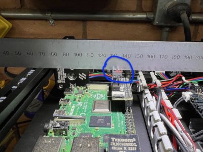
Unfortunately, with the aluminum DIN rails I'd decided to use, the GPIO header card was just a fraction of a millimeter too tall for the back panel to close:
A little too tall.jpeg

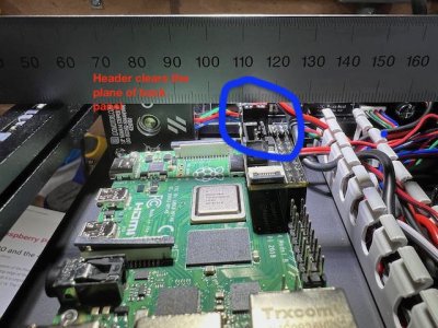
So I removed the aluminum DIN rail on the left side of the mid-panel, and went back to the "stock" option of a printed ABS VHB DIN rail. This was about 1 mm. shorter than the aluminum DIN rail, and that was enough for the header card to clear:
Clears when using printed VHB DIN rail.jpeg

The kit is now completely wired. I powered it on, and no smoke came out. And the lights on the circuit boards came on. Hooray!

Next step will be installing firmware.
 
It is now time to install firmware. I moved the printer indoors in order to have a more comfortable seat while I worked. Mostly, this was following the instructions in LDO firmware installation instructions. Although the instructions indicate you may be able to install the Picobilical frame board, apparently the board I had did not already have firmware on it. So it had to be unplugged and connected directly to my laptop in order to load firmware. This step was just a little confusing, because the instructions for SKR Pico and for the Picobilical frame board are quite similar -- but it *is* two separate installs. I ended up spending a couple of days on this part before getting it right.

I continued with the configuration in the printer.cfg file. Using the example printer.cfg from the LDO GitHub was a very good starting place.

From this point, the LDO instructions point you to the Voron initial configuration checks at https://docs.vorondesign.com/build/startup/. All the motor tests went OK without having to adjust the polarity in printer.cfg. I went through the Z endstop calibration, heater calibration, and PiD tuning, bed leveling, and sensorless homing setup. And then I decided to stop, because the printer enclosure isn't installed yet, and I thought this might affect calibration of heaters and PiD tuning.

I installed the (optional) display, as well as the skirts and bottoms, back and side panels. At this point, I installed the display firmware, using instructions at https://github.com/VoronDesign/Voro...lay/Documentation/Setup_and_Flashing_Guide.md. And I added V0Display.cfg to my printer.cfg file. The display now works, and is nice to have. However, I think I'll still mostly use a web interface on an iPad or laptop.

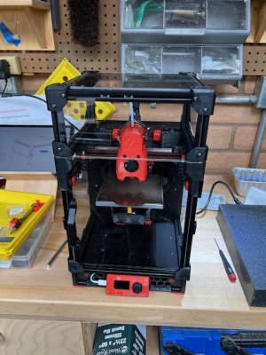
Here's the progress with the display installed:
Display and sides installed.jpeg
 
The last part of the assembly was adding the top hat. This was very straightforward. I redid the PiD calibration for the bed and hot end, now that the printer is enclosed. I'm not sure this was necessary, but it couldn't hurt. I decided to skip the recheck of bed leveling and Z endstop calibration since the printer was now warm, and these are supposed to be done with the printer cold.

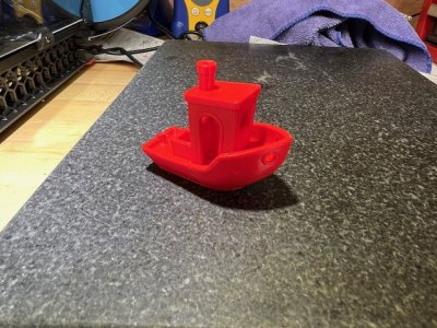
I then tried to extrude some PLA filament, and discovered I needed to reverse the sense of the extruder motor by adding a "!" to the extruder direction in my printer.cfg file. This was the first motor I had to do this for -- the A, B, and Z motors were all moving in the correct directions from the start. I set a Voron 0 profile in Cura, sliced a Voron calibration cube, and printed. I also tried a benchy. I think the results are pretty good!

First Voron calibration cube.jpegFirst benchy.jpeg


Later on I tried a calibration cube and some optional printer parts in ABS, using the midpoints of extruder and bed temperature ranges printed on the spool of filament. This also looked pretty good.

Voron calibration cube ABS.jpeg

While I'm sure I'll be tweaking and improving the printer for a while, at this point, I'm calling the build complete.

This was not only my first 3D printer build, but also my first 3D printer, and I’ve learned a lot. Some of this was by going to my local maker space to print “extras” like the “No drop nut” mod for the printer. But most of my learning was from reading about and building the printer itself. I get much more education by “doing” than I do by “reading”.

The LDO kit was great, and I’m glad that I chose it. It seemed that every time I thought I’d hit a roadblock, I discovered something included in the kit which helped get me around the roadblock. Though there were a couple of times when jumping between instructions for the LDO mods and the main Voron assembly manual required some “head scratching”, it was nothing which I couldn’t figure out. I think it’s great that a newbie like me is able to jump into something like this and be successful. I’m grateful for all the work the Voron team has put into the design of this printer and the instructions, and for LDO for putting together such a good kit.
 
Top