What's new
VORON Design

Register a free account today to become a member! Once signed in, you'll be able to participate on this site by adding your own topics and posts, as well as connect with other members!

My first Voron - based on fysetc Voron Trident-Kit

Jerlin

Member
Hello to everyone!

I got myself a nice christmas present, a Voron Trident 300 Kit by Fysetc.
The build went straight forward, all thanks to the documetation.
It was my first printer kit, but i already own an Ender 7, which I slightly modified (Klipper+Klipperscreen, Mosquito Hotend, drag chain)
After 4-5 days, I spent about 35 hours I got my Voron running and named him "Newton".

Tank you very much Voron Design Team!

A few picture of the process are attached.
The side panels, doors and bottom cover are going to be mounted, when I installed the chamber light and webcam. The parts are still in shipment.

Just a few specs:
  • Fysetc Spider 2.2
  • Fysetc TMC2209
  • Phaetus Dragon HF
  • RPi 4 running Klipper
  • BTT TFT50 will be added for Klipperscreen
Planned upgrades / modifications
  • BentoBox or evermore filter
  • chamber rgb light
  • webcam
  • exhaust and electronics fan controlled via temperature probe
  • maybe toolhead can pcb and toolhead led
  • and for sure, tuning, playing and (maybe) some usefull prints 🙃
Last, but not least, another huge thanks to the Voron-Team!

Jan from germany

newton.jpg
 

Attachments

  • bolts_nuts.jpg
    bolts_nuts.jpg
    189.9 KB · Views: 15
  • wow_stick.jpg
    wow_stick.jpg
    146.4 KB · Views: 14
  • Spider22.jpg
    Spider22.jpg
    213.6 KB · Views: 15
  • rails1.jpg
    rails1.jpg
    124 KB · Views: 18
  • misc1.jpg
    misc1.jpg
    187.7 KB · Views: 18
  • Frame.jpg
    Frame.jpg
    155.7 KB · Views: 17
  • extrusions.jpg
    extrusions.jpg
    143.7 KB · Views: 15
  • electronics.jpg
    electronics.jpg
    221.9 KB · Views: 14
Hello again,

I want to give an update about my "Newton":

  • The electronics compartment has its own thermistor
  • RGB lights, check
    I used 45° aluminium extrusion with custom printed mounting caps
  • webcam, check
    the mount is not final, I am not really happy with the angle
  • chamber thermistor, check

    wansview.jpg

  • Just for convenience I adde an USB port to the front

    usb.jpg
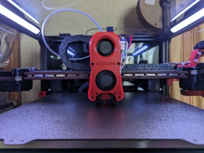
  • AB-NB Toolhead for that extra bit of cooling and fysetc mellow toolhead can board

    ABBN.jpg

    Unfortunately, one gantry bracket broke, so i have to replace it soon. For now it is printing fine and it seem more or less cosmetic.

Greetings from Germany
Jan and his Newton
 
What webcam are you using and the chamber and electronic thermistor are they connected to your controller board and they show up directly in klipper can you share the printer cfg for the added thermistors. Also where and how you mounted them in chamber and electronic compartments.
 
I'm using a "wansview webcam 1080p 102". Just a generic marketing name, the 102 seems to be the model number. (The ASIN is "B087M6YNYF", I'm not sure if links to amazon are allowed here)

The thermistors are connected to the spider controller board, they are specified via "fan" and shown in the temperature chart of mainsail.
For the electronics compartment I shortend the wire to 1-2 cm and did not mount it. It is just held in by the connector.
For the chamber I made my own mount for a 20x20 extrusion. It is a simple and kind of stupid design, because I have to feed the wires through before I crimp them. I will do a redesign, if the sensor needs to be replaced.

[temperature_fan electronics]
## electronics fan - FAN2
pin: PB2
kick_start_time: 1 #0.5
max_power: 0.75
#cycle_time: 0.010
shutdown_speed: 0
control: watermark
max_delta: 3
min_temp: 10
max_temp: 65
target_temp: 30
sensor_type: Generic 3950
sensor_pin: PB1

[temperature_fan exhaust_fan-Chamber]
## Exhaust fan - In E2 OUT
pin: PB3
kick_start_time: 1 #0.5
max_power: 1
shutdown_speed: 0
control: watermark
max_delta: 0.5
sensor_type: Generic 3950
sensor_pin: PC3
min_temp: 10
max_temp: 75
target_temp: 45
 

Attachments

  • image001.jpg
    image001.jpg
    81.2 KB · Views: 3
  • Bild_2024-03-12_202706964.png
    Bild_2024-03-12_202706964.png
    56.4 KB · Views: 3
I'm using a "wansview webcam 1080p 102". Just a generic marketing name, the 102 seems to be the model number. (The ASIN is "B087M6YNYF", I'm not sure if links to amazon are allowed here)

The thermistors are connected to the spider controller board, they are specified via "fan" and shown in the temperature chart of mainsail.
For the electronics compartment I shortend the wire to 1-2 cm and did not mount it. It is just held in by the connector.
For the chamber I made my own mount for a 20x20 extrusion. It is a simple and kind of stupid design, because I have to feed the wires through before I crimp them. I will do a redesign, if the sensor needs to be replaced.

[temperature_fan electronics]
## electronics fan - FAN2
pin: PB2
kick_start_time: 1 #0.5
max_power: 0.75
#cycle_time: 0.010
shutdown_speed: 0
control: watermark
max_delta: 3
min_temp: 10
max_temp: 65
target_temp: 30
sensor_type: Generic 3950
sensor_pin: PB1

[temperature_fan exhaust_fan-Chamber]
## Exhaust fan - In E2 OUT
pin: PB3
kick_start_time: 1 #0.5
max_power: 1
shutdown_speed: 0
control: watermark
max_delta: 0.5
sensor_type: Generic 3950
sensor_pin: PC3
min_temp: 10
max_temp: 75
target_temp: 45
Thanks for sharing this will check this for my trident build. I was wondering how to make this work. And it’s a neat idea to monitor chamber and electronics temperatures.
 
Top