What's new
VORON Design

Register a free account today to become a member! Once signed in, you'll be able to participate on this site by adding your own topics and posts, as well as connect with other members!

Project 7000: Voron 2.4 350mm - Magic Phoenix (MPX) Canbus/Tap Kit

Lik

Active member
The Machine

IMG_1948.thumb.jpg.364668f8f832eec6199910772a92aec2.jpg

Background / The Kit:

Having finished my first Voron (build log here), it seems I have caught the bug! The main goal of that printer was to use the 0.2r1 to print all parts for a 2.4r2. The main goal of this printer is to aim for Serial #7000!

I researched for a few days, self-source vs kits and decided that a kit would be the best value for my own needs. Even adding on the options I wanted to a kit was cheaper than self-source for me. Although I really loved my Formbot 0.2r1 kit, I settled with a fully comprehensive kit from Magic Phoenix (MPX) as it ticked a few more boxes 1) Canbus and TAP included - plus all the boards and hardware, 2) Cheaper - living in a post-Brexit UK meant a huge bill for import tax. MPX had an option of slow shipping with taxes included. 3) Support - before I bought the kit, I was in regular contact with the owner on the official Voron Discord and their Discord to make sure my needs were met. I already had a 120mm V0.2, a 225mm CR6-SE so 350mm was the right size for me.


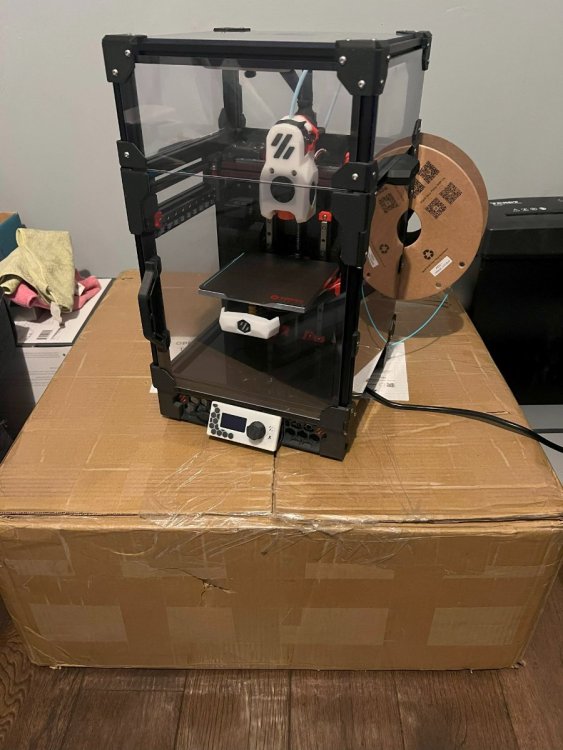
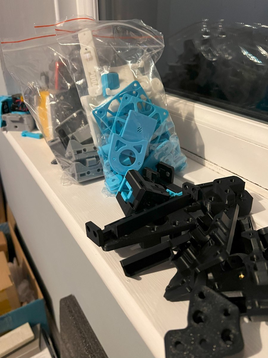
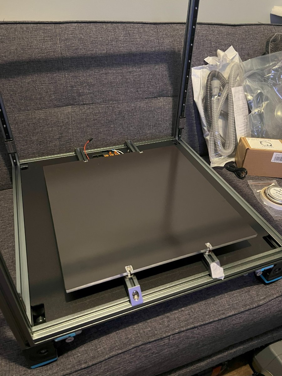
[V0.2r1 on top of shipping box]

Additional items I bought:
  • Galileo 2 kit from OneTwo3d
  • Hardware for THE FILTER
  • Hartk hardware - Pins mod and GE5C bearings
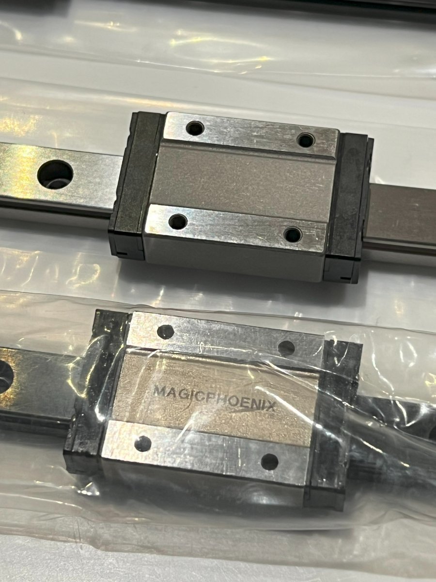
  • Stainless Steel MGN12 with medium pre-load
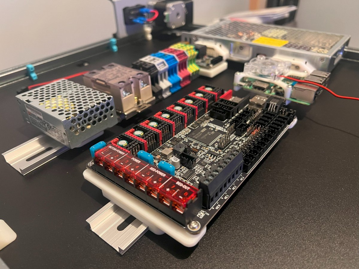
  • BTT Octopus Pro (Whilst the MPX kit contains M8Pv2+CB1, I wanted to have separate MCU and RPI 3b+ for better hardware / software support)
  • BTT PI TFT50
  • BTT KNOMI 2
  • Meanwell PSU RS-25-5 (To power the RPI)
  • CNC Metal Tap (Vitalli design)
  • Rainbow BARF LEDs
  • Klipper Expander
  • Aukey PC-LM1E USB webcam
  • Stainless Steel MGN12 linear rail with medium pre-load

 
Last edited:
The Build
 
The Parts / Colour Choice

The Voron Colour Configurator was very helpful in visualising the final build colours, as was VoronDB. Eventually I settled on SUNLU ABS Black for the gantry/chain parts, eSUN ABS+ SkyBlue for the accent parts only (not for structural) and Polymaker Polylite ABS Light Grey for internals. For external parts I used SUNLU ABS White and various mixtures of multi-filament Black/Blue/Grey.

IMG_1950.thumb.jpg.dfe3da1da78fcfa457273f2a96a13659.jpg


Magic Phoenix has a comprehensive wiki with a print and build guide. I adapted their Google spreadsheet for my own needs, meticulously tracking everything (files, colour, quantity, time etc) carefully due to the number of mods from the outset.

printed-parts-list.thumb.png.35104683be5987f1cd9f841c966e52b3.png


Setting the Voron 0.2 to work...

IMG_1399.thumb.jpg.0df77257904c6f896c953edaa1f5d769.jpg

 
Last edited:
The MPX Kit

The Magic Pheonix Kit came extremely well packaged, with different custom-cut foam layers for each section of the build.

IMG_1327.thumb.jpg.d4e8c08c858354f1b1b274a2bebe5e1c.jpg

IMG_1379.thumb.jpg.4094f253778c0c3ad2f43c5449b4afd6.jpg

IMG_1394.thumb.jpg.e791c9d9b23850d6fa90123fc3b8242f.jpg


Hardware was labelled appropriately and everything was individually bagged

IMG_1328.thumb.jpg.1cf6ef9d9678e6e9a34e3390fbd2a162.jpg

IMG_1366.thumb.jpg.55470b46ebaa03ca484ab722c22005a2.jpg


Replacements

There were not many parts of the kit which I needed to replace, given the quality of the original BOM. I optionally ordered steel Y-backers and DiscoXXL lights from MPX directly.

Whilst the MPX kit comes with a BTT M8Pv2+CB1, I wanted to have separate a MCU and RPI 3b+ for better hardware / software support, as well as power-control. I wanted to use a DSI screen which made the CB1 obsolete, and I also may consider 48V in the future which pointed me towards an Octopus Pro. The price for the Raspberry Pi 3b+ had come down and I managed to snap one up from eBay for £20!


I already had a genuine Omron SSR purchased through Mouser. However, the Omron SSR supplied by MPX looked absolutely identical and did not appear counterfeit, much to my surprise.


The MPX kit comes with black linear rails in non-stainless steel with what felt like light-preload. I replaced the MGN12 with a stainless steel rail with medium-preload


Quality

Overall the quality of the kit is superb, considering the value. It is one of the cheapest kits on the market, especially with shipping inclusive of tax to UK. All components appear genuine, genuine Phaetus hotend, extrusions perfectly cut, no additional surplus parts (Canbus and Tap included), surplus of hardware. I couldn't be happier.

MagicPhoenix have their own Discord server, as well as their on channel on the official Voron Discord. They were highly responsive to any issue, small or large. They are light-years ahead of BTT support in this regard. There was a small minor issue of missing a chain-end piece, but this was shipped via rapid courier and arrived in a few days from China, at their expense. Excellent.
 
Last edited:
The Frame

I used a couple of machinist blocks and a kitchen worktop to square my frame build. The size of the 350mm was huge compared to my v0.2. It can easily swallow it's baby brother up..

IMG_1364.thumb.jpg.a2aab8b335e1ed5162424fe4127ac76c.jpg

Z-Drives

I tested all the kit's black linear rails and found the 4x with the least preload for the Z rails. Following a 99.99% alcohol bath, I re-greased the carriers with Silverhook EP2 Lithium Grease. I found that greasing the BBs directly the most efficient method. The MPX carriers didn't come with a grease port and greasing the back through-hole gave me too much grease.

IMG_1363.thumb.jpg.834201021cd20b664b2bb67abdb2955b.jpg

Attaching the Z-drives was simple. The tensioner mechanism is a brilliant bit of Voron design - simple yet effective. I elected to use MPX's electronics layout and placed the DIN rails as per their plan.

IMG_1368.thumb.jpg.bae4d760de8732ad1fdbdb97fb3fa8df.jpg

IMG_1369.thumb.jpg.7a364c2af92bda6eb517686aed47ff77.jpg

(yes that is CPAP tubing in the background)

IMG_1367.thumb.jpg.ba2ad5ef5471ef1a2ae90ef723546c39.jpg
 
Print Bed

Again quite straight forward as per manual. I used the standard Voron method to prevent bed warp (fixed 1 point, loose 3 points). I did research kinematic mounts, but found that Voron's standard method was more than good-enough. Whilst here, I added a few mods...


Bed Wagos

The MPX heater is a 800W unit which is pre-prepared and pre-soldered with a thermal fuse. I needed 6 Wago 221-412s for:
  • Heater ~
  • Heater ~
  • Earth
  • 24V for THE FILTER (centre and sides)
  • Ground for THE FILTER (centre)
  • Ground for THE FILTER (sides)


Flex Plate Stops

Invaluable in loading spring steel sheets. I ended up using M5 socket-head screws in the end for better rigidity. They are @1mm away from the bed to allow for plate expansion.


Nozzle Scrubber

Cheap version with sawn off brushes. I might change this to Bambu Labs style silicone ones, but this works fine for the time being.


(good example of harsh light issues)


THE FILTER - Centre and 2 Sides

Having a family meant that a filter was a must. In fact, I modified the original CAD to add another 0.2 layer for the accent pattern (3 layers instead of 2). The MPX kit came with GDStime blowers for a Nevermore. The side fans are dual-BB Winsinn ones. I decided to buy cheaper as these fans are not critical.


A small Wago mount let me consolidate 24v for all 3 modules and the two side module grounds.


The cheap POGO connectors I used (10mm) were too small for the original mounts. I crated some adapters so that I could fit them perfectly snug (Printables link).

 
AB Drives / Hartk Pins Mod

I wanted to use Hartk's pins mod and originally bought a 500mm x 5mm length stainless steel rod. I found this dremel cutting mount on Printables and went to work. However, despite printing in the ABS, the cutting mount could not tolerate the heat generated by the cutting friction. Even more frustratingly, having taken 30 minutes to cut one pin, the pin was too tight to fit. I then found out that commercial "pins kits" were 4.9 - 4.95mm so I ordered a kit. Lesson learnt, cutting stainless steel rods with a Dremel is no fun at all. Saving £5 was not worth the time and effort.

IMG_1370.thumb.jpg.fadd821b440da1b0048c7ae6af91d04b.jpg

IMG_1397.thumb.jpg.9cfb40c8350dcb0596a8fff966f69189.jpg

Y-Gantry Backers

The MPX kit was ordered with optional Y-gantry backers (steel in black) for an extra $10. Bargain. I didn't feel an obvious need for an X-backer given the vertical orientation of the X rail.

IMG_1416.thumb.jpg.ba636cc0d1946504f23bb9fedc0e0693.jpg

Hartk GE5C Mod

I used the slimmer mount of the Hartk GE5C Mod. Whilst the bearings were expensive, I did not want to run any risk of QGL issues.

IMG_1442.thumb.jpg.5c9896681dacaa94e4a6d0dd5f4e2f2d.jpg
 
The Gantry

To avoid issues with part strength, I used Beefy Z-Idlers (part of the Beefy Front Idlers pack). I had to order some more pins and at that point I realised how much of a hassle it would have been to self-source everything (respect to you all!).

IMG_1462.thumb.jpg.f0da237c81e98662ec0692cdec06dd81.jpg

As mentioned, Beefy Front Idlers (BFI) was deployed for the AB idlers. Instead of the standard faceplate, I used MapleLeafMaker's RGBFI with the original intention of running Neopixels in there. Whilst I think it would be just about possible to run 3-4x lengths of thin wiring in the gantry and Z-chain, I felt it would be too much of a tight fit near the idler bearing. Perhaps a project for a (very) lazy Sunday.

IMG_1461.thumb.jpg.b307e78b26dff53fa896069b403495b7.jpg

I used simple zip-ties to "hang" the gantry, findings the printed Z-lockers a bit too flimsy.

IMG_1445.thumb.jpg.49a98276a860e4378fabd90e004e266c.jpg

I replaced the MPX MGN12 black steel rail with a stainless steel one with medium-preload. YOUMETONG was recommended quite a lot in the Voron Discord as the best balance between cost/quality.

IMG_1441.thumb.jpg.3d665825fa7b1c060daf5e710d55c76b.jpg

The Gantry mount on to the GE5C mod perfectly and I went through the usual squaring and de-racking guides. I eventually replaced the washes with these aluminium spacers (8mm diameter, 5mm hole, 3mm length).

IMG_1464.thumb.jpg.5a5e09bacef384eee7c24762ab642170.jpg IMG_1463.thumb.jpg.03a1cb9f7f0dabfea863d0d2c14d1254.jpg

With most of the gantry installed, I relocated the Z chain to below the gantry. Aesthetically this worked better for me, removing the awkward vertical Z-chain for a neater solution. The original Z-chain supplied in the MPC kit was too big for this purpose, with too large a bend-radius and too wide a channel. Instead I ordered a small bend-radius chain (R18, 10x11 open - matching the original XY chain spec).

IMG_1793.thumb.jpg.0ac345bd735b7f1528cda87b9c020439.jpg

I then placed my camera and a thermistor on the rear gantry, running through the Z-chain.

IMG_1954.thumb.jpg.8d94a40460b434082e9104e929531718.jpg
 
Voron TAP

For probing, the MPX kit comes with all the necessary hardware for a Voron TAP as standard. I initially printed all the parts out in ABS but elected to treated myself to a CNC part. I use 2x Magnets and 2x Screws for the configuration of the TAP, finding it a good balance between rigidity and movement. The CNC part really made the whole carriage super sturdy, with hardly any toolhead flex.

IMG_1457.thumb.jpg.73ee2d1a3a449582991d31eb56b27704.jpg

IMG_1459.thumb.jpg.86c35512c0c28f03c3b98bc497eb6309.jpg

I noticed when using the CNC TAP, it hardly takes any vertical movement to trigger the optical switch. About 0.5-1.0mm before triggering. I'm not sure whether this is a good or a bad thing.

After using the TAP for a while, my conclusion is that it is very accurate. I'm getting reasonably good standard deviation on my PROBE_ACCURACY tests. However, meshing and QGL is slow. I use adaptive-meshing in my PRINT_START so I may consider swapping everything over to an Eddy sensor in the future.
 
Toolhead

Whilst I finally settled on a DragonBurner in my v0.2, I elected for a standard StealthBurner for this build. 1) I quite like the aesthetic, 2) I wanted to run KNOMI2 at the toolhead, 3) I will print mainly in ABS so am not too fussed about having jet-engine part cooling and 4) I have all the hardware ready to switch to CPAP using this muffler by Mammoth-FDM if I ever decide to print more PLA.

For the hotend, I ordered the Phaetus Rapido 2 via MPX directly as an upgrade option. In to this went a 0.4mm CHT nozzle.

IMG_1395.thumb.jpg.e350be41e53de8452c1e32d5a3e4697f.jpg

In a surprising touch of quality, the MPX kit comes with dual ball bearing GDSTime fans throughout.

IMG_1407.thumb.jpg.4a2783211008e867052968cf63d9e430.jpg

My extruder of choice was the Galileo 2, a drop-in replacement in the StealthBurner. I originally printed beta-release parts, later rebuilding with the final release-candidate STL/CAD parts.

IMG_1321.thumb.jpg.909f6f0e0a0582e59fa2864c8f6fd40c.jpg

IMG_1323.thumb.jpg.e171f6d9dd4aa99f08faba57f6fdcdf6.jpg

The MPX kit also comes with BTT's SB2209 can board as standard. The squeeze was a bit tight and I eventually had to buy pre-crimped connectors to make the thermistor connection a bit more reliable. Trying to crimp 1.25 connectors was possibly the most traumatic thing of the toolhead build so I gave in! Thankfully the MPX kit included everything else pre-crimped (X-endstop and OptoTap PCB).

IMG_1469.thumb.jpg.6f0f235bf6bbe51c8a291ec7181567cc.jpg

I added a 27mm RPi fan to the cover using this great mod. Power supply is 5V through the selectable PWM fan port of the SB2209 breakout board.

IMG_1467.thumb.jpg.118f0e852547f66481f341c455180413.jpg

I settled on this fancier front plate and used Rainbow BARF for the logo light running the Klipper LED effects plugin. The KNOMI2 recently had a new mount published which seemed a bit more rigid. However, it was a total pain to fit and rubbed against the part-cooling fan. I had to increase the "inner diameter" of the mount by manually filing it down (CAD published but too cumbersome to edit for me).

IMG_1970.thumb.jpg.b215be244c8c1c063d38901f0627a22d.jpgIMG_1971.thumb.jpg.cfc01f7cd04895f37df7dac38f1875ec.jpg

Job done.
 
CANBUS

The MPX kit comes with CAN toolhead boards (BTT SB2209) and hardware (cable reliefs, cable braid, steel wire). The default build option from MPX is to connect the toolhead to the rear AB mount via a steel wire. After all, no one likes it floppy. For this, they have their own printed part, with supplied custom PCB for the y-endstop and an onboard SMD thermistor. I did consider this but doing a dry-fit with the gantry at maximum Z-height, I really did not fancy the umbilical rubbing the top panel. I also disliked the aesthetic of the wiring.

656b78cae6433.thumb.jpg.3ceda265b919cd46e14d4bec524a0a57.jpg

Instead, I elected to run the CAN cable via the exhaust with the filament tube, resulting in a cleaner aesthetic and better routing in my opinion...

IMG_1800.thumb.jpg.5be5039a12297d2a57a61591d71187b9.jpg

Versus...

IMG_1924.thumb.jpg.717ef5eb8ce368a9545135eafbba568c.jpg

IMG_1971.thumb.jpg.19c61d17fc31e065145046327d32019b.jpg

Internally I used these parametric clips to route the filament and CANBUS cables together, with the CANBUS cable running through a braid (purely for bling).

IMG_1967.thumb.jpg.97e7eb6c2b8de22e1c70bf2bcc11e646.jpg

For the back panel, I combined VEFACH with this exhaust remixed with an additional M12 mount for a CAN cable. This was run through this exhaust fan grill (which I modified to remove the thermistor port).

IMG_1928.thumb.jpg.b84fcc10e5e0db4e1bd218c03056f023.jpg

IMG_1942.thumb.jpg.1124981130c2628783149d71585cfd39.jpg

CANBUS Electronics

The BTT can cable was routed as shown. I modified these clips so that the panel can still be removed with clips in situ. The clips also route the filament sensor and the VEFACH mount cables.

IMG_1941.thumb.jpg.2b613ee5859372817ee710f60617f79a.jpg

This fed into a 4x2 Wago mount near the rear of the electronics bay, through this modified centre skirt, supplying 24v, GND, CAN-H and CAN-L.

IMG_1484.thumb.jpg.4dca5f84d08b74a9320b4c43e1bc474f.jpg

This in turn was run directly to the Octopus Pro RJ11 CAN port in a custom twisted-pair loom (dark blue braid). This type of adapter was used.

IMG_1940.thumb.jpg.621d39df6881cf5f5e101265cee96777.jpg

The whole system is setup with Katapult and an automated update script for one-command flashing (my custom update-all.sh bash script)...

Code:
# --------------------------
# Full Update Script (MCU and Toolhead only)
#
# sh update-all.sh
# --------------------------
echo -e "\e[1;31m --- Stopping and Updating Klipper --- \e[0m"
sudo service klipper stop
cd ~/klipper
git pull

echo -e "\e[1;33m --- Building Octopus Klipper Firmware --- \e[0m"
make clean KCONFIG_CONFIG=config.octopus
make menuconfig KCONFIG_CONFIG=config.octopus
make KCONFIG_CONFIG=config.octopus

read -p "Octopus firmware built, please check above for any errors. Press [Enter] to continue flashing, or [Ctrl+C] to abort"

echo -e "\e[1;31m --- Flashing Octopus Firmware --- \e[0m"
python3 ~/katapult/scripts/flash_can.py -u 3dbe73805ca0
python3 ~/katapult/scripts/flash_can.py -d /dev/serial/by-id/usb-katapult_stm32f429xx_2A004E000551313133383438-if00

read -p "Octopus firmware flashed, please check above for any errors. Press [Enter] to continue, or [Ctrl+C] to abort"

echo -e "\e[1;33m --- Building Toolhead Klipper Firmware --- \e[0m"
make clean KCONFIG_CONFIG=config.toolhead
make menuconfig KCONFIG_CONFIG=config.toolhead
make KCONFIG_CONFIG=config.toolhead

read -p "Toolhead (SB2209) firmware built. Please check for errors. Press [Enter] to continue flashing or [CTRL+C] to abort"

echo -e "\e[1;31m --- Flashing Toolhead Firmware --- \e[0m"
python3 ~/katapult/scripts/flash_can.py -u b6819f9796d7

read -p "Toolhead firmware flashed, please check above for any errors. Press [Enter] to continue, or [Ctrl+C] to abort"

echo -e "\e[1;32m --- Restarting Klipper --- \e[0m"
sudo service klipper start
 
Last edited:
VEFACH

I really wished to keep the exhaust filter to run VEFACH. Unfortunately the MPX kit closes off the exhaust filter in their recommended print list / build. Thankfully I had a 12V 60mm high-RPM Delta fan from a couple of decades-old PC build. It sounds like an Airbus A380 taking off at 100% speed!

The VEFACH was easy to print and thankfully worked fine with my modified CAN-cable housing.

IMG_1927.thumb.jpg.8c6abf1e394c084e3bb4caa2e8368f5c.jpg

IMG_1928.thumb.jpg.aae28b6a26805d3f5bde563d5dda68c8.jpg

I customised a VEFACH config...

Code:
[gcode_macro _VEFACH]
variable_fan: 'VEFACH_Fan' # Name of fan
variable_fast: 0.4           # Default Fan speed fast
variable_slow: 0.2           # Default Fan speed slow
variable_timer: 600        # Default timer in seconds
gcode:

[gcode_macro VEFACH_ON]
description: Turn on the VEFACH fan.
gcode:
{% set vefachcfg = printer["gcode_macro _VEFACH"] %}
{% set SPEED = params.SPEED|default(vefachcfg.fast)|float %}

M118 Turning VEFACH ON ({SPEED*100}%)
SET_FAN_SPEED FAN={vefachcfg.fan} SPEED={SPEED}

[gcode_macro VEFACH_OFF]
description: Turn off the VEFACH fan.
gcode:
{% set FAN = printer["gcode_macro _VEFACH"].fan %}

M118 Turning VEFACH OFF
SET_FAN_SPEED FAN={FAN} SPEED=0

[gcode_macro START_VEFACH_TIMER]
gcode:
{% set vefachcfg = printer["gcode_macro _VEFACH"] %}
{% set TIME = params.TIME|default(vefachcfg.timer)|int %}

M118 Starting VEFACH Timer ({TIME}seconds)
UPDATE_DELAYED_GCODE ID=STOP_VEFACH DURATION={TIME}

[delayed_gcode STOP_VEFACH]
gcode:
VEFACH_OFF

[gcode_macro CANCEL_VEFACH_TIMER]
gcode:
M118 Cancelling VEFACH Timer
UPDATE_DELAYED_GCODE ID=STOP_VEFACH DURATION=0

with this in PRINT_END
Code:
# Turn on VEFACH if ABS bed
      {% if printer.heater_bed.target >= THRESHOLD %}            ; Continue only if target temp greater than threshold.
VEFACH_ON
START_VEFACH_TIMER
{% endif %}
THRESHOLD being called upon from a pre-set high bed temperature variable (i.e. ABS bed temp of 90C+).

This sets the VEFACH off at the end of the print with a delayed gcode to stop it after 10 minutes.

Filament Path

The pathing of the filament was through a BTT SFS v2.0 (later found to be quite an unreliable device, especially the 'smart encoder' part).

IMG_1953.thumb.jpg.e26c7925dbcdbc82f44ffa55822da410.jpg

IMG_1963.thumb.jpg.187d429b60e972728f0126885d22315c.jpg

IMG_1964.thumb.jpg.e3ffd98ad40cec07e81fa9b297944725.jpg
 
Top