VORON Design
You are using an out of date browser. It may not display this or other websites correctly.
You should upgrade or use an alternative browser.
You should upgrade or use an alternative browser.
TAP Sensor Wiring on an SB2040
- Thread starter Takuya
- Start date
Smart_ Ostrich_V2.3824
Member
does this wiring work with both OctoTAP 5v and 24v?
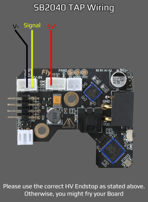
The TAP sensors have a 5V signal, the MCU on the sb2040 can only handle 3.3V signal thus damaging it.Just out of curiosity, why not use the v- and signal pins of the endstop? Why split it between HV endstop and the endstop? The endstop has 5v, gnd, and signal?
The HV endstop has a diode between the mcu and the port, protecting it from 5V.
normal endstop doesnt.
garrettwp
Active member
Thank you for the clarification. That makes sense!The TAP sensors have a 5V signal, the MCU on the sb2040 can only handle 3.3V signal thus damaging it.
The HV endstop has a diode between the mcu and the port, protecting it from 5V.
normal endstop doesnt.
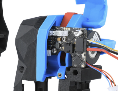
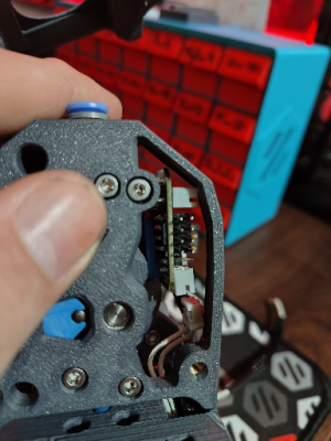
You plug it in beforehand then you Insert the pcb and tighten the screws. Its a little tight
asalfinger
New member
Glad I found this thread before cooking my board, doesn't seem to be much info out there about using this CAN board,
I can see the LED on the TAP board lighting up but the probe never triggers I have double and triple-checked my wiring but can't seem to work it out, I suspect it is either an issue with the SB2040 or just simply a bad config on my part
Could anyone share a working config for this toolhead board?
My Probe Config is below:
[probe]
pin: sb2040:gpio25
x_offset: 0
y_offset: 0
z_offset: 0
speed: 10.0
samples: 3
samples_result: median
sample_retract_dist: 3.0
samples_tolerance: 0.006
samples_tolerance_retries: 3
activate_gcode:
{% set PROBE_TEMP = 150 %}
{% set MAX_TEMP = PROBE_TEMP + 5 %}
{% set ACTUAL_TEMP = printer.extruder.temperature %}
{% set TARGET_TEMP = printer.extruder.target %}
{% if TARGET_TEMP > PROBE_TEMP %}
{ action_respond_info('Extruder temperature target of %.1fC is too high, lowering to %.1fC' % (TARGET_TEMP, PROBE_TEMP)) }
M109 S{ PROBE_TEMP }
{% else %}
# Temperature target is already low enough, but nozzle may still be too hot.
{% if ACTUAL_TEMP > MAX_TEMP %}
{ action_respond_info('Extruder temperature %.1fC is still too high, waiting until below %.1fC' % (ACTUAL_TEMP, MAX_TEMP)) }
TEMPERATURE_WAIT SENSOR=extruder MAXIMUM={ MAX_TEMP }
{% endif %}
{% endif %}
staticanime
Member
yeah. its the same for me. it does fit.Do you by any chance have a picture of *how* tight yours is, mines flush with the outer Clockwork body, I really don't think there's enough room for cabling+connector?
View attachment 1258
Im a function over looks guy so i just cut the side part of the CW2 housing off
Měl jsem stejný problém jako ty. Připojil jsem se na pin s GPIO 28 s 5 volty a funguje. Tohle nefungovalo na GPIO29 a nevím jestli je problém s 24V nebo s GPIOxxJsem rád, že jsem našel toto vlákno před vařením své desky, nezdá se, že by tam bylo mnoho informací o použití této desky CAN,
Vidím, že se LED na desce TAP rozsvěcuje, ale sonda se nikdy nespustí Dvakrát a třikrát jsem zkontroloval kabeláž, ale nezdá se mi, že bych to mohl vyřešit, mám podezření, že je to buď problém s SB2040, nebo je to prostě špatné konfigurace z mé strany
Mohl by někdo sdílet funkční konfiguraci této desky nástrojů?
Moje konfigurace sondy je níže:
I had the same problem as you. i connected to pin with GPIO 28 with 5 Volts and it works. This didn't work on GPIO29 and I don't know if it's a problem with 24 volts or with GPIOxxMěl jsem stejný problém jako ty. Připojil jsem se na pin s GPIO 28 s 5 volty a funguje. Tohle nefungovalo na GPIO29 a nevím jestli je problém s 24V nebo s GPIOxx
Dont connect the TAP sensor wire to GPIO 28 or 29.I had the same problem as you. i connected to pin with GPIO 28 with 5 Volts and it works. This didn't work on GPIO29 and I don't know if it's a problem with 24 volts or with GPIOxx
Only 25 as that has a diode protecting the rp2040.
Gpio 28 and 29 dont have that so it will fry your rp2040 chip on the sb2040
HowdyGlad I found this thread before cooking my board, doesn't seem to be much info out there about using this CAN board,
I can see the LED on the TAP board lighting up but the probe never triggers I have double and triple-checked my wiring but can't seem to work it out, I suspect it is either an issue with the SB2040 or just simply a bad config on my part
Could anyone share a working config for this toolhead board?
My Probe Config is below:
where is each wire going? Like the picture in the beginning of the thread?
gpio25 is correct so it should work this way.
You said that the led is lit. Does that change when the probe activates?
Dont connect the TAP sensor wire to GPIO 28 or 29.
Only 25 as that has a diode protecting the rp2040.
Gpio 28 and 29 dont have that so it will fry your rp2040 chip on the sb2040
Unfortunately GPIO25 doesn't work for me. I've been using GPIO28 for 3 days now and everything is working so far. If there is protection on GPIO25 I would like to install it. Currently it is via one JST connector (5V, GND, GPIO28)
Doesnt work as in?Unfortunately GPIO25 doesn't work for me. I've been using GPIO28 for 3 days now and everything is working so far. If there is protection on GPIO25 I would like to install it. Currently it is via one JST connector (5V, GND, GPIO28)
Just doesnt trigger?
There shouldnt be a difference in terms of usage.
Doesnt work as in?
Just doesnt trigger?
There shouldnt be a difference in terms of usage.
if I connect it to the JST with GPIO25, the light on the optical sensor lights up and if I press the head it turns off (it induces the functionality of the optical sensor) but the printer does not stop and it moves downwards in the Z axis. If I do the same on the JST connector with GPIO28, everything works the same, but the printer recognizes the signal from the GPIO. the GPIO port probably doesn't work or I don't know ;-)
but you did change the pin to GPIO25 right?if I connect it to the JST with GPIO25, the light on the optical sensor lights up and if I press the head it turns off (it induces the functionality of the optical sensor) but the printer does not stop and it moves downwards in the Z axis. If I do the same on the JST connector with GPIO28, everything works the same, but the printer recognizes the signal from the GPIO. the GPIO port probably doesn't work or I don't know ;-)
I’m quite certain this information is outdated. The sensors specified for the tap will only ever be pulled low or floating, the pin will never see 5v. Gpio28 should be fine
Edit: see https://forum.vorondesign.com/threads/concerning-wired-sensors-for-tap.151/
Edit: see https://forum.vorondesign.com/threads/concerning-wired-sensors-for-tap.151/
Last edited:
Similar threads
- Replies
- 6
- Views
- 3K


