
- Printer Model
- Voron Trident mod
- Extruder Type
- Other
- Cooling Type
- Other
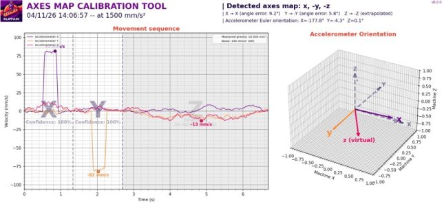
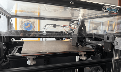
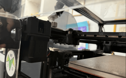
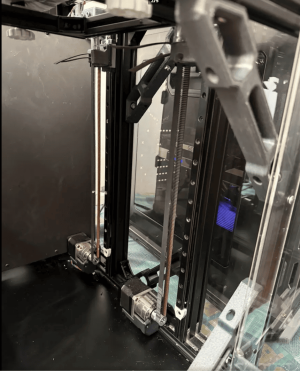
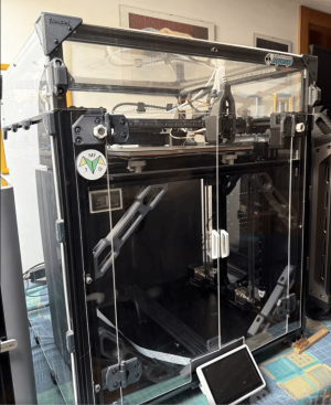
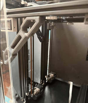
Good morning, I'd like to ask you for some clarification on the vibration results obtained with Klipper. Unfortunately, my setup is a hybrid configuration, meaning it's not exactly a trident; the platter moves in the z-axis, while the xy core is fixed. I have four reduced motors for each corner of the platter for autotraction, and four motors for the xy core, one for each corner. Here's the complete setup.
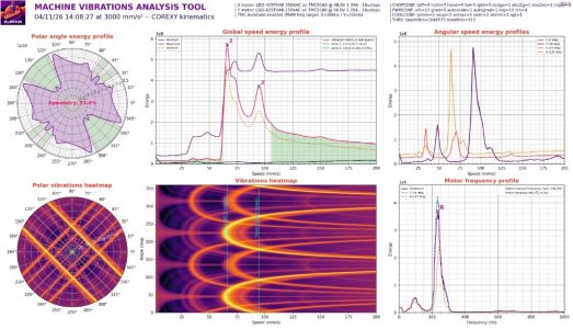
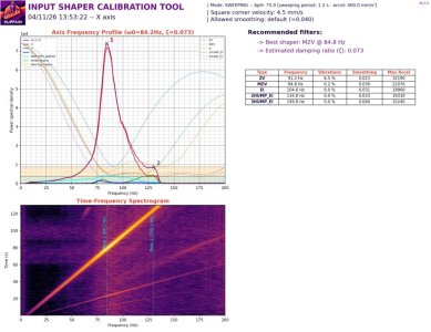
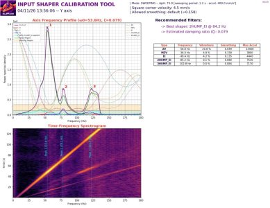
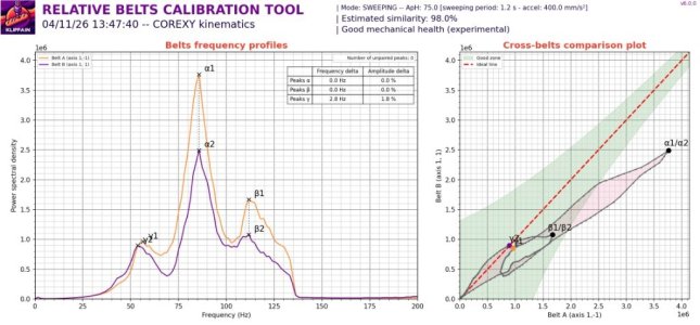
The problem is that I have a significant misalignment, or at least that's what I think, between x and y. I've attached the images. This results in a symmetry of 53%. I was hoping it would be much higher, and it also results in low accelerations for the setup. In summary, y has a critical frequency around 60 Hz, while x is around 90 Hz. I thought they were closer. Still with lower y, but not by much.
The belts are tightened and measured with a special tool. The structure is solid, completely made of aluminum. The machine is built with respect for the angles... Could someone please give me some advice on how to resolve this situation? Thank you very much.
Voron Configuration
- Z-Axis: 4 independent motors with planetary gearboxes for the bed, mounted on four 12mm linear rails. This allows for quad-corner auto-leveling.
- XY Axis (CoreXY AWD): 4 motors (paired 2x2) on 12mm linear rails (LDO motors) with 300 mm travel.
- X-Axis: 12mm linear rail with 300mm travel.
- Hotend: Rapido Plus UHF (Ultra High Flow) with a hardened steel nozzle.
- Probing: Cartographer 3D with a CNC milled aluminum mount
- Toolhead Electronics: EBB 42 v1.2 CAN bus with built-in ADXL vibration sensor.
- Host: Raspberry Pi 4
- Mainboard: BigTreeTech Super 8 Pro
- Stepper Drivers: External Mellow TMC 5160 for each CoreXY motor.
- Power Supply: Dual PSU setup — 48V for the steppers, 24V for sensors and heaters.
- Cooling: CPAP system for high-speed part cooling.
- Filament Sensor: BTT SFS v2.0 for filament and flow monitoring.
- Frame: Full aluminum structure.
- X-Beam: CNC milled truss structure (milled from solid aluminum).
- Extruder: Sherpa Micro.
- Enclosure: Fully enclosed for technical materials.
- Automation: Shelly relay for automatic shutdown after printing.
- Display: 7-inch front touch monitor for printer control.
The problem is that I have a significant misalignment, or at least that's what I think, between x and y. I've attached the images. This results in a symmetry of 53%. I was hoping it would be much higher, and it also results in low accelerations for the setup. In summary, y has a critical frequency around 60 Hz, while x is around 90 Hz. I thought they were closer. Still with lower y, but not by much.
The belts are tightened and measured with a special tool. The structure is solid, completely made of aluminum. The machine is built with respect for the angles... Could someone please give me some advice on how to resolve this situation? Thank you very much.
Attachments
-
 14a3ae3d-3a10-4924-b8b4-dea70f2ed5cd.jpeg150.6 KB · Views: 1
 -
 06876878-6de7-4360-a5f9-717a74eee315.jpeg125.3 KB · Views: 0
 -
 8e98ce54-baea-411e-8996-90c34c31c11f.jpeg128.5 KB · Views: 0
 -
 0b6dd819-917c-420d-9eff-d4a013ced6d0.jpeg107.6 KB · Views: 0
 -
 334ec48c-474d-4b1f-bfba-f1570aed941d.jpeg97.9 KB · Views: 0
 -
 1.png581 KB · Views: 0
 -
 2.png501.4 KB · Views: 1
 -
 3.png343 KB · Views: 0
 -
 4.png345.5 KB · Views: 0
 -
 5.png307.9 KB · Views: 0