What's new
VORON Design

Register a free account today to become a member! Once signed in, you'll be able to participate on this site by adding your own topics and posts, as well as connect with other members!

Extrusion or bed level? Trident 300 build

evan

Member
Hello all. I have a LDO Trident 300 which I have built but have never been happy with how it prints the first layer. If I print a small 30mm x 30mm first layer box at the centre of the bed, the spacing of the lines is uneven. Usually one half of the square has gaps while the second is close to perfect. My first thought was uneven extrusion so I disassembled the extruder and found the gears had been rubbing on the printed parts. I decided to upgrade to cw2 so purchased a new pancake motor and printed the new parts. I now have that up and running but am having the same issues. I then decided the inductive probe may be the issue so printed and installed KlickyNG. No luck, same issue. I have tried variable bed mesh also without any luck.

I guess I am looking for another set of eyes so to speak. I'm at a loss as to where to go from here? New extruder maybe? Anyway thoughts anybody? Cheers!
 

NoGuru

Well-known member
Really you need to measure to see what is out of square or flatness. A machine shop could do this or you can replace the extrusion or rails. Maybe you can shim the bed under the build surface with some tape?
 

Hot Toddy

Member
Hello all. I have a LDO Trident 300 which I have built but have never been happy with how it prints the first layer. If I print a small 30mm x 30mm first layer box at the centre of the bed, the spacing of the lines is uneven. Usually one half of the square has gaps while the second is close to perfect. My first thought was uneven extrusion so I disassembled the extruder and found the gears had been rubbing on the printed parts. I decided to upgrade to cw2 so purchased a new pancake motor and printed the new parts. I now have that up and running but am having the same issues. I then decided the inductive probe may be the issue so printed and installed KlickyNG. No luck, same issue. I have tried variable bed mesh also without any luck.

I guess I am looking for another set of eyes so to speak. I'm at a loss as to where to go from here? New extruder maybe? Anyway thoughts anybody? Cheers!
Did you set your “rotation distance” correctly for your Z steppers in your printer.cfg? I had similar problems with my Trident until I realised I’d set my “rotation distance” to 8 instead of 4. (Check the specs of you Z stepper motors that should have come with your kit.) Once I resolved this everything started to print as expected.
 

evan

Member
Double checked. Mine are TR8x4, 1.8 deg steppers. They are LD0-42STH40-1684CL350ET(VRN) steppers which if I am correct should be;

rotation_distance: 4
full_steps_per_rotation: 200

Thanks Hot Toddy.
 

evan

Member
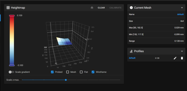
And my Adaptive Bed mesh with Klicky probe. Screenshot 2023-05-24 101208.png
Really you need to measure to see what is out of square or flatness. A machine shop could do this or you can replace the extrusion or rails. Maybe you can shim the bed under the build surface with some tape?
I did a bad job of explaining my thoughts above - what I meant was the hotend and/or extruder are extruding inconsistently. I am not sure if that is how you read it or not. However, if my aluminum extrusion or rails are warped what would be the best way to correct those? I have seen titanium backers and carbon extrusions online.... would you know if they help much? Currently I have the LDO kit stainless steel backers in all of my rail extrusions. Thanks!
 

7milesup

Active member
Frankly, I doubt that the extrusions or rails are warped unless the quality was horrendous to begin with. I would suspect that the build plate may be more of an issue than anything else. So many of these vendors talk about cast plates but in reality, I think they are just plate aluminum that is machined "flat." By looking at your bed mesh, you possibly try a very small shim on the right front corner to see what happens.
 

evan

Member
Frankly, I doubt that the extrusions or rails are warped unless the quality was horrendous to begin with. I would suspect that the build plate may be more of an issue than anything else. So many of these vendors talk about cast plates but in reality, I think they are just plate aluminum that is machined "flat." By looking at your bed mesh, you possibly try a very small shim on the right front corner to see what happens.
Thanks for the reply! I should have posted a full bed mesh but was trying something with a smaller print. Sounds like a good idea though. Certainly worth trying before rebuilding the x & y or spending too much on parts. Cheers!
 

claudermilk

Well-known member
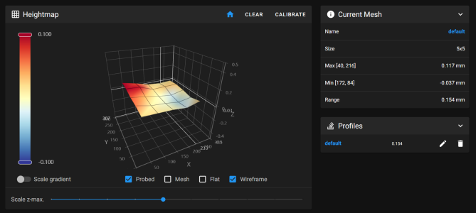
Do a full bed mesh to see what the whole bed looks like. From that small sample, You might have a crooked Y extrusion. Check the position of the ends of your Y extrusions.
 

evan

Member
Do a full bed mesh to see what the whole bed looks like. From that small sample, You might have a crooked Y extrusion. Check the position of the ends of your Y extrusions.
Hi claudermilk. Yes, the full bed mesh reveals more, which I don't think can be fixed by shimming. Sorry, I forgot to save the image so can't post that. I think my best option is to rebuild the x and y gantry. I'd like to add the pins mod and maybe the rama idlers while I'm at it. What do you mean by checking the ends of the Y extrusions? - do you mean for level?
 

claudermilk

Well-known member
I don't think you need to rebuild all that. It looks like the left rear Y extrusion is a bit low (someone correct me if I'm wrong). Loosen that and get it to exactly the same distance from the top or bottom of the main frame and re tighten. I ran into the same issue with my initial build. I had to adjust my rear right by 0.1mm and after that my mesh came out much more even.

Basically, check the measurement on each end of both Y extrusions and make sure they match as close as you can get. Some time spent here will pay off when you get back to running a mesh.
 

evan

Member
I don't think you need to rebuild all that. It looks like the left rear Y extrusion is a bit low (someone correct me if I'm wrong). Loosen that and get it to exactly the same distance from the top or bottom of the main frame and re tighten. I ran into the same issue with my initial build. I had to adjust my rear right by 0.1mm and after that my mesh came out much more even.

Basically, check the measurement on each end of both Y extrusions and make sure they match as close as you can get. Some time spent here will pay off when you get back to running a mesh.
Ok, sounds like a better option. I thought my ocd had kicked in over getting them exact when first building but it appears not. Cheers!
 

Le0n

Well-known member
Trusted Advisor
Voron Owner
When I adjust my gantry corners, my goal is to set them so that they aren't the highest or lowest spots in my mesh. In your case, like claudermilk says, the rear left is sitting a bit too low, so I would loosen that screw and raise it .1-.2mm or so, retighten, re-Z-tilt (important!), and take a new mesh. Repeat until the corners are satisfactory. It's helpful to put a piece of tape to mark the starting point as a reference so you know how much you are adjusting.
 

evan

Member
Thank you LeOn. Really appreciate you sharing that. I plan on working on my trident this weekend. Will keep you all posted on how it goes.
 

evan

Member
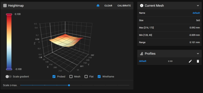
Just wanted to say thanks to all for the suggestions to the problem I have been experiencing with my new Trident. I managed to achieve better results to the bed mesh on my printer. Initial test prints are much better to what I was getting previously. My only worry is the fact that I had to adjust the back left so much. Does that suggest there is something else out in the gantry somewhere?

Also - should I continue to tweak based on my results? :unsure:
 

Attachments

  • Screenshot 2023-05-29 100955.png
    Screenshot 2023-05-29 100955.png
    120.5 KB · Views: 4

evan

Member
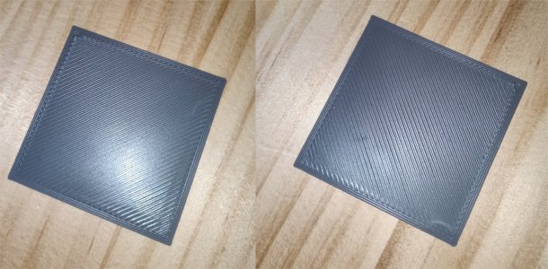
Unfortunately I spoke too soon. While overall the results look much better than before, the bottom layer / first layer is still inconsistent depending on where parts are placed. There's also an uneven or inconsistent extrusion issue at play I think, which isn't helping.

Silly question coming - but I was under the impression the bed mesh calibration routine would help in compensating for high and low area's of the bed?
 
Last edited:

Le0n

Well-known member
Trusted Advisor
Voron Owner
Unfortunately I spoke too soon. While overall the results look much better than before, the bottom layer / first layer is still inconsistent depending on where parts are placed. There's also an uneven or inconsistent extrusion issue at play I think, which isn't helping.

Silly question coming - but I was under the impression the bed mesh calibration routine would help in compensating for high and low area's of the bed?

Hm… A 0.101mm range on a 250mm bed is not terrible and should definitely be corrected by the mesh. Can you share a photo of first layer inconsistencies? Also, paste your [PRINT_START] macro or share your config file so we can make sure the mesh is active and not somehow being removed prior to printing.
 
Top