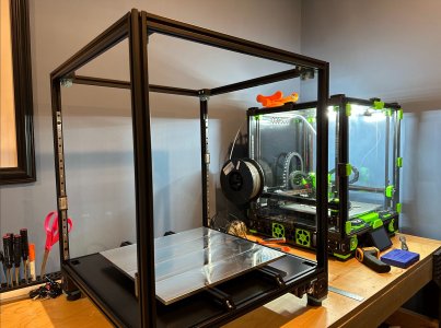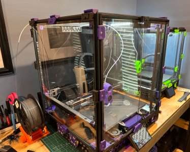
Hi everyone. Documenting my 2nd Voron 2.4R2 build and figured I would get a thread going before the build starts to see if anyone has a better plan than what I have going.
Learned a lot from my 300mm build, which was started as a stock kit from voronkits.com. The kit arrived in early December and I completed it (slowly) by late January - have to love holidays and family time! The only thing I added to that build was a SB 2-piece board, LDO toolhead cable, snap latches, bed fans/nevermore, and lighting. I have ~500hrs on it now and recently upgraded the build plate, but other than that all the functional parts were from the formbot kit. All the electronics/fans/motors/etc. were the base kit.
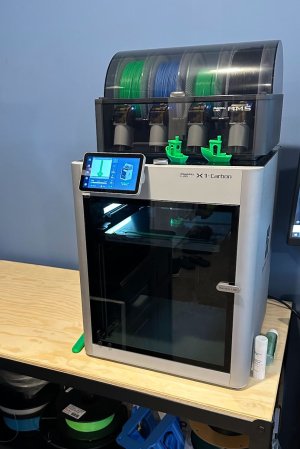
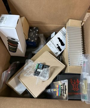
Here is a list of components I have already sourced and acquired, and most of the printing has been done. I have a few things to sort, like which Canbus setup to use, and the associated prints for the mounting/cooling on the toolhead, but the parts are already here so the prints are the last step in the chain, which is under my control at this point. I have been teetering on using my LGX-Lite w/ Stealthburner, but kind of want to leave that for my Tri-zero build that is now waiting on me to complete this one. I expect this build will carry me into the summer and stave off the urge to pick up a X1C ... anyway, here is my build list:
Vendor list:
voronkits.com
fabreeko.com
west3d.com
heatsinkonline.com
amazon.com
aliexpress.com
dfh.fm
350mm Formbot Kit from voronkits.com
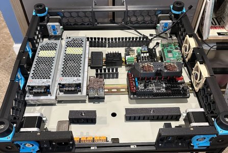
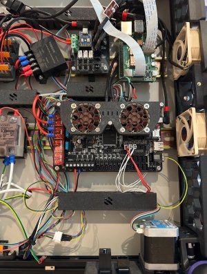
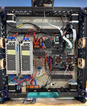
Electronics compartment:
BTT Octopus Pro (2x TMC5160 and 4x 2209)
BTT PiTFT50
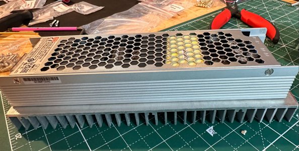
MW UHP-350-24
MW UHP-350-48
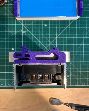
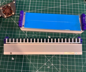
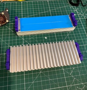
Custom Heatsinks for the UHP supplies to help get more than the derated ~250w and generally stay cooler
TinyFan for electronics bay fans
OctoGlasses mod/fans for HV steppers
Noctua 6025 fans for electronics bay and Noctua 4010 for glasses/Pi
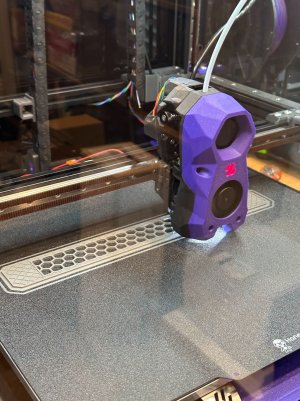
Toolhead:
GDSTime 5015 for Stealthburner
EBB36 Canbus / U2C (Not decided on Can setup quite yet - also have a SB2040 originally planned for my 300 I can use)
TAP kit from LDO (Have a HoneyBadger 50mm rail if I don't like the included LDO) / R8 Tap printed out
Rapido HF PT1000 (Also have a 2nd Revo I can use and a .6 Obxidian laying around as the .4 Obx is in the 300mm)
Bondtech BMG Integrated Drive Gear Assembly (bearings from Amazon) for CW2
LDO-36STH20-1004AHG for CW2 stepper
Rainbow Barf
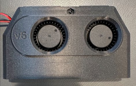
Wire shroud w/ 3010 fan for Can stepper cooling
Gantry:
LDO 2STH48-2804AH Super Speedy / Super Power High Temp for A/B motors
Titanium Backers
HoneyBadger MGN9H rails for Y
HoneyBadger MGN12H rail for X
Pin Mods for A/B and Rama Front Idlers
Igus GE5C Bearings for Z
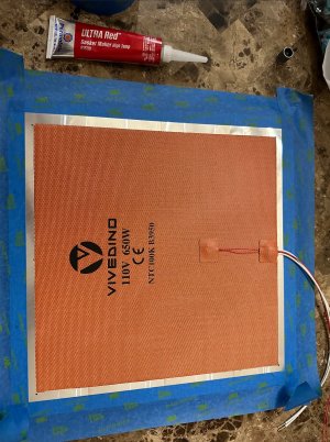
Bed:
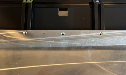
Kinematics Mount
Bed Wagos
HoneyBadger single Sided black Textured PEI
Ellis Bed Fans (Amazon 5015's for bedfans)
Nevermore w/ GDSTime 5015's
Frame:
3x Daylight XXL strips
Snap Latches
OV5640-style USB camera for overhead / Pi Cam for build-plate level
Parts:
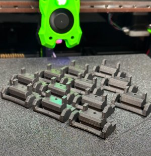
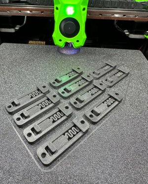
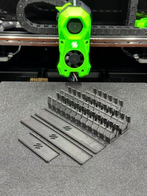
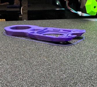
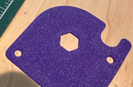
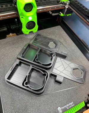
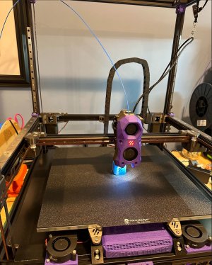
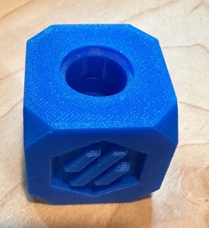
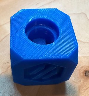
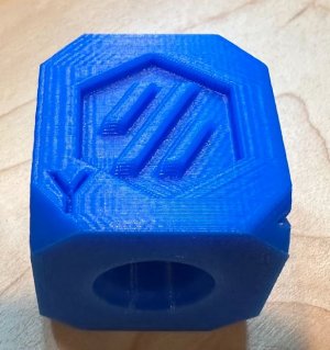
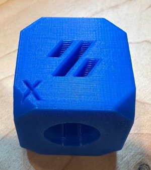
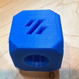
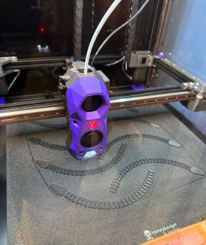
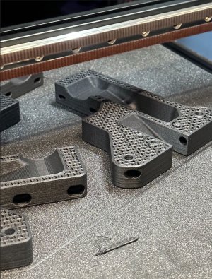
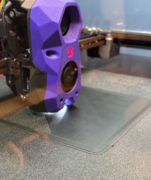
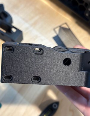
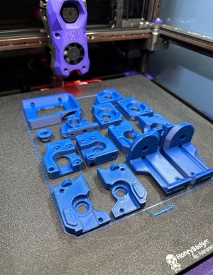
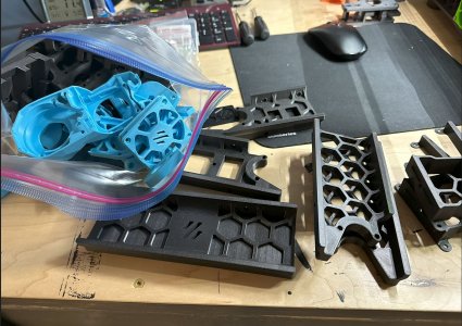
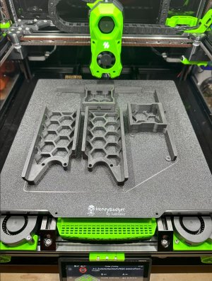
Parts printed on my 300mm in ABS KVP Stellar Black and KVP Sea Blue. Since the wife has to look at them, she got a heavy vote ... I do like the blue though.
Learned a lot from my 300mm build, which was started as a stock kit from voronkits.com. The kit arrived in early December and I completed it (slowly) by late January - have to love holidays and family time! The only thing I added to that build was a SB 2-piece board, LDO toolhead cable, snap latches, bed fans/nevermore, and lighting. I have ~500hrs on it now and recently upgraded the build plate, but other than that all the functional parts were from the formbot kit. All the electronics/fans/motors/etc. were the base kit.
Here is a list of components I have already sourced and acquired, and most of the printing has been done. I have a few things to sort, like which Canbus setup to use, and the associated prints for the mounting/cooling on the toolhead, but the parts are already here so the prints are the last step in the chain, which is under my control at this point. I have been teetering on using my LGX-Lite w/ Stealthburner, but kind of want to leave that for my Tri-zero build that is now waiting on me to complete this one. I expect this build will carry me into the summer and stave off the urge to pick up a X1C ... anyway, here is my build list:
Vendor list:
voronkits.com
fabreeko.com
west3d.com
heatsinkonline.com
amazon.com
aliexpress.com
dfh.fm
350mm Formbot Kit from voronkits.com
Electronics compartment:
BTT Octopus Pro (2x TMC5160 and 4x 2209)
BTT PiTFT50
MW UHP-350-24
MW UHP-350-48
Custom Heatsinks for the UHP supplies to help get more than the derated ~250w and generally stay cooler
TinyFan for electronics bay fans
OctoGlasses mod/fans for HV steppers
Noctua 6025 fans for electronics bay and Noctua 4010 for glasses/Pi
Toolhead:
GDSTime 5015 for Stealthburner
EBB36 Canbus / U2C (Not decided on Can setup quite yet - also have a SB2040 originally planned for my 300 I can use)
TAP kit from LDO (Have a HoneyBadger 50mm rail if I don't like the included LDO) / R8 Tap printed out
Rapido HF PT1000 (Also have a 2nd Revo I can use and a .6 Obxidian laying around as the .4 Obx is in the 300mm)
Bondtech BMG Integrated Drive Gear Assembly (bearings from Amazon) for CW2
LDO-36STH20-1004AHG for CW2 stepper
Rainbow Barf
Wire shroud w/ 3010 fan for Can stepper cooling
Gantry:
LDO 2STH48-2804AH Super Speedy / Super Power High Temp for A/B motors
Titanium Backers
HoneyBadger MGN9H rails for Y
HoneyBadger MGN12H rail for X
Pin Mods for A/B and Rama Front Idlers
Igus GE5C Bearings for Z
Bed:
Kinematics Mount
Bed Wagos
HoneyBadger single Sided black Textured PEI
Ellis Bed Fans (Amazon 5015's for bedfans)
Nevermore w/ GDSTime 5015's
Frame:
3x Daylight XXL strips
Snap Latches
OV5640-style USB camera for overhead / Pi Cam for build-plate level
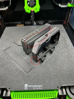
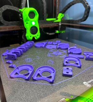
Parts:
Parts printed on my 300mm in ABS KVP Stellar Black and KVP Sea Blue. Since the wife has to look at them, she got a heavy vote ... I do like the blue though.
Attachments
Last edited: