What's new
VORON Design

Register a free account today to become a member! Once signed in, you'll be able to participate on this site by adding your own topics and posts, as well as connect with other members!

Formbot V0.2r1 Kit Build

Perkeo

Member
After receiving my Formbot Voron V0.2r1 kit in two parcels, the kit from Czech Republic warehouse and the printed parts from China, I started building the kit last week.
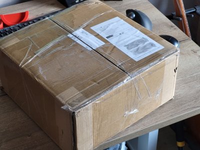
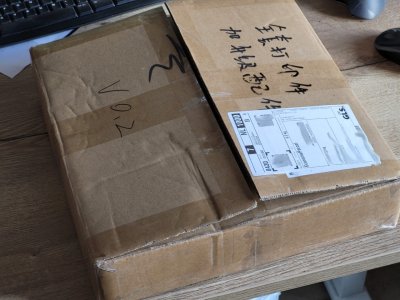

20230831_082511 (FDM).jpg 20230831_082543 (FDM).jpg

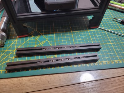
Extrusions looked very good, clean and straight cuts with the edges anodized.
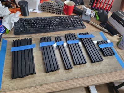
20230901_150319 (FDM).jpg

I wanted the M2 Nut Adapter and No_Drop_Nuts and other small prints to be printed in ABS instead of the regular PLA I printed so far, thus went with black eSun ABS+ printed on my Ender3 Pro. With change of a printer, wanted to have a try with a different slicer as well so changed from Cura to SuperSlicer. I went with the Voron PIF settings and standard ABS setting from SuperSlicer (245C extruder and 90C bed). I don't think my Ender 3 reached 245C because it stopped at 235C which I think is the maximum I specified in Marlin firmware. Still these small parts just printed fine, so did not bother changing anything else.
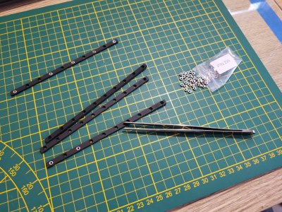
20230902_083305 (FDM).jpg

Not sure if is really needed, but will apply some loctite on metal-metal connections. The PLTight (or Vibra Tite) VC-3 supposedly is safe to use on ABS as well and can be re-adjusted a couple of times!
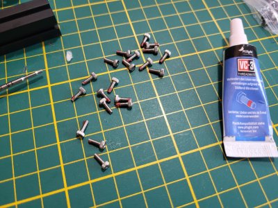
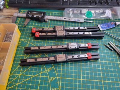
20230902_092137 (FDM).jpg 20230902_110403 (FDM).jpg

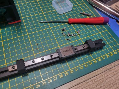
One linear rails in the kit is marked as pre-loaded and will be used on the X-axis.
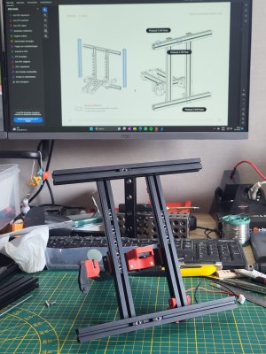
20230903_103322 (FDM).jpg

Plenty of preloaded nuts with the very handy No_Drop_Nuts.
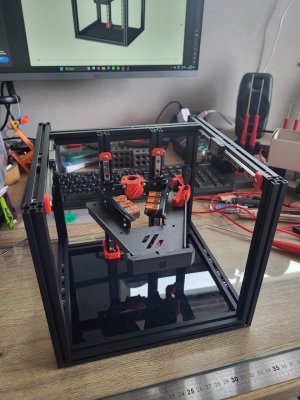
20230903_164028 (FDM).jpg

And we have a frame with Kirigami bed. Next step will be the A/B Drives and Idlers.
 
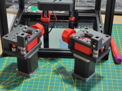
Here are the motors.

20230903_201445 (FDM).jpg

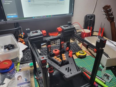
And the motors and Idlers on the frame.

20230903_205200 (FDM).jpg

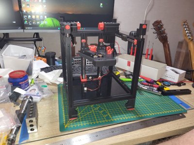
Feets up and down on the ground.

20230903_220112 (FDM).jpg 20230903_220155 (FDM).jpg

In this last photo, you may have noticed I changed wago mount that I mistakenly mounted upside down. A bit difficult to get the wires in and secured with the bed above the clips. :oops:

This is where I leave it for now, time for my own feet up. :D Next steps according to the manual are Z-lead screw and then on to the X-axis!
 
The building process is somewhat addictive. It is like an Meccano or Lego set from the past where you wanted to rush the building to get to the finished end result! 🤔

But, not rushing anything here, steady progress during which I actually have a live stream of a build playing on YouTube to keep pace and potentially catch any mistakes rather sooner than later. This is actually how I notices I had the wago clamps upside down. 👌

20230905_195816 (FDM).jpg

Mounting the marked X-axis which has the carriage with a little pre-load. Makes me wonder why all nuts need to be loaded here and on the Z- and Y-axis every other position with a nut was skipped?!

20230905_214219 (FDM).jpg

In the top extrusion pre-loading the three nuts for the panel mounts (although I am thinking to go for the zero panels), but also thee additional nuts to be able to attach the V0 Handles Slim at a later stage.
20230905_214933 (FDM).jpg

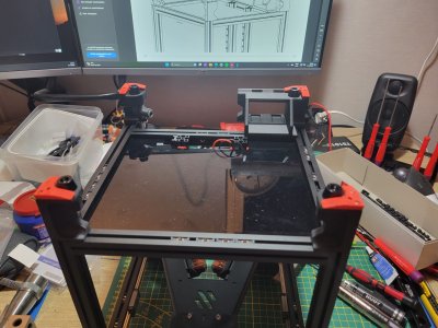
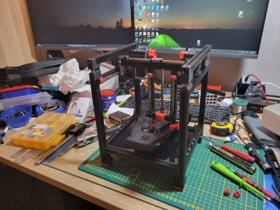
And the X-axis mounted and frame completed. Next are the belts, but leaving that for the next time!
 
Belts & Bed
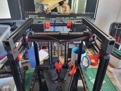
The belts had me worries a little bit, but were pretty easy to install in the end.

20230906_174746 (FDM).jpg

Routing of the belts is very good described in the manual. Little trick at the motors is to stick the belts up out of the motor, make a large loop and push them back down at the other side.. And only then route the belt around the pulley.

20230906_175654 (FDM).jpg

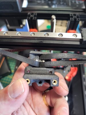
Attaching the belts, I left the "MakerBeam XL" Nuts away to be able to easily push the belts through the X-carriage. Attaching the "MakerBeam XL" Nuts I paid attention to have the sharp edges (the nuts are stamped parts with a sharp and a more round edge) not touching the belts.

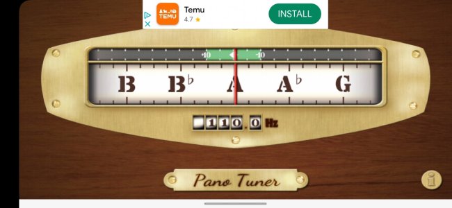
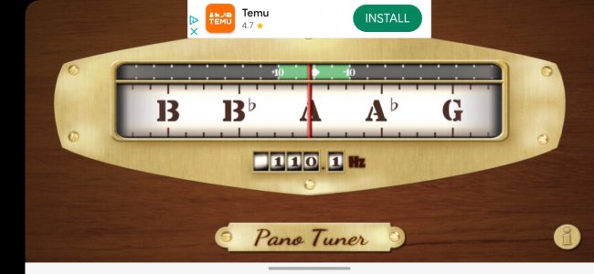
I cut both belts at exactly the same length making the initial tensioning and the X-carriage and then at the motors very easy. I was curious whether I could get the 110Hz measured. Pany Tuner is a great app that I use with my guitar playing as well. It keeps the measured frequency when the tone died.

Proof of both belts at 110Hz 😁

Screenshot_20230906_184331_Pano Tuner (FDM).jpg

Screenshot_20230906_184448_Pano Tuner (FDM).jpg

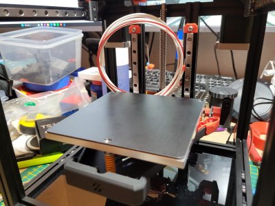
Sticking the heater and the magnetic bed to the aluminum plate went pretty well. After cleaning the plate with 99,9% Isopropanol it was a matter of sticking one time, no pulling loose again, jus sticking it one time!

20230906_210547 (FDM).jpg

Next up is the Print Head!
 
Print Head
So far the build went like a breeze. The printhead caused some more difficulties!

Getting the parts ready
20230908_150430 (FDM).jpg

Putting them in the right order in
20230908_150451 (FDM).jpg

Putting the Mid Body on top. Although all the parts look very good, I had some minor work of scraping some edges to get this piece to fit snuggly on top.
20230908_152115 (FDM).jpg

Then attaching the Print Head and setting the 50T gear spacing
20230908_155225 (FDM).jpg

20230908_155413 (FDM).jpg

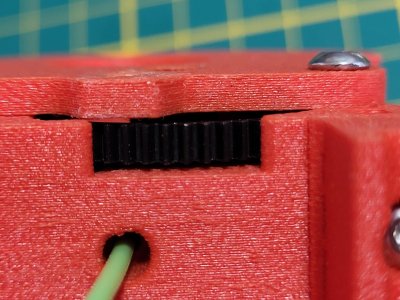
At this point in time, with the 5 steps above, I had put the aprts together already 10 times before I was satisfied. You can also already see that the hole for the PTFE tube isn't exactly round causing that the PTFE tube would not fit. Using a small 4mm drill as a reamer solved this problem as well. I also used some Capricorn Bowden Tubing I had, which was ever so slightly smaller in diameter.

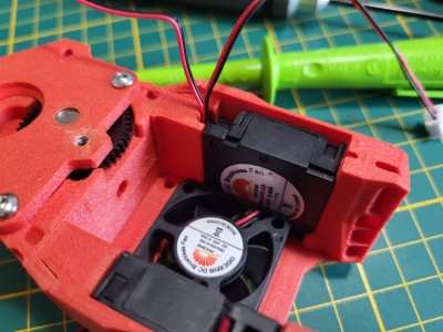
Then on to the fans, finding the right rotations of the fans, cable routing and correct fit was a bit of a puzzle as well before everything was mounted OK.


20230908_162917 (FDM).jpg

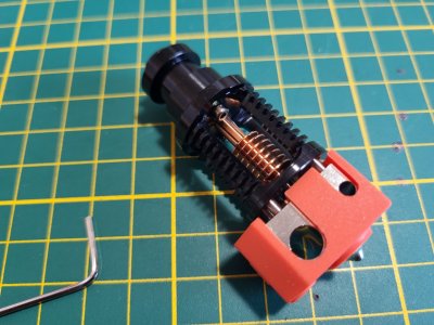
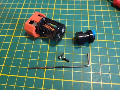
This is the Pheatus Dragon Hotend. Before mounting, the PTFE coupling needed to be removed.
20230908_170444 (FDM).jpg
20230908_170552 (FDM).jpg

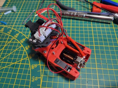
And the toolhead completed. The PCB Mount on the picture was not included in the Formbot Kit. These flat parts work very well on my Ender 3 Pro without enclossure,..

20230908_191137 (FDM).jpg

The PCB mounts need to be detached again before mounting on the X-carriage.

Let's see whether I can get to a working printer over the weekend,...
 
Last edited:
The build is definitely becoming more challenging, progress feels a lot slower. A big compliment to the Voron team for a very good manual, you can see that on other parts that are not yet in the manual, e.g. the Kirigami bed, you need to have a good look yourself!

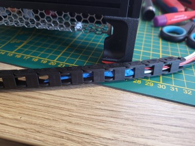
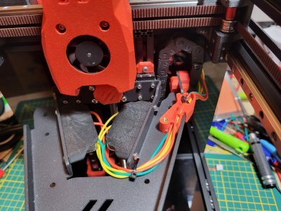
I had skipped the wiring with the Wago clamps during the Kirigami bed install, so had to get that done now before being continuing with the electronics. It started with cutting the bed heater and thermistor wires short and connecting them to the Wago clamps. Taping the wires together I fed them through the cable chain to remove them within the hour because they were to short to have a proper routing and cable management to the MCU.

20230909_154326 (FDM).jpg

Still waiting for the Heluflon-FEP wire from Aliepxress, so had to use slicon wire instead for now. Securing them nicely to the Kirgami bed with the rie-wrap options provided.

20230909_205605 (FDM).jpg

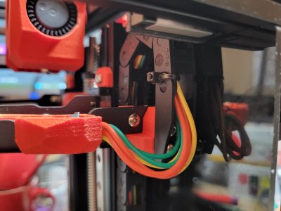
I would like to see a strain relief going into cable chain, would be a good further upgrade to the part that now hold the cable chain. Perhaps something for myself to design later on and contribute back to the community 🤓.This time the easy way out by tie-wrapping to the cable chain itself.

20230909_205626 (FDM).jpg

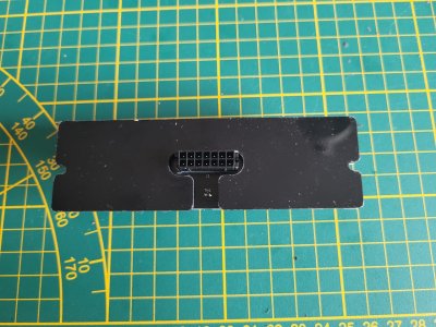
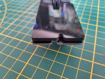
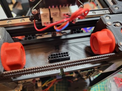
The Formbot kit came with the umbilical mod, very nice! Unfortunately the polycarbonate cover is mirrored incorrectly and cannot be fit properly.

20230909_091009 (FDM).jpg

20230909_091131 (FDM).jpg

After a couple of failed attempts, my Ender 3 Pro could also print this part. Adhesion to the glass bed is however enormous. It is almost impossible to detach the part of the glass bed. Even when using 3DLAC spray.

20230909_204314 (FDM).jpg

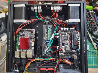
The on to the electronics. I would like to use the cable duct mod with Klipper Expander attached (click), but will not try to print this cable duct on the Ender. To be able to change easily later on, I will use similar positions for the Pi, Pico and Klipper Expander boards.

20230909_131639 (FDM).jpg

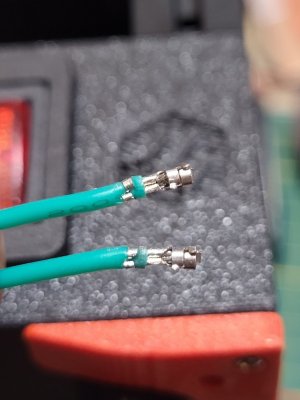
Then onto some really nitty gritty, needing reading glasses work. Crimping some JST XH connectors,.... The first two must have costed me more than an hour and several attempts

But not looking to bad, I think,...
20230909_203813 (FDM).jpg

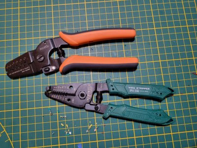
Using these two tools. Engineer PA-06 wire stripper and Iwiss IWS-2820M crimper. Using the 1.3mm setting for the wire crimp and 1,6mm setting for the insulation crimp.

20230909_204752 (FDM).jpg

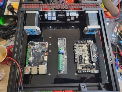
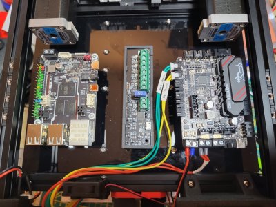
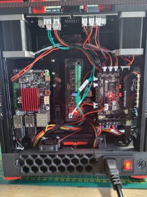
And this is the electronics bay with the very few wires connected at this moment. When I can (when making the wires myself) I will also print on shrink sleeves. See this great video to be able to use cheap cassettes in a Brother labelwriter (Voltlog #238 - Finally Printing Shrink Tube Labels With A Brother Printer)!

20230909_204026 (FDM).jpg

Hopefully more work and progress tomorrow again!
 
Some more building today! The V0.2 may be small printer, but is definitely no small work to get it up and running!

Initial progress was good with connecting more of the wiring.

20230910_131405 (FDM).jpg

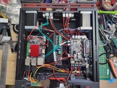
And zip-tying everything down. It actually looks pretty decent and I might even skip the cable ducts.

20230910_135933 (FDM).jpg

After double checking all connections one more time, it was power-up time!!

20230910_153014 (FDM).jpg

Lights and no smoke! Yeah!! 👌

But that didn't mean that there were no wiring issue,..

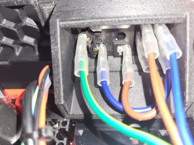
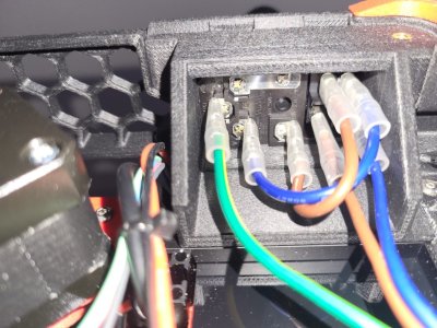
Power button is also lighting up when powered down
Because I had the same problem after building my CNC controller (click- sorry, only in Dutch), this problem was easily resolved.

From the initial wiring
20230910_162001 (FDM).jpg

to the following wiring
20230910_164448 (FDM).jpg

MCU 'mcu' shutdown: ADC out of range
This error message is displayed when a heater is exceeding its set temperure range in the printer.cfg file, but appearantly as well when an analog pin is floating or not connected correctly. Since I did not turn on either bed or nozzle, it must be the wiring. Well if you did not put in the little thermistor in the heater itself,.... :sleep:. OK, so after removing the print head and hotend, putting the thermistor in and putting everything together, this was another problem fixed. 💪

Display V0
After initial cofiguration of the printer.cfg file, I could not get Mainsail to start-up and connect to the printer. Only after a second round of flashing and incrementally changing the printer.cfg file with restarts after every step, I came to the conclusion that the Display itself of course cannot be plug-and-play, there a more controller thingies to be flashed,...

Initial Startup
Just starting this process now. Temperature checks done, nozzle heater is working, fans are working, X, Y and Z-stepper motors have gone through the Buzz test.

Next-up is the sensorless endstops configuration, but better not get that started late in the evening. The finish line is in sight, but in Dutch 'de laatste loodjes wegen het zwaarst' which I think translates into 'the last mile is the longest'...

20230910_224153 (FDM).jpg

To be continued...
 
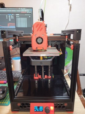
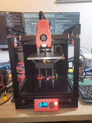
It's alive!!

20230911_202112 (FDM).jpg

From where I left it, there was only very minor work left to be done. Basically just meticulously following the Initial Startup from the VoronDesign page.

The sensorless homing that got me worried a little bit was basically all pre-configures, like most of all the other Initial Startup checks. Nice! :cool:

In the homing macro the (restricted) homing current per X- and Y-direction is specified. I had mistaken this for the actual current and thought the 0,7 from below code was the restricted motor current. But this is actually the factor the running motor current is limited, thus not 0,7A, but factor 0,7 = 70%. Watching part of the the live-stream of @BallisticTech made this clear.

{% set HOME_CURRENT = 0.7 %}

I did not find it in the Initial Startup text, but remembered to torque down the nozzle after pre-heating. Heating to 270C and the little natural overshoot of a couple of degrees crashed Mainsail and stopped the Printer, so tested that feature as well. With the nozzle still at temperature, I could torque it to 2,5Nm.

Then some Z-height and bed_screws levelling and on to the E-step calibration which needed no, but then also exactly no change whatsoever. I extruded 150mm of filament at 1mm/sec @ 200C for the green PLA shown above and it exactly extruded the 150mm. Must be my lucky day 👻

In Superslicer I chose the standard Voron V0 with 0,4mm nozzle configuration and generic PLA, sliced the “voron_design_cube_v7.stl” test cube and sent it directly from Superslicer to the printer. The print time of 3h56 will need some tuning I guess 😇. I now set the speed factor to 150% during the print and will let it finish tonight.

Does anyone have a Superslicer configuration for Voron V0,2r1 or some good starting values? Or is it best to go through the Ellis Tuning Guide now?
 
Both Steve and Nero have V2.4 build series and I think one of Nero's is a Formbot from a while ago. Really any of them should be a good guide. The only differences I think will be in specifics of electronics components and some wiring. Their recent ones are LDO kits, which have a few added goodies in that department.
 
Both Steve and Nero have V2.4 build series and I think one of Nero's is a Formbot from a while ago. Really any of them should be a good guide. The only differences I think will be in specifics of electronics components and some wiring. Their recent ones are LDO kits, which have a few added goodies in that department.

Thanks! Jusst looked up the streams of Steve Builds and Nero 3D and both are LDO kits with first streams of December 2021 and February 2022. Also found a little bit older one of a Formbot build with first stream of June 2021 of Thomas Sanladerer: Made with Layers. So enough material to play along during my build, if and when my kit is shipped. I guess ordering it during the China National Holiday season (Oct 1 - Oct 6) is not helpful, even when the kit should ship from Czech Republic. 🤔
Just as I was posting my serial request this evening, I saw that you just had done the same. Turn around time for my serial request was very short.

Welcome my V0.3106 !

I guess a next mod should be the serial number plate. Is there a multi colour serial plate STL? Never done a filament change during print and I guess a multi colour serial plate might be a nice challenge!
 
:ROFLMAO: Your V0 is the very next one processed after mine: V0.3105.
😇 Its a small world, also on Reddit. Instantly recognized your post on Reddit. I am in good company with my serial number. 🤝

Will have a look at the serial number plate on Github and check if I can make it into a four digit version.
 
The build is definitely becoming more challenging, progress feels a lot slower. A big compliment to the Voron team for a very good manual, you can see that on other parts that are not yet in the manual, e.g. the Kirigami bed, you need to have a good look yourself!

I had skipped the wiring with the Wago clamps during the Kirigami bed install, so had to get that done now before being continuing with the electronics. It started with cutting the bed heater and thermistor wires short and connecting them to the Wago clamps. Taping the wires together I fed them through the cable chain to remove them within the hour because they were to short to have a proper routing and cable management to the MCU.
View attachment 3163

Still waiting for the Heluflon-FEP wire from Aliepxress, so had to use slicon wire instead for now. Securing them nicely to the Kirgami bed with the rie-wrap options provided.

View attachment 3156

I would like to see a strain relief going into cable chain, would be a good further upgrade to the part that now hold the cable chain. Perhaps something for myself to design later on and contribute back to the community 🤓.This time the easy way out by tie-wrapping to the cable chain itself.

View attachment 3157

The Formbot kit came with the umbilical mod, very nice! Unfortunately the polycarbonate cover is mirrored incorrectly and cannot be fit properly.

View attachment 3165

View attachment 3164

After a couple of failed attempts, my Ender 3 Pro could also print this part. Adhesion to the glass bed is however enormous. It is almost impossible to detach the part of the glass bed. Even when using 3DLAC spray.

View attachment 3161

The on to the electronics. I would like to use the cable duct mod with Klipper Expander attached (click), but will not try to print this cable duct on the Ender. To be able to change easily later on, I will use similar positions for the Pi, Pico and Klipper Expander boards.

View attachment 3158

Then onto some really nitty gritty, needing reading glasses work. Crimping some JST XH connectors,.... The first two must have costed me more than an hour and several attempts

But not looking to bad, I think,...
View attachment 3162

Using these two tools. Engineer PA-06 wire stripper and Iwiss IWS-2820M crimper. Using the 1.3mm setting for the wire crimp and 1,6mm setting for the insulation crimp.

View attachment 3159

And this is the electronics bay with the very few wires connected at this moment. When I can (when making the wires myself) I will also print on shrink sleeves. See this great video to be able to use cheap cassettes in a Brother labelwriter (Voltlog #238 - Finally Printing Shrink Tube Labels With A Brother Printer)!

View attachment 3160

Hopefully more work and progress tomorrow again!
I got the Formbot3D V0.2R1 kit also, but can't seem to find that board you hav ethere in the middle...
Is that a seperate Mod you installed?
 
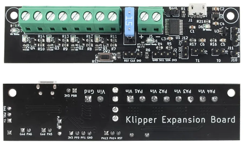
Indeed, you are referring to the Klipper Exapander board which is an addition to the kit. It is not required, but a good mod to have more outputs for fans, lights and it also gives two more thermistor inputs.

This is the official GitHub site of the Klipper Expander

And this is a one of many offers on AliExpress, but one I have ordered and got really fast shipping times to Netherlands.

2023-10-19 19_24_31-Fysetc 1Pcs Voron 3d Printer Stm32f042f6p6 Mcu Klipper Expander Hoge Kwali...png

Carefully check and connect the input (to the right of the blue fuse) and outputs (to the left of the blue fuse) and notice that positive and negative connections have different order. Don't ask how I know and noticed,... 👻
 
Top