What's new
VORON Design

Register a free account today to become a member! Once signed in, you'll be able to participate on this site by adding your own topics and posts, as well as connect with other members!

Goldie - the 350 Voron 2.4 R2 Fysetc kit

After the main activity yesterday, all work that was done was the assembly the klicky-probe.
I decided to go with the Klicky-NG but the Fysetc included kit was for the original mounts so a lot of the provided hardware is not needed however you need some extra M2 selftapping screws.
As gantry-mount I started with the fixed mount.
I haven't thought of extra mods like brushes or purge buckets, so this will be ok for a starter.

Printing ABS on the E3Max is not providing any good prints and as I got the aluminium part kit I decided to just print the bare minimum parts in PETG and treat them as "wasteable".
As soon as I have Goldie up and running I will print the parts in ABS.

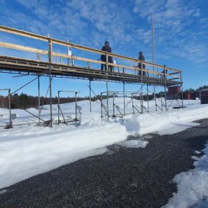
I always forget to take pictures when shooting. Managed to get one at least when the round was almost over.
Sunny day with a lot of snow made this course quite hard as the orange clay was hard to see from above. :)

s-20230410_142849.jpg

EDIT: Forgot to tell, the wires for the Klicky-probe that Fysetc provided are a little bit too thin as the magnets didn't had 100% contact, so I had to strip the wires to double length, fold in half and twist it so I got at least double area.
Now it has the required contact so when doing the conductivity test on the magnets it is 100%.
 
Last edited:
At first I thought I would start by installing the wire-harness and PCB that came with the kit, even though I already decided I will use CAN with this printer.
But as I hate to redo work, I changed my mind and decided to install CAN from start.
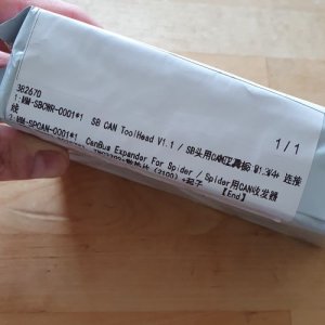
As I will use the Linux-box with three different printers, I don't want to have 5-6 USB cables attached to it, so as the Fysetc Spider has a CAN interface I ordered the required CANBUS expander module and a SB CAN Toolhead board from Fysetc. They have already passed customs, so if we are lucky it could arrive before the weekend.

So today I re-flashed the motherboard with CanBoot and a new Klipper image as well as created a stub for a shell script to flash the motherboard and toolhead (as I will forget all the commands and most probably where I found them 😁).

Until now, I have used Cura with my Ender 3 Max and it has worked ok. But now I felt that it was time to upgrade.
I installed and configured Superslicer, and created an almost exact copy of my Cura profile for the PETG I have and tried it out.
It was really a step up, after tweaking the X-Y settings, I got really nice prints with an error of 0.02-0.04 mm on all edges as well as holes.

The only thing that wasn't really good was the Z height of my test print. The model had 3 mm but my prints came out with a height of 3.3 mm but if I slice and use CURA it is more or less correct.
If anyone has an idea on how to correct that, I appreciate every hint or suggestion.

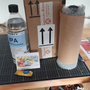
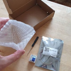
Finally in the afternoon, the phone beeped and Yeay! We got a delivery!
Over and above the Isopropanol that I waited for, it had a Happy Eastern card and some candy! 🥰
What a nice surprise!

I bought the IPA from a Paint Shop down south of in Sweden for a really good bargain.
Well packed as well.

s-20230412_170634.jpg

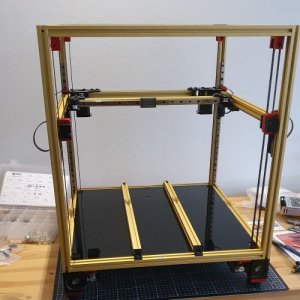
So, the work with cleaning and greasing the rails as well as finalizing the assembly of the frame and gantry began.

In the middle of work the manager showed up and inspected the work.
s-20230412_170638.jpg

He did the QC and approved the work. 😍

So now, it almost looks like a printer!


s-20230412_230243.jpg
 
Houston, we have a problem.... or a warning. This is a long one!


Time for an uppdate.

On Saturday the rest of the parts where installed.
The gantry was squared and tuned in. Belt where tensionen and over to the klicky.

Here we found the first challenge. The klicky-NG.

During installation I always do testing. We can call it unit testing as done in software development.
I noticed that the probe attached perfectly but no connection!
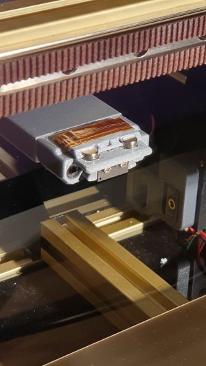
If measured it works so after a lot of investigation I found that when attached I was a little play between the probe and mount which ment that probe where attached but with an angle so that the magnets didn't have metal to metal contact .
To fix that I had to use some capton tape to put the probe at the correct angle when attaching it. That will be addressed when I can print ABS.

Ok, fixed that and got the assembly done so next electronics and wiring.
Everything went without any hassle went to bed quite late but happy.
The only little thing I did change was that the compartment fan was configured as a heater_fan in printer.cfg and turned on only when the bed got to 45C or higher.
Thought that was a little bit stupid because its main job is to keep the electronics cool and it the printer is on without the bed the temperature in the compartment could still be too hot as it is quite a closed space.
Also the mcu do have a temperature sensor, so changed the config so that the fan is defined as a temperature_fan and will work to keep the mcu temperature at 35C maximum.

New day and boy today did we get a challenge.

As the CAN tool head didn't arrive I decided to temporarily wire up the regular PCB so we could do the initial setup and pid tuning and rotation distance tuning.

So started following the Initial startup documentation on Voron docs the motors got buzzed. CHECK.
Homing, did finalised sensorless homing setup with threshold tuning, CHECK.
Z-endstop CHECK.
Perfect, Goldie can now home his axis. 🤩

Next, setup Klicky configuration. While doing that I used for sort of "stress testing" I homed the axis in between. Old habit, it takes some more time but usually pays off in the end.
During one of those homing sequences, instead of homing the carriage did a very strange move.
I flipped the emergency stop and wondered "what the hell....?"
I used the emergency button on the display and the Linux box had no communication with the board. 🤯

Reboot and a G28. Works!
Many people would probably be happy and carry on with life.... well I didn't.
The whole situation tingled that damn spot I my gut telling me something is wrong.

I skimmed the logs, nothing. I buzzed the motors just to recheck. I issued G28 X, G28 Y, G28 Z... Works.
G28 again. Works.

Well decided to carry on but for every test I also did a homing. And finally, when klicky was up and running and I had done a Quad Gantry Level I issued G28 and BOOM I triggered the error again.
The carriage did a perfect homing on X but when trying Y it just wiggled and then started with Z homing, like if it was homed or that the threshold was wrong.
Hm, checked the rails, belts, tensions etc just to be sure, but it seems this is an electronical problem and not mechanical.
Did a threshold calibration again, nothing changed and worked like a charm.
Did G28, works so let's continue with Auto Z calibration and the stress testing. Issued a lot of G32 and G28 and randomly got the errors but no message or clue to what caused it.

I did found in the sensorless homing configuration a delay time so that the driver could get time to do what ever it needs to do. It was set to 1000. Thought, as looked like the Y was failing directlyr maybe the driver was in a strange state and not done with its work... let's test and pushed that to 2000. Nope. Same issue, only difference it waited longer after a homing X before it started to home Y.

Being distracted with reading and googling as well as testing, one time I was a little slow on the emergency button so I used the one in Mainsail, and not the hardware one on the screen and that actually produced the an ERROR MESSAGE! Yeay, finally.
The log said - Undervoltage.

OK, I did tune the PSU as it was really high.
Could that be wrong? No, had exactly 24V under load but raised it to 24.5 just in case, as it was not spinning any motors just powering the electronics and fans.

The comparment fan did a fantastic job keeping the temperature below 35C even with the bed at 100C during pid tuning and heat soaking before tensioning the screws, so couldn't be that either.

Googled and found one guys talking about the current and Vref. But, as we use TMC2209 and UART, you do control the current via software and it shouldn't be needed to tune the Vref as it has dependency on the current, or maybe I got it wrong?
Well, checked the current settings for the driver and no, everything looked as it should.
I didn't do a Vref test though.

Hm, so managed to get the error message produced one more time, and this time I googled the WHOLE error message (don't ask why I didn't from start 🙈) and found links pointing at the driver. It said Stepper X - Undervoltage along with the usual other stuff we put into the messages. 😁

So swapping the X (B) stepper driver for the E stepper which was attached but unused and Voila! It seems to work.
More stresstesting while setting up the last part of G32 and PRINT_START macros the error popped up again but without any error messages, however this time the carriage after homing X tried in the wrong Y direction and started to Z home. No message but could it be the Y (A) stepper this time?

A couple more stress tests and I got the error message and surely it stated Stepper Y - Undervoltage.
Hm, what to do. I don't have any spare driver and all the others we in use for Z1-4 or X?
Well, let's put it on Z1 (Z) and if that one fails I know the reason.
So turned of power, flipped Goldie on the side and swapped the drivers and started to do really heavy stress testing.
So far, nothing!

I test with heated bed, heated nozzle and bed - PRINT_START after PRINT_START - meaning the following

G32 # homing XYZ, QBL, homing XYZ again after gantry calibration, AUTO Z and finalising with a bed mesh calibration.
PARK # put the head in the center of bed

Very late last night, after I don't know how many print starts, I turned Goldie off. Time for some rest.
Hopefully I found the reason.
The suspected faulty driver that I had to put in Z didn't glitch at all even though I pushed the printer to go up and down fast and long travels.

Looking at Fysetc home page you can't buy any TMC 2209 V3.1 drivers only V3.0 (which has different pinout on the board it seems) and V4.0.
When ordering the CAN bus stuff, I wanted to buy one extra and got a "hello stupid" answer that I could buy a bundle of five V4.0.
When popping the questions about it, no answer what so ever...

Of course, looking through their GITHUB and other places - no information what so ever about the differences between V3.1 and V4.0 and if you could use then interchangeably.
I haven't ask on discord yet, so will pop the question there later on.

For now, I have an almost working printer - at least I do know that Goldie knows how to do sensorless homing, klicky-probe, auto z and bed mesh calibration under stress. :ROFLMAO:
 
Last edited:
Yes! A package arrived in the mail. 🥳

s-20230417_124451.jpg

but noooo, they missed to include the toolhead in the package. 😪


s-20230417_124722.jpg

But no shame on Fysetc. Actually I start to like them.
As said before, I get the feeling they want to be perceived as a serious player and feel they start to live up to it.
Remember dialog from last post where I talked about me asking about the v3.1 and got a strange reply.
I told them I needed one TMC2209 but not V3.0 that I could by in single but a V3.1. Anyway so I ordered one V3.0 and they included one V4.0!

Nice customer work Fysetc!!! Me like. 💯💯💯(y)

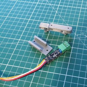
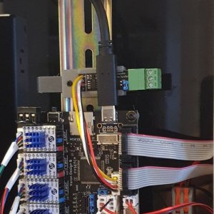
Ok, so no CAN assembly then until I get the tool head, well I will design some bracket and see where to fasten the Expander board to the DIN-rail, print and then assemble that.
 
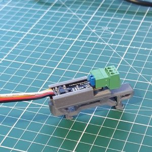
Fired up Fusion360 and created this simple bracket that mounts on top of the pcb din clip from the Voron STLs.

s-20230417_195812.jpgs-20230417_200207.jpg

And this is how it was fitted in on the printer.

s-20230417_202154.jpg
 
Last edited:
Fysetc has reconised the error and is sending me the Toolhead board. However, Aliexpress says it still not sent... damn, I haven't installed the umbilical chain as I intend to put the CANBUS cable differently so I am hesitating to continue with the first test print.

So instead I have finalised the shell script for flashing over CANBOOT but the CANBOOT is not reliable for some reason.
Currently i states that it flashed:

pw@fidji:~$ python3 $HOME/CanBoot/scripts/flash_can.py -i can0 -u 7926886c2888 -r
/home/pw/CanBoot/scripts/flash_can.py:613: DeprecationWarning: There is no current event loop
loop = asyncio.get_event_loop()
/home/pw/CanBoot/scripts/flash_can.py:278: DeprecationWarning: There is no current event loop
self._reader = asyncio.StreamReader(CAN_READER_LIMIT)
Sending bootloader jump command...
Bootloader request command sent
CAN Flash Success
pw@fidji:~$

but the only thing that happens is that it makes a shutdown and I have to flip the power switch on the printer to restart, and the firmware is not changed:

1682013968041.png

I have no clue if that is CANBOOT that is faulty or it is the fact I run Ubuntu. Why, well Ubuntu has a different way of setting up the network interfaces, it doesn't use /etc/network/interfaces folder hence you can't set the "allow-hotplug" prefix to the can0 interface to fix that the CAN node comes back online after firmware_restart.
Googled the subject and the only thing I find is that hotplug should work in Ubuntu 22.04.

Obviously it does NOT flash my board correctly and get back online.

Workaround so far?
Issuing the command and hope it sets its self in CANBOOT mode and then issue

pw@fidji:~$ python3 $HOME/CanBoot/scripts/flash_can.py -f $HOME/klipper/out/klipper.bin -d /dev/serial/by-id/usb-CanBoot_stm32f446xx_590054001951303439363932-if00
/home/pw/CanBoot/scripts/flash_can.py:613: DeprecationWarning: There is no current event loop
loop = asyncio.get_event_loop()
/home/pw/CanBoot/scripts/flash_can.py:278: DeprecationWarning: There is no current event loop
self._reader = asyncio.StreamReader(CAN_READER_LIMIT)
Attempting to connect to bootloader
CanBoot Connected
Protocol Version: 1.0.0
Block Size: 64 bytes
Application Start: 0x8008000
MCU type: stm32f446xx
Flashing '/home/pw/klipper/out/klipper.bin'...

[##################################################]

Write complete: 3 pages
Verifying (block count = 521)...

[##################################################]

Verification Complete: SHA = 1AB7663461E200ABCF09E21E65C21321AD89C8BA
CAN Flash Success
pw@fidji:~$

Now, it is flashed:
1682015025379.png

Also, as you can see there is a warning for the asyncio objects. It seems to be some deprecation in the latest python3 so I guess the CANBOOT guys will fix that in a later release.
If not, I might need to look into it later.

Damit Fysetc, send me that damn pcb so that I can start 3D print instead of finding thousands of other problems to solve. 👿

Who said building a 3D printer was easy?! 🥳 :ROFLMAO:
 
The CAN bus toolhead is on its way, but seems to end up around May 12-17, so I had to change my plans.
Installed the Toolhead PCB and the cable in a umbilical setup, running through the vent in the rear.
So did the last part of the initial startup - rotation distance and attached the panels and started to tune.
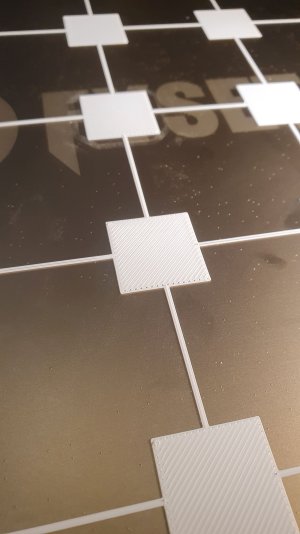
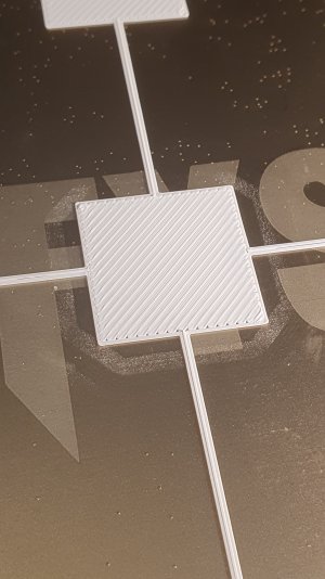
I followed the calibration guide in the Superslicer starting with the extrusion multiplier and ending with calibraration part for dimensional accuracy.

I used some ABS for calibration and test parts, that I got when I bought the Sovol SV03 from a one guy who intended to use it in his production. I think I got like three 1 kg brand new unopened spools.
It is branded as "Scapefill ABS / www.scape.se" but the site doesn't exist anymore and the last reference when googling is around 2020 but not for the ABS so I have no clue if it is good or bad, problems that been found etc.
The filament were label with 245C +/- 10 C for the hotend and 90-110 C for the bed.
Went with 245C /100C to start with and during temperature calibration the 245C seemed to be a good.

Findings:

Travel speed - I have the default configuration in Superslicer for the Voron 2.4. It is FAST!
XY horizontal compansation - Need to tweek but not much
Hole compansation - Need to tweek that too.
Bed adhesion - wonderful, using the smooth side of the PEI sheet and it STICKS!
Top surface - terrible. Need to tweek or re-do some calibration
Elephants foot on several of the lower layers - need to check and correct the bed temperature

During test the y driver started to report Undervoltage and just stop.
Found that the sensorless homing macro set the run current to 0.7 during homing so I cranked that up to the 0.8 amp that is configured for the x-y steppers in printer.cfg and the problem seems to be fixed.
At least I didn't get any troubles during the rest of the time.
 
Ok, so as the Toolhead board was delaying the project, Goldie just sat on the bench without any attention until New Year.

I then had to update the computer and Spider Board with newer versions of Klipper.
Found an oddie, that CANBoot didn't put the board in boot mode, I couldn't understand why? Somethings is odd.

So, as the board didn't want to work, I also updatded CANBoot -> Katapult to see if that changed anything. Nope, but now it is up to date atleast.
Started to work on the Toolhead board and managed to smoke it, as I hot plugged the CAN-cable to it when I where about to flash it.
So, had to order a new one and wait again...

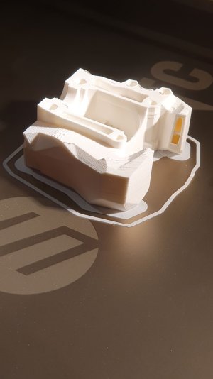
Meanwhile, I thought I would print the Stealthburner (SB) parts in ABS, so re-did the basic calibration of the printer. I just focused on Correct Z-offset calibration, Pressuare Advanced and Extrusion Multiplier as the AXDL sits on the Toolhead board so input shaping will have to wait till I get CAN-bus up and running. The idea is to get the SB up and running and then tune it so I can
20240119_100258.jpg20240119_100312.jpg20240128_190901.jpg
The Klicky-NG where really troublesome from start. Didn't want to work with the docking and un-docking. Found that the printed part was out of tolerance so had to fix it with some kapton tape.
Then after that started it to get a high variance in the probing so I had to restart the jobs almost all the time.
Decided to buy a Chaoticlabs CNC Tap v2 as an upgrade for the SB and leave the klicky track for good.

20240128_191024.jpg

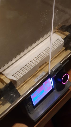
While I was at it, I also printed the Nevermore. The Fysetc kit came with a heat insultator that I installed over the bed heating pad under the bed, and that builds too and the standoffs are to small. Had to order longer from Aliexpress, and will arrive sometime by the end of March.
20240128_190919.jpg
 
So, Stealthburner build.
For the Stealthburner I will go with

Bondtech LGX Lite Pro
Slice Engineering Mosquito hotend
Slice Engineering PT1000 500 degrees temp sensor
Slice Engineering Mosquito 2v 50W heater
Bondtech CHT nozzle
Chaoticlabs CNC Tap V2
Fysetc SB CAN Toolhead

All parts are printed temporarily in the white ABS I got when I bought another printer.

First, I flashed the toolhead and got that up and running. during that work I found the reason CanBoot/Katapult didn't work as expected for me.
Since I use a multi printer setup, stopping the service is different as the one klipper service instance is created for each printer.
So instead of doing a "service stop klipper" one need to do "service stop klipper-Goldie"
With that, everything works great.

NB❗ Fysetc SB Can Toolhead v1.3B says to have a jumper for the 120 Ohm resistor. The board I got was a newer version of the v1.3 but didn't have any jumper or onboard resistor.
Instead it had pads so one can add a resistor. Unfortunately I didn't have a 0805 120 Ohm at home, so hade to order some. Meanwhile, I did a dirty-hack with some Wagos and a couple of resistors in series.

Second, when Can was up and running but the board was still not installed I tested the LGX Lite Pro and did a quick check on the rotation distans. Bondtech suggested 3.99 and that was almost spot on. When assembled I did a new run and got 3.93. That is of course measured with calipers. 😁

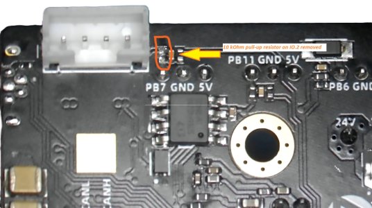
Third, the Fysetc board only has ports with pull-up resistors (4.7 k and 10 k) and if attaching the CNC Tap v2 to those the wire break functionality does work as it needs a pull down port.
So to fix that, I desoldered the 10k pull-up on the IO.2 port on the board. By adding the pull-down in the klipper config, it works as intended.

Fysetc SB Can toolhead v1.3 - remove 10 k pullup.jpg

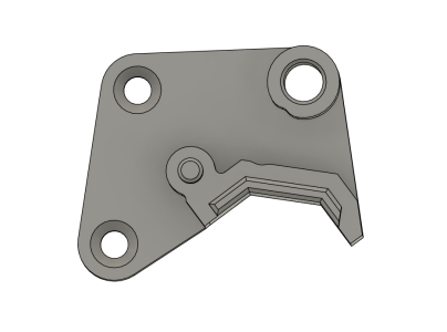
Fourth, I had to adjust the toolhead mount that Bondtech had for the LGX. The ports for the fans and, if I want later, RGB connectors where too close to the LGX Lite mount.
So fired up Fusion 360 and did a fast change.
Skärmbild 2024-02-15 201734.png

Fifth, assemble everything on the printer. Noticed that the CAN cable connector is really in the wrong spot as it hits the back part of the printer when travelling on the highest y-coordinates.
I need to look into that, to see if it can be fixed.
Well, this is how it looks now.
Skärmbild 2024-02-19 210334.png
 
Ok, CAN problems! As soon as I start probing, either when doing Z-homing, QGL or Bed mesh probing I get an error:

"Communication timeout during homing probe"

Checked the cabeling, checked the termination resistance, checked all the CAN related stuff. Nothing.
Started to google around a lot and found a post on the klipper forum about the issue.
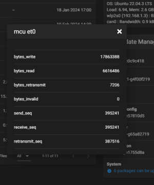
Checked the number of bytes_retransmit and bytes_invalid and as they were ok I seemed to be a non-can related issue.

Skärmbild 2024-02-19 221156.png
Rather it is a kernel related problem, and the workaround that seems to fix it for me to 95% of the times is to raise the TRSYNC_TIMEOUT from 0.025 to 0.050 in the mcu.py file.

pw@fidji:~/klipper/klippy$ grep TRS mcu.py
TRSYNC_TIMEOUT = 0.050

I occasionally get it, but a restart of the print job usually is all I need to do.
So, some statistics now when it is as I want it.

The QGL tolerance is outstanding.
Skärmbild 2024-02-19 171425.png

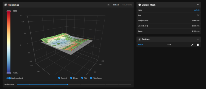
Bedmesh, taken after ~15 minutes of heatsoak is usually around 0.175. After a couple of hours of printing it drops to around 0.110-0.130.
Skärmbild 2024-02-19 210502.png

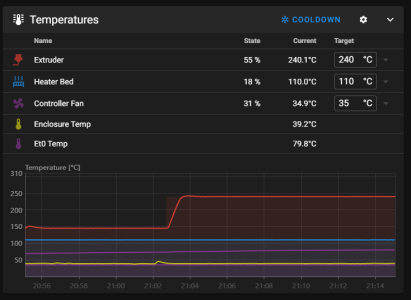
The temperature in the enclosure reaches around 40 degrees and the toolhead has around 80 degrees. So a fan will be installed on the toolhead to cool the extruder motor.
Skärmbild 2024-02-19 211509.png

So now, the REAL tuning started.
 
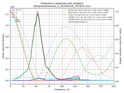
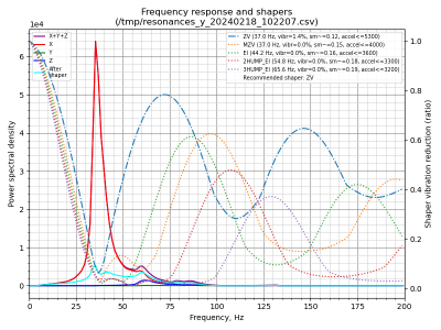
Input shaping. Looks ok. The X-axis has two parts that I will later dig into. The "small bump" before the top and then the "edge" right before it smooths out.
The Y-axis is outstanding. I followed the recommended shaper profiles and set max acceleration to 5300.

shaper_calibrate_x-2024-02-18.pngshaper_calibrate_y-2024-02-18.png

Ellis tuning guide, was traversed and PA as well as EM was tuned again and added to the Superslicer Filament profile.
When done, I started to calibrate the XY compensation as well as Hole compensation. Now the parts is within +/- 0.03 mm. 🥰

So, now the hard tests will start by printing the missing parts, like skirts, panel hinges etc and ordered some Fiberlogy ABS in Onyx black and Burgundy red for those parts.
Tuned the PA and EM for the filament and started to print.

So far, no problems at all. Outstanding performance and tolerances on the parts. So, when everything is done, I will update with a picture and apply for a serial number.
 
Long time, no writing.
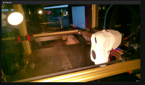
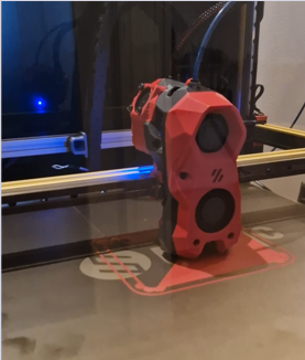
Got his serial, so today he is named Goldie V2.7471 and this is what he looks like now:
1730751543453.png

However, there are still some issues. I had the CAN-error popping up again, when I started to add the Creality printer to the host.
So, they had to run separately.

Ubuntu got updated from 22.04 to 24.04 and then problems started.
First the latest python3 crashed the klipper-installation. An update with kiauh didn't help, then the wireless network crashed when I tried to fix the python problem.
Hint, don't try to remove any python-related stuff from an Ubuntu dist...

Had reinstall the 24.04 server totally, and then re-applied the all my data like CAN-boot, klipper etc from the backup I took.
The python problem still existed, so tried to install everything again with kiauh.
That solved the problems, so klipper and moonraker started again.

But as the CAN network was gone, Goldie didn't start up only E3Max (the creality printer) which runs over USB.
Fixing the CAN-network brought up Goldie and then a homeing. Worked and then QGL - CRASH again.

This time I get the infamous: mcu 'mcu' shutdown: timer too close
And that's where we are now!

Nothing but the klipper, moonraker and mailsail service is running on the host and still the QGL crashes after two-three probings...
All info I find, all ends somehow in this post: https://klipper.discourse.group/t/timer-too-close/6634

I am currently wondering what to do.
The Linux installation is Ubuntu Server 24.04 LTS but no GUI, it crashes cold hence cpu temp 30-35 degrees, mcu 24 degrees, mcu toolhead 25 degrees. No heat on hotend or buildplate...
no load on the cpu, memory available...


Any takers?
 
Top