shipkiller
New member
- Printer Model
- Formbot Voron 2.4 R2 kit
- Extruder Type
- Other
- Cooling Type
- Stealthburner
I recently started a Voron 2.4 R2 build with a kit from Formbot.
Included in the kit:
TAP
Can bus
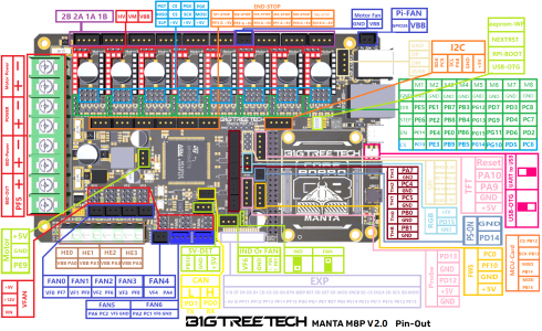
Manta M8p V2.0
For some reason, the kit did not come with a cable harness for the Y-endstop. OK, so I have to build one. Not a big deal.
Documentation says I have to connect the Y-endstop cable to the M2-stop end-stop connector(s).
Since the switch is a two wire switch and the M2-stop is a three pin connector, I am wondering about the connection.
The Manta Pinout shows this connector as: PF3 G +5v
I am going to assume that PF3 is a board mnumonic , G is ground and then +5v.
I am also going to assume that pin one (1) is to the left and is not connected, center pin is ground and the pin three (3) 5v is on the right.
Can anyone tell me if this is correct?
I am also going to assume the TAP is the Z-stop.
Included in the kit:
TAP
Can bus
Manta M8p V2.0
For some reason, the kit did not come with a cable harness for the Y-endstop. OK, so I have to build one. Not a big deal.
Documentation says I have to connect the Y-endstop cable to the M2-stop end-stop connector(s).
Since the switch is a two wire switch and the M2-stop is a three pin connector, I am wondering about the connection.
The Manta Pinout shows this connector as: PF3 G +5v
I am going to assume that PF3 is a board mnumonic , G is ground and then +5v.
I am also going to assume that pin one (1) is to the left and is not connected, center pin is ground and the pin three (3) 5v is on the right.
Can anyone tell me if this is correct?
I am also going to assume the TAP is the Z-stop.