What's new
VORON Design

Register a free account today to become a member! Once signed in, you'll be able to participate on this site by adding your own topics and posts, as well as connect with other members!

Question Neopixels (Rainbow Barf) with 2 Piece Hartk SB board erratic behaviour

Stefa168

Member
Hi, in these days I finished installing on my 2.4 the Stealthburner toolhead.
I am using a PCB by Hartk, in particular the two piece version.
Everything works fine, except for the neopixels.

In particular, the problem appears only if I have the heater cooling fan plugged in (in my case as I needed to use the AUX trace for the tachometer I inverted the two connections, but it shouldn't be an issue).

Here you can see the issue:

I have tried adding a 200 ohm resistor in series with the data line, but it didn't change the behaviour.

By chance, I touched the hotend with my bare fingers, and at first I thought that it was a bad connection.
However, when I began unscrewing the PCB from the stealthburner, I noticed that the issue disappeared as soon as I touched the screw with my allen key.

Here's a video showing what it is happening:

Could it be that there is some grounding issue, or that a capacitor is needed somewhere? I have some knowledge about electronics, and this looks like it could be a capacitor issue.

Any thought?
 
I have the same issue... Following in case someone comments.

Hi, right now I haven't hooked the tachometer pin to the board, but by replacing it with a one-piece board I managed to fix the issue.
I tried mentioning it a couple of times on Discord, but there wasn't a lot of research or activity.
 
By chance, I touched the hotend with my bare fingers, and at first I thought that it was a bad connection.
However, when I began unscrewing the PCB from the stealthburner, I noticed that the issue disappeared as soon as I touched the screw with my allen key.
I have a similar issue with my SB2040 CAN toolhead board. I also can't get the RGB leds on my SB2040 to work, like described here, and what I noticed is that when I touch the traces/contact with my fingers/tweezers etc. the leds "work better" (from blinking only occasionally to blinking frequently...). As this issue is not yet solved further investigation is needed/about to come...
 
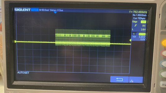
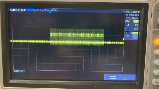
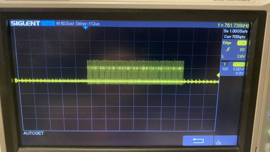
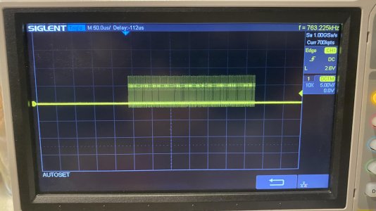
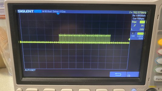
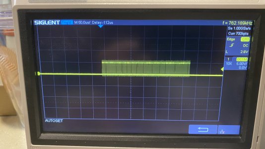
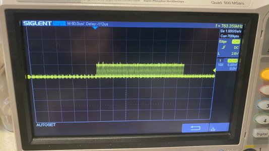
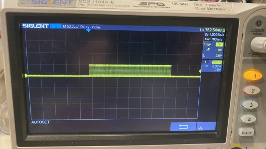
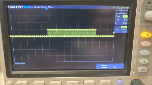
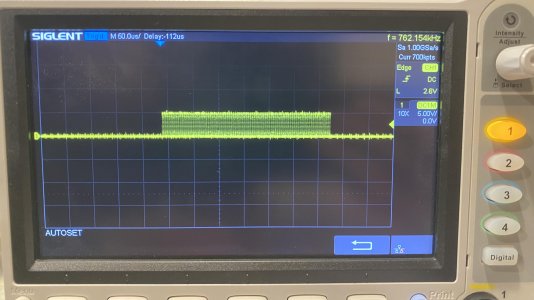
I had a similar issue today. Mine was caused by the extruder stepper motor. LEDs worked fine and never flickered until extruder stepper driver was enabled, then they flickered like crazy. Probed the LED communication signal at the toolhead with an oscilloscope and when the stepper driver was enabled a lot of noise showed up. It also seemed like the inductance of the wires might be causing issues because there were large voltage spikes to almost 10V. I was able to fix it and basically completely eliminate the flickering by placing a 220 ohm resistor in series with the LEDs data wire near the control board. The images below show the oscilloscope measurements for various scenarios.

No resistor, no capacitor, stepper disabled (low external signal noise, large ripple, voltage spikes up to ~9.5V)
IMG_3393 copy.jpg

No resistor, no capacitor, stepper enabled (external signal noise from stepper, large ripple, voltage spikes up to ~9.5V)
IMG_3394 copy.jpg

100 ohm resistor at toolhead, no capacitor, stepper enabled (less external noise from stepper, slightly reduced ripple, voltage spikes up to ~8V)
IMG_3395 copy.jpg

100 ohm resistor at toolhead, no capacitor, stepper disabled (no external noise, slightly reduced ripple, voltage spikes of ~8V)
IMG_3396 copy.jpg

100 ohm resistor at control board, no capacitor, stepper enabled (less external noise from stepper, greatly reduced ripple, voltage spikes of ~6.5V)
IMG_3397 copy.jpg

100 ohm resistor at control board, no capacitor, stepper disabled (no external noise, greatly reduced ripple, voltage spikes of ~6.5V)
IMG_3398 copy.jpg

220 ohm resistor at control board, no capacitor, stepper enabled (slightly reduced noise, greatly reduced ripple, eliminated voltage spikes)
IMG_3399 copy.jpg

220 ohm resistor at control board, no capacitor, stepper disabled (no external noise, greatly reduced ripple, eliminated voltage spikes)
IMG_3400 copy.jpg

220 ohm resistor at control board, 10pf capacitor at toolhead, stepper enabled (reduced external noise, greatly reduced ripple, eliminated voltage spikes)
IMG_3404 copy.jpg

220 ohm resistor and 10pf capacitor at control board, stepper enabled (almost no external noise, greatly reduced ripple, eliminated voltage spikes)
IMG_3403 copy.jpg


The 220ohm resistor in series with the data line at the control board was the least complicated with the 2nd best results. The 100ohm resistor reduced the noise more than the 220ohm resistor, however the reduced voltage ripple from the 220ohm resistor provides enough of a benefit to outweigh the slightly greater noise.

The 220ohm resistor in series with the data line with a 10pf capacitor placed after the resistor between GND and the data line gave the best results. Noise, voltage ripple, and voltage spikes were almost completely eliminated.

By watching the LEDs it seems that both of the options above perform similarly, with the occasional flicker every now and then (maybe once a minute) so personally I am going with the simpler solution of just a single 220ohm resistor in series with the data line at the control board.

My printer is a 350mm Voron 2.4, the required resistance or capacitance might be different depending on the size of your printer, wiring setup, and source of signal noise.

Hope this helps!
 
Last edited:
By the way, I also should mention that holding an allen key and placing it on the PCB screw would mostly eliminate the flickering of my LEDs also.
 
I just (finally) installed my 2-piece PCB and now am running into this same issue. Incorrect colors and flickering like in the videos above. Poking it with an allen wrench alters the behavior, but doesn't eliminate it completely.
So if I understand @Gunner087 's solution, you insert a 220ohn resistor in the signal wire by the controller board (Octopus, NeoPixel port in my case), correct? Same idea as the original BAT85 diode in the inductive probe wiring.
 
Quick follow up. I have lots of spare 220ohm resistors, so I went ahead and tried adding one right at the controller end of the signal cable. Issue resolved! The Stealthburner w/ Rainbow Barf LEDs are behaving again. Thanks for the solution!
 
Top