What's new
VORON Design

Register a free account today to become a member! Once signed in, you'll be able to participate on this site by adding your own topics and posts, as well as connect with other members!

Trident 250 -- My First Voron

brendanm720

Well-known member
I'm not new to 3D Printing, but I'm new to building 3D Printers. Because I don't have the capability to print ABS, I signed up for PIF back in 2021 when the queue was super long (figuring it would take around a year), and got my kit back before Stealthburner and Trident R1 dropped. 🤦‍♂️ BrewWeasel was my provider, and so far, everything looks fantastic.

This printer was self-sourced over the course of a year or so (to spread out costs) by obtaining the parts and parts kits (hardware, motors, motion, et cetera) in as few shopping trips as possible to save on shipping. West3D, DFH, and KB3D were my primary vendors.

Colors for this build are:
Frame -- LDO Space Gray
Primary -- Matterhackers Build ABS Black
Accent -- KVP Stellar Blue

I'm kind of kicking around a dark gray also for the skirts and the toolhead parts that would usually be the primary color. KVP Battleship is kind of what I have in mind.

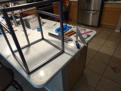
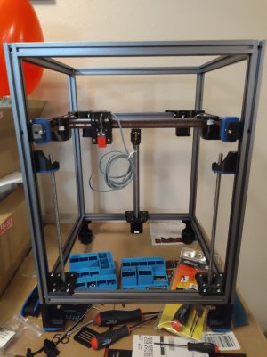
To Kick things off, I put the kids to work opening up hardware and pulling the frame out of the box. The Frame is an LDO Space Gray model, and the Hardware is West3D's BDF Trident hardware kit. There was a bit of a problem in shipping -- The M5x10 Button Head baggie exploded and I gathered them all up and stuck them into a Gridfinity box.
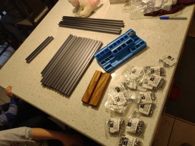
IMG_20230128_124157391.jpg

So, armed with my speed square, some miscellaneous Allen Keys, and my wife's pretty, pretty, pink scale, I fought the frame (and the kids).
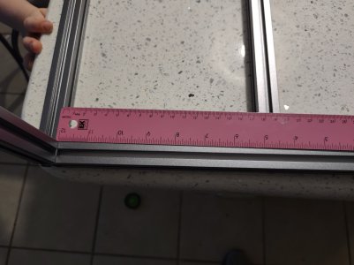
IMG_20230128_130925220.jpg
IMG_20230128_133151725.jpg

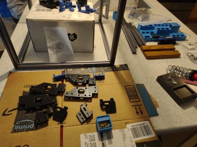
Time for the Front Idlers and the Motor Mounts.
IMG_20230128_134714869.jpg

The Motor Mounts went very smoothly -- The only thing missing was the pulley jig (I didn't think to print it beforehand, and my PIF kit didn't come with it). The pulleys are easy enough to eyeball, though.

The Front Idlers? Not so easy. There were many profanities and weeping and gnashing of teeth -- the bearing stack went everywhere when I pulled the bolt and put the adjustment piece on. Several times. After trying things several different ways, I ended up assembling all three printed parts with the adjuster all the way over to one side, and then building the bearing stack a piece at a time while inserting the bolt a little bit at a time to capture each new piece. But, I got it. Eventually. I even spun up Steve's first Trident Build Stream on the TV to see how he was doing those things just in case there was something I was missing.
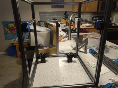
IMG_20230128_153928025.jpg

Time to install all of the things. I'm gonna do Tap later and figure now is the time to add the extra fasteners. One of these M3 roll-in T-Nuts had a malformed wallowed-out hole and I had to manhandle that thing back out and replace it. That was not terribly fun.
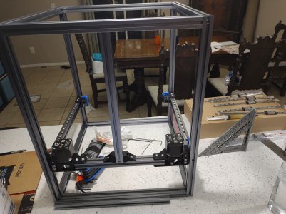
IMG_20230128_200109555.jpg

If Star Trek Picard uses 3D Printers as replicators, can I pretend my little Flashforge is a replicator too? "Computer: Linear Rail Jigs".
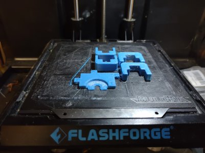
IMG_20230128_200607087.jpg

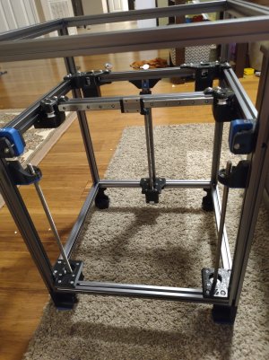
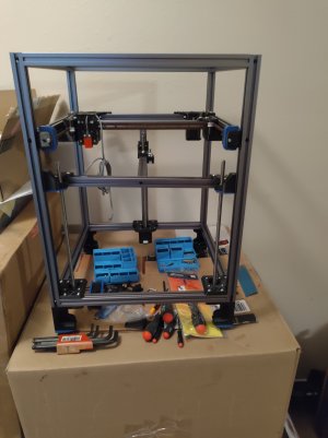
By this point, it was getting kind of late, so I didn't take any pictures until the end. I didn't realize that West3D ships their house brand rails out fully greased and ready to go, so that was nice. I got the Y Rails on, put on the Z rails, carriages, and steppers, and managed to put the wrong rear carriage mount (I needed to install the 3 hole version. Also, I needed to put the heat sets in and didn't...) And I missed the part in the manual where it says to not tighten down the nylock nuts on the Z leadscrew nuts. So I gotta fix those when I put the right rear carriage mount on.
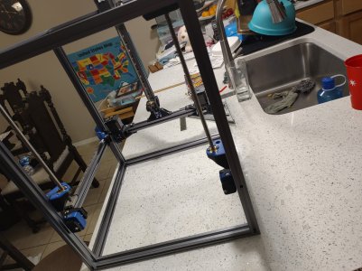
IMG_20230129_002726837.jpg

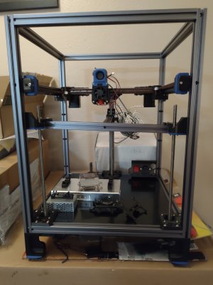
I built the feet the other day and put them on, but didn't take a picture. I'll start with that one for next time.
 
Looks great so far! I am guessing you are just using the kitchen because of the flat countertops? I would not be allowed to do that for more then a day or two.

Can't wait for you to be able to say "It's Alive"
 
Looks great so far! I am guessing you are just using the kitchen because of the flat countertops? I would not be allowed to do that for more then a day or two.
Yeah... I'm in the kitchen because of the quartz. I tried to buy a small remnant from the guys who did the counters, and while they were cool with selling me one, they had to come out and install it somewhere. They had a bad time a while back and now everything they sell has to be glued down, which doesn't exactly work well with our use case. Oh well.

I can't get away with leaving stuff on the counter long-term either. I was mostly cleaned up when I took that last picture.

Can't wait for you to be able to say "It's Alive"
Me neither.
 
Update 2

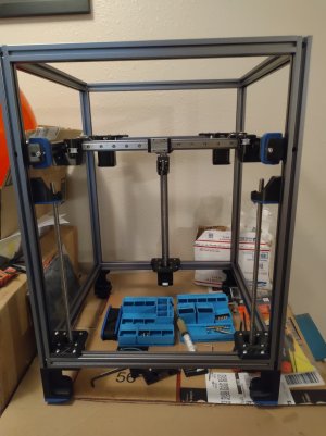
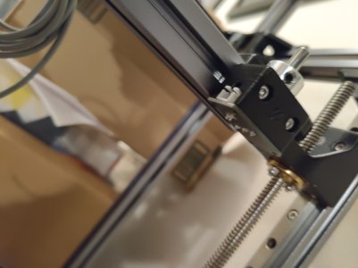
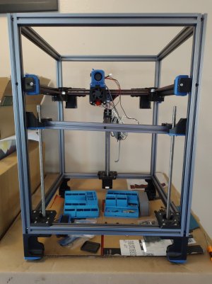
I took the time to swap on the correct rear carriage mount (with heat sets this time) and loosened up the front leadscrew nut retaining screws as per the manual, which I missed last time, and grabbed the X extrusion and started putting T-Nuts in it. I installed enough to populate all of the holes in the rail, because I'm planning on going to Tap later when I swap over to SB and CW2.

Then I looked at the manual and grabbed the MGN mount parts for the toolhead, and the cable chain bridge thingie and put heat sets in those.

After unplugging the iron, greased my MGN12 rail.

Because of an inventory oopsie during the Black Friday weekend, Daniel at West3D was nice enough to swap in a Berserker MGN12 in lieu of the house brand MGN12 Rail I ordered. The Berserker was not pre-lubed like the house brand MGN9 rails were, but is a really nice rail. Really nice.

I ran into two more M3 Roll-in T-Nuts with wallowed out/oversize holes, so that was fun (and a bit greasy) to sort out. The T-Nuts I swapped in are working nicely.

The X/Y Joints went together well with no complaints, and mounted up fine.

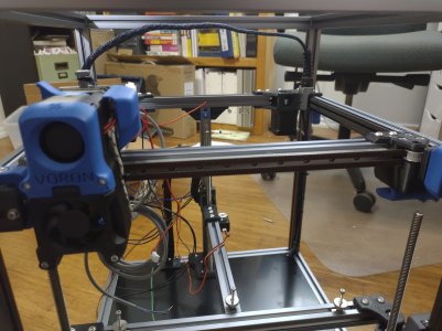
Eagle-eyed viewers will note that I did not mount the Cable Chain Bridge thingie. I'm going to go Canbus to the Toolhead (with an umbilical), but I hadn't yet settled on how I was going to do the X and Y endstops. While I was assembling, I made the decision to omit the cable chains completely and go with Sensorless X/Y Homing. I read through Clee's guide, and I don't see any deal breakers in there, so I will be not using the endstop board that came in my harness.

I mounted everything up, tightened up the screws, and cleaned up for the night.

IMG_20230209_232249967.jpg
IMG_20230209_233013695.jpg
 
Last edited:
This is looking great! Thank you for sharing I love these build logs! So happy we could play a part in this one! Keep up the good work!
Thanks! I'm pretty happy with everything I've gotten from you guys so far!


Looking great! I can't go back to endstops after going Sensorless.
It seems like an elegant solution and the less wire I need to run, the better. Happily, I grabbed 2209s for the Octopus.
 
Update 3

I didn't get much done this weekend -- My parents are in town, and we went on a family outing on Saturday and a big chunk of time was spent on Sunday troubleshooting my TV Antenna's reception. (I've got it narrowed down to the amp, or maybe the cable run. I need to dig out my snap-n-seal terminators and crimper and crawl back up into the attic and reterminate a few ends before buying a new amp. Though, the VHF stuff is not coming in at all, and the UHF stuff is... sketchy, so I think it's probably the amp.) But enough about that, and on to the update!

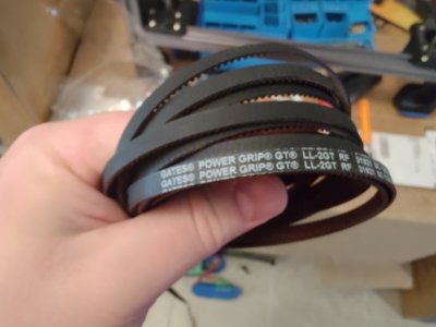
I fired up Steve's 2nd LDO Trident stream and watched him belt up that Trident, and then I did the same thing on mine. Had a little trouble fishing the belts through the A and B motor mounts, but got it in the end... No ABS was used as an idler in the making of this printer.

IMG_20230212_120659541.jpg
Nice.

Everything went pretty well with the belts, and with the toolhead mounts. Trimmed up my belt ends (left enough to pull the belt ends up, out the front, and fold them over under the toolhead piece, in case I need the extra length later, and then went to mount the probe.

That little probe retaining piece (the one that goes on the back of the toolhead mount with the two heat set inserts) was AWOL. We ended up finding it, but not before I mounted the thing with two M3 T-Nuts. :ROFLMAO: I pulled the T-Nuts off, and used the right part once I found it. (it looks like I had it on my cardboard box parts tray and it slid off when I moved stuff to get into the box underneath the printer.)

IMG_20230212_170436611.jpg

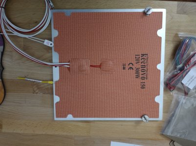
Now I need to figure out the heater on the bed. The way this heater is drilled and tap does not appear to be immediately compatible with the build plate in that the holes for PE and the thermal fuse are covered by the heater. I asked for some advice in the Trident channel on the discord, and was cautioned against piercing or cutting the heater, but they seemed to think nudging it forward may work okay -- I may jump into the West3D channel and see if the folks there have any advice (I bought both parts from them). I think to do it right I'm going to have to get some metric Drills and taps, and I'm not looking forward to doing that... But, my dad is in town, and he grew up on a farm, his professional background is in workholding and machining, and he's helped out in the shop back when he worked for a tool and die/ He knows his way around a tap and should be a good help should it come to that. He's been pretty interested in the build, as he's constantly designing stuff to be run on CNC Mills (big ones) and used to do a lot of injection mold design.

IMG_20230213_083839366.jpg
 
Update 4

Finished up the bed assembly, and installed it. I had to clean out the spherical bearing retention screw holes with the tip of my knife in order to get those little M3 Button Head Screws to thread into the plastic, but other than that, it went together fine.

IMG_20230216_213321004.jpg
Yes, I know the bed frame is crooked. I did that on purpose.

I picked up a M3 tap and a 2.5 mm drill bit and a tap handle. We're going to have to dril and tap the bed. We'll probably handle that this weekend.

I assembled the Z Endstop, also.

IMG_20230216_213337876.jpg
Look Ma! No Screws!

The endstop housing is the stock old-school bring-your-own-switch-and-jst-connector type, and there aren't any screw holes for the board version of the endstop. So I superglued the board to the plastic piece (after testing it first) and installed it. This guy won't be in the printer very long (as I'm going to install Tap when I convert to SB and CW2), so I figured it would be fine for now. I also left one of the grub screws in the pulley so it could hold onto the pin for me when I invert the printer next.

I did not install the Wago mount to the other side, as I'm pretty certain that it did not come in the PIF kit. I'll print one when I'm done and then snap the wagos into it.

In other news, while I was digging through the bag of printed parts for the electronics bay looking for the the Wago mount, I found the rail centering jigs. 🤦‍♂️ BrewWeasel did not forget them after all!
 
Last edited:
Update 5

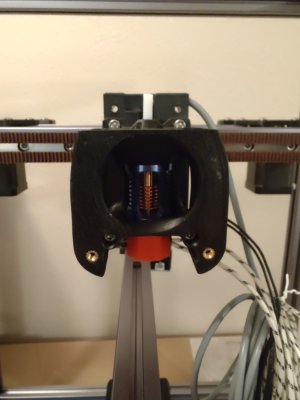
We started the Afterburner assembly. I installed the heater and the thermistor in the Dragon, and then mounted the whole thing into the printed parts. Then, they all went into the printer.

IMG_20230217_224019007.jpg

Here's a wider-angle shot.
IMG_20230217_224005863.jpg

It was getting late, and I didn't want to start the extruder. I started working on the Electronics.

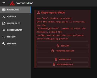
Klipper.JPG

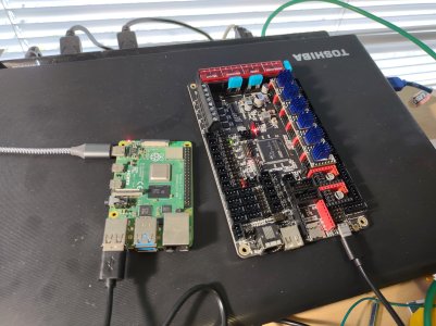
It's time to plug the Octopus in and configure things.
 
Update 6

Started work today with the electronics.

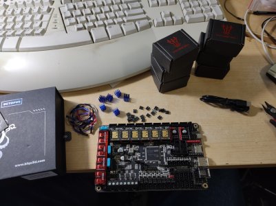
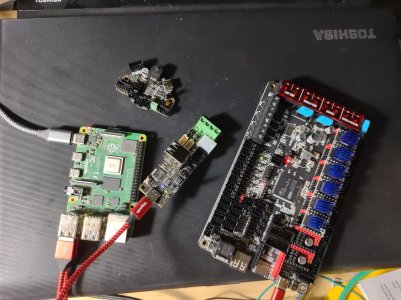
I Installed the TMC2209 drivers and installed Klipper on the Octopus.

IMG_20230219_115928469.jpgIMG_20230219_124945380.jpg

OctopusOnly.JPG
MWAHAHAHAHAHAHA!I

I then went on in the manual and built Clockwork and Afterburner. It went pretty smooth. My biggest issue was mounting clockwork on the printer -- It turned out my PTFE Tube was just a bit too long. I measured it out at the prescribed length, but it was just enough too long that the "B" side M3x20 wouldn't thread into the heatset.

IMG_20230219_163500810.jpg

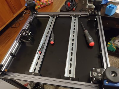
Moving on, it was finally time to put that deck plate in. I ended up pulling the rear Z Motor (Z1), rotating it 180° putting the deck in, and then putting it back where it was. My motors have a little protective flange over the JST connector and that wasn't letting the ACM clear the motor.

I mixed up the deck supports with the zip tie things (I was using the manual on the phone, and didn't really zoom in), the ones I have looked different to the ones in the manual. I figured it out pretty quick.

IMG_20230219_174825692.jpg

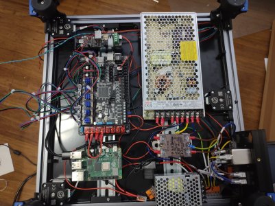
And then I put all of the din rail mounts together. And the power inlet.

IMG_20230219_182529332.jpg

Up Next: Finishing up getting the CANBUS stuff preflashed, and preemptively applying the configuration for sensorless homing (like if I was doing a V0.2).
 
Update 7

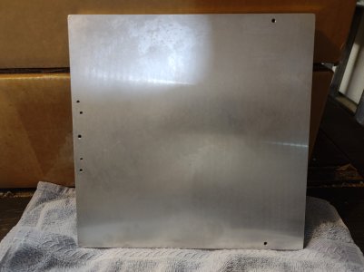
I drilled and tapped the build plate to accomodate the Edge-to-Edge heater. Dad Supervised. :) They're crooked AF, but they fit where we had the heater, so I am good. Plus, most people aren't going to see it anyway.
01 - Build Plate.jpg


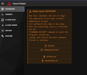
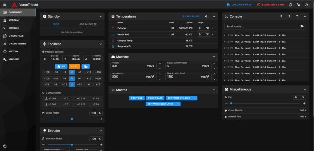
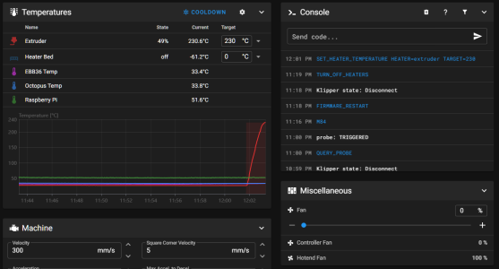
I set the min/max values on the Thermistors and played around in Mainsail for a bit while I had the electronics hooked up on my desk. I'll have to change them back when I get everything connected. I also set the diag Jumpers and adjusted the config for sensorless homing.

While I had everything running on the desk, I flashed the latest firmware on the U2C, and dropped CanBoot on the EBB36. I'll have to finish up putting Klipper on the EBB36 when I have the umbilical completed.
02 - Electronics.jpg

I designed up a mount for putting the EBB36 on the NEMA 42 Motor and printed it on the Flashforge out of the devil's plastic. That'll probably be my first print out of ABS once I get this printer all enclosed. The PETG will start getting creepy after a bit... Of course, I'm going to SB and CW2 pretty quickly after it starts printing, so... maybe it won't be much of a problem.
03 - Toolhead board Mount.jpg
04 - Toolhead Board Mounted.jpg


Apparently, The United States of America has standardized on 2.5mm wide zip ties for its 4" long models, which makes it very difficult to tie off the heater and thermistor wires when Afterburner seems to want a smaller width zip tie. I assume the these zip ties are supposed to be the same zip ties as the V0.2 Sourcing Guide calls for, as the Trident Sourcing Guide doesn't actually call them out at all, and the BOM generated from the configurator just wants "4 inch cable ties". The usual suspects (Home Depot, Lowes, Ace Hardware) only have the 2.5" ties, and I can get them from Amazon, but I have to wait for them... StevenB in the discord suggested that I take the flush cutters and trim the side of the zip tie off and see how that worked.

It worked great.
05 - Zip Tie Hack.jpg
Someone else jumped in after I modified the zip ties and said that they found the super skinny ones at Harbor Freight. Good to know.


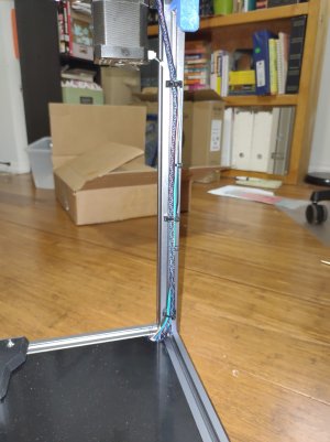
I have the bed (and the Z Endstop) wires run up into what will be the build chamber, as well as the A and B Motor wires. The motor kit I got from DFH has what appears to be PTFE for FEP prewired harnesses for each of the motors, so that's cool. I guess I really didn't need to worry too much about buying the wiring harness. Oh, well.

The standard size American Zip Ties seem to work okay with the twist-in zip tie mounts, so I'm good there.
06 - AB Motor Wires.jpg

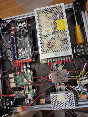
Wiring has commenced. I'm using the white cable ties under the deck because I have more of them.
07 - Electronics Bay.jpg

I think it's kind of funny that whoever made this harness kit for West3D made a neutral jumper instead of a DC ground jumper. I like that it's a heavier gauge though.

I need to run to Lowes or Home Depot or something and get some terminals and a crimper. I have to make some cables for the U2C 24V in, and I'm going to do something different for the 5V side.
 
Last edited:
Update 8

Das Blinkenlights!
IMG_20230226_162806766.jpg
I'm going to make a din mount for those 5V Wagos and get them cleaned up. I fused the 5V because of LED Reasons. I probably don't need it, but it's better to be safe than sorry.

Also: IT HOMES!
VoronTridentHome.JPG
I had the B and A motors swapped because I wasn't paying attention to the instructions. 🤦‍♂️ I found out pretty quickly that they were swapped, because Y homed to the front instead of the back.

Now to make a Canbus Harness, put the Z Chain on, and get the EBB36 into the CAN network and hook up all of the things.
 
Last edited:
Update 9

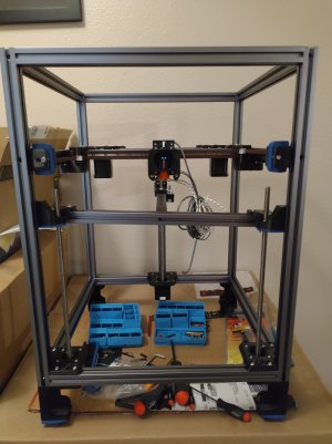
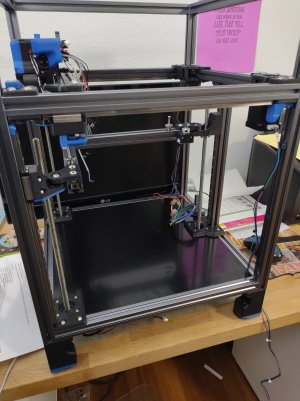
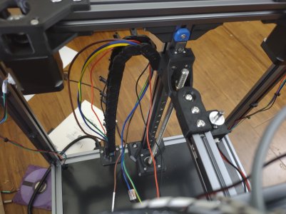
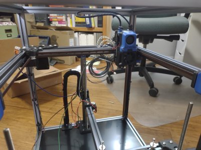
Z Chain is on! Gonna need to pull those wires back, methinks, and trim them up a bit.
IMG_20230228_115124554.jpg

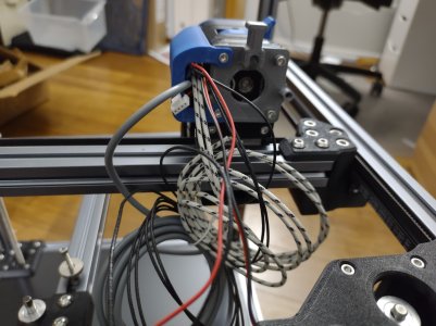
Got the Umbilical built. Did my first crimps (ever) for the toolhead board end, and thanks, I hate it. (I only wasted 3 pins, so I suppose I'm doing well.) I'm trying to decide if the 1/8" (3.175 mm) cable sleeving was too small (it was a PITA to get on there) and if I ever need to buy more if I should go for the 1/4" (6.35 mm) stuff. OTOH, it seems stiff enough with just two 20AWG wires (24V and Ground) and three 22 or 24 AWG wires (a twisted pair for CAN and a spare 24V line for the inductive probe because I didn't feel like splicing into the other one) that I don't think I need to put any "Steel Rope" or Piano Wire in. 🤷‍♂️
Umbilical at zero zero.jpgUmbilical at 250 250.jpg
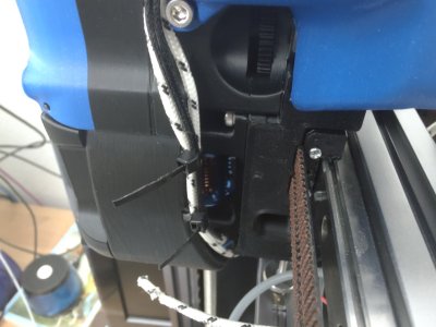
The finished product will end up having a quick-connect on the Stealtburner so I'm just securing things with zip ties for the time being.

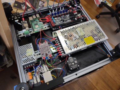
I ended up rearranging some stuff under the hood. I moved the U2C to the other end of the DIN rail (for easier access to the corner where the CAN harness enters the chamber) and shuffled everything around. I used the USB C 90° cables I bought and they all fit pretty well in this arrangement without ingressing into the extrusion area (where there will be, at some point, skirts. I ended up using one of the cables for a direct hook up to the Raspberry Pi for power, and my undervoltage warnings went away. I hacked the USB C end off about 3 inches or so from the connector, soldered some 20AWG wires to the red and black wires, and heat shrank the !@#$ out of it.

You can see the other end of the CAN harness there by the Z2 motor.

You know that stabilizer bracket for the LRS200-24? It's too long. Mine doesn't have that 2nd mounting hole, so I'll need to either find a different STL or alter this one (or make one of my own based on this one).
Under Bed.jpg
I think I'm going to print some of those cable races like what LDO puts in their kits to get these motor wires under control. Zip Ties are only going to cause me heartburn later.
I'm pondering spinning the Z Motors 90° so the cables are going into the area sideways. Not sure yet.

And now, for your moment of cable-dressing pr0n:
Dressed in cable pr0n.jpg


Will he get the other end of the CAN Harness Crimped? Will the CAN network come up? ARE THE CRIMPS GOOD?

Tune in next time for the thrilling conclusion! Same Bat time, same Bat channel!

batman help GIF

 
Update 10

When last we left our Caped Constructor, he was in the midst of crimping the CAN Harness. WAS HE SUCCESSFUL?!


Not to put too fine of a point on it, yes.
1678119487543.png

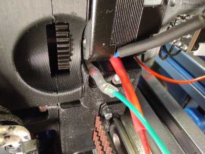
I managed to mangle up one of the CAN crimps on the toolhead end (can't remember if it was high or low -- the green wire anyway) and it broke on me. Need to get some more 2x2 (hands of blue) microfit ends and pins for spares. After fixing that little problem, the CANBUS network came up beautifully, and flashing went very smoothly.
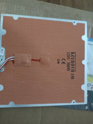
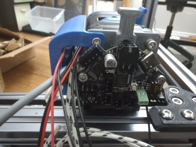
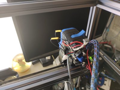
I could not, for the life of me, get the thermistor wires to stay terminated, but I'd had good(ish) luck doing the crimps on the 22 AWG PTFE wire, so I terminated some wires, plugged them in, ran the wires behind the ebb36 board in and up and in, and then soldered them onto the thermistor wires. I had wasted enough pins and ends, and had enough... I was so irritated that I cleaned my bench off so I could solder things together. I still need to shrink the heat shrink down. I'll have to go out to the garage to grab the heat gun.

I don't have the probe done yet, nor the extruder motor, but everything else on the toolhead works. 🎉
Back of Toolhead.jpg
1678122246838.png
In other news, when you have a PT1000 thermistor, set the jumper on the EBB36, and set your pullup_resistor value in Klipper to 2200. There's not a lot of guidance on this in the Docs. Happily, the folks in the can_bus_depot channel in Discord were able to 'splain it to me.

In other other news, I've finally gotten around to putting the heater on the bed. It's a little bit crooked because I wanted to make sure I did not mess up the placement in the back where the ground and the thermal fuse are, so I started there instead of at the front. it's close enough for my purposes. 🤷‍♂️
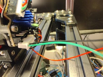
Bed.jpg
 
Last edited:
Update 11

So I moved onto ensuring the extruder motor worked. My DFH Motor Kit came with a pancake motor with a wee little clippy molexy connector on it (sort of like JST and Microfit got together and had a baby), so I used the cable that came with it, and just trimmed down the wires and reterminated the cut end with a JST. Plugged it in, and tested.

Nothing moved.

So I shut it down and tried the thumbwheel on the side of the Afterburner.

It did not turn.

I disassembled the toolhead to the point I could get the Motor off, and discovered that the reason it wasn't turning was becuase I had jacked up the motor when I pulled the screws out of it for the toolhead board mount. So, I pulled all of the screws back out, and then squished the layers of the motors back together and put the screws back in. The motor turned again, and I put it all back together.

BEHOLD. EXTRUSION.
Well, retraction. I had to reverse the pin in the config.

Next up, I've got to jerry-rig the inductive probe. I ran an extra line up from the electronics bay for 24V which needs to be terminated, and I need to make a little harness. Ideally, I'd use microfits for that, but I don't have any, so JSTs it is. It's a bit janky, but It's being replaced pretty swiftly anyway, We'll see how it works. 🤷‍♂️

Also, I need to find my Raspberry Pi Heat Sinks.
 
Last edited:
Update 12

This gif sums up what happened when I attempted to connect up the inductive probe:
star-trek-data.gif


A pre-emptive TL;DR -- through a comedy of errors on my part, the wire coming out of the sensor ended up being far too short. So I had to take the toolhead apart.

Again.

~#~#~#~

[1 hour earlier]

It started out so well, too. Because I don't have any dupont crimps or ends, I decided that since the pin pitch on the probe pins on the EBB36 is the same as the JST connectors I have, I just trimmed off the keying bosses off of the JST and shoved it on there. It's surprisingly secure. (Black for GND, Green for Signal, and the red is coming up from the electronics compartment for 24V). These will be soldered to the pins on a 3 pin JST socket.
Probe Harness.jpg

Initially, I cut the probe's cable longer than it needed to be, and attempted to strip back the outer insulation. I ended up taking the insulation off of the conductors as well. So I trimmed it back further, and ended up doing the same thing. and now it was sticking out past the toolhead by a half inch or so (12-13 mm). (It's possible I'm exaggerating, but at the time it sure felt like a half inch.)

So, I spent a good 10-15 minutes looking for a new probe. This one is one of the cheapy Chinesey PL08N2 Jobbies, and while I can get those on Amazon, I didn't want to wait until next week (or later) to get the NC version. So I ordered the FYSETC Omron which will be here on Saturday. (I looked at maybe buying one from Fabreeko, who is relatively close, geographically speaking, or another one from West3D, but we'd be looking at next week delivery at the earliest, and I'm impatient.)

Then, I realized that I could probably salvage the PL08... So I took apart the toolhead. Again. I didn't cancel my order. Just in case.

By this point, the cable was around 3 inches long, so I just grabbed the outer insulation with my fingers and worked it off of the inner wires. I grabbed some PTFE wire and started stripping, tinning, soldering, and heat-shrinking. When I got to the signal wire, I figured I may as well put the diode in, so I did that. I used fancy transparent shrink on that joint so I could see the diode and not wonder later if it was already installed.
New Probe Wiring.jpg
And then I put the toolhead back together. Again.

Next Steps: 1) Solder the Board harness to the socket. 2) Trim and crimp the wires coming off of the probe. 3) Test. 4) replace the probe if testing does not go well; if testing does go well, return the new probe for a refund.

Also, I gotta remember to turn off the printer before I mess with the EBB36. Last night was the second time I was messing with things and managed to make Klipper angry. 🤷‍♂️
 
Sorry for your mishaps but it does make for some good reading.

Eh. Mishaps are how we learn.

Also, most of mine are self-inflicted... If I'd just have built stock, it wouldn't have been as dramatic. 😁

Also, Also... I'm now very good at taking about Afterburner. :cool:
 
Top