brendanm720
Well-known member
Update 13

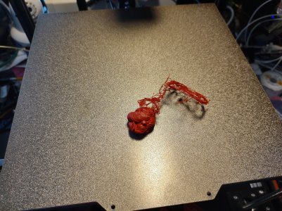
What in the ever-loving !@#$?!
[two days earlier]
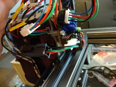
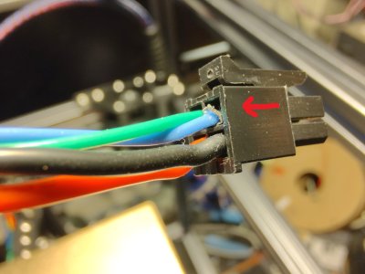
I began work on wiring up the inductive probe. I took a 3 pin JST socket and soldered it to the 24V line, the Ground, and the data wires, and put plug on the wires coming out of the probe. It's not perfect, but it detects my Leatherman, so I guess it works. It seems to work fine in Klipper also, so there's that.
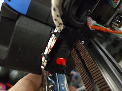
Next, I attached the bed. The Manual calls out M3x16s for attaching the bed, but with this particular bed, we're looking at M3x20s. I ended up stealing one from the Z Endstop pod (I ran out) and replacing it with a M3x30 and a nylock nut on the pod.
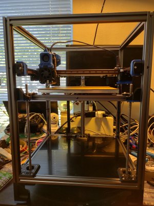
It was then I tried to do a Home All...
...And the cooling ducts went Z-Negative-China. It didn't take me long to figure out why -- or what I thought was why.
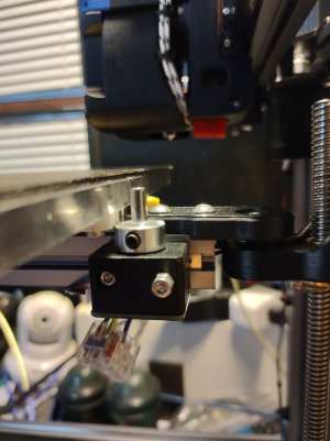
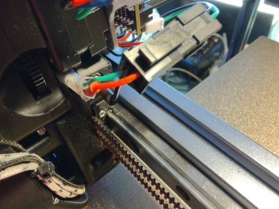
It did take me a bit to figure out a work around. I tried a number of things, and ended up finding that a SHCS 3x30 mm screw was just about the right height (what with the socket head being around 5mm), but wasn't big enough around and didn't always actuate the switch. The M5x30 screws I had on hand are BHCS and are thus still not long enough (button heads are not as tall as socket heads). I need something right around 35mm long, and I just so happened to have some M5x40s.
Time for some "Custom Machining".
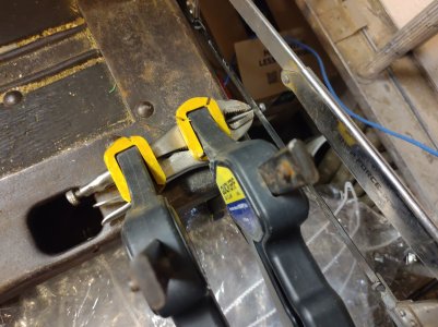
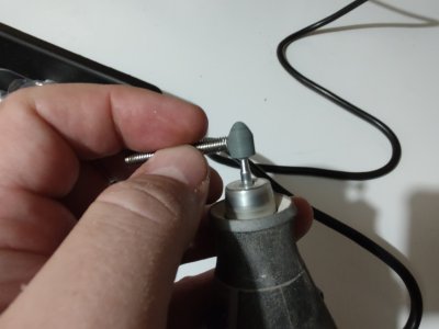
That's Better.
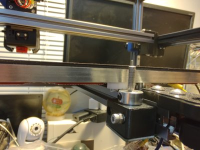
It was about this time I noticed (because the toolhead was now missing the endstop and still going Z-Negative China) that we were homing x, then coming off of the side 15mm (instead of 10) and then homing Y and backing off 5mm... but Klipper seemed to think it was at max travel (250, 250). After a quick question to discord later, it turns out I missed this very important step.

So that fixed things. Mostly.
During troubleshooting, I realized that the printer now thought that the back corner was 250,250... and the nozzle was off the bed. So I changed the max travel # to 255,255, and now we're back in business. 0,0 is right up at the corner of the bed where it's supposed to be, and 250,250 is in the back corner, where it's supposed to be. I did notice that I can't tell the printer to go all the way to the front (past the bed), but I can fix that later, if I feel like it.
I noticed that the nozzle wasn't quite hitting the endstop and instead of changing the settings in the config file like a normal person, I made a new and improved version of the endstop using the spare M5 nuts that came in my BDF Kit.
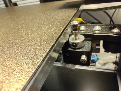
Anyway. I homed the thing about 10 times with no further issue (well, one time the bed was up too high and the gantry was all the way back and the nozzle snagged on the new-and-improved endstop pin and carnage ensued, but that was self-inflicted).
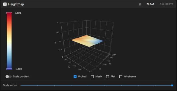
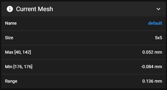
Then I tested Z Tilt. It worked. I did the probe accuracy thing. It was better than the numbers the Voron Pre-Flight checklist said I should be better than.
Then I hot-tightened the nozzle, and put the sock back on.
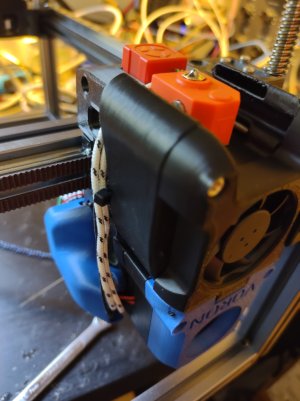
And broke the bottom zip tie loop thingie.
I PID Tuned the bed, and then the nozzle.
I calibrated the Z Height (it was waaaaaay off).
I did NOT calibrate my E-Steps. I too like to live dangerously.
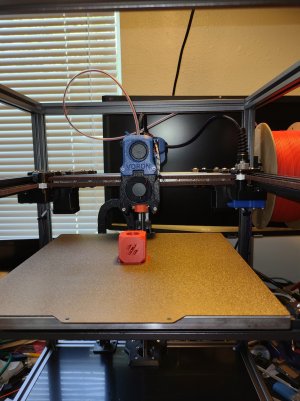
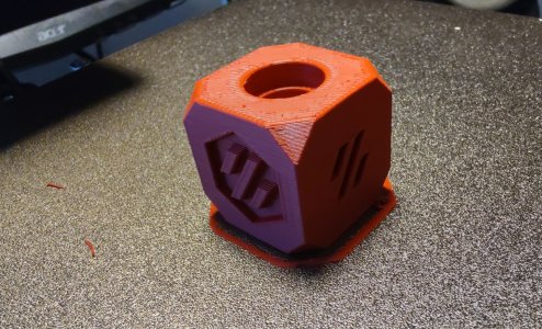
I downloaded SuperSlicer and sliced up the obligatory and ubiquitous Voron Cube (v7). (I did manage to not put a solid top on it, but It's the first time I've used a Slic3r-based slicer, so... )
)
I sent it.
To Be Continued...

What in the ever-loving !@#$?!
[two days earlier]
I began work on wiring up the inductive probe. I took a 3 pin JST socket and soldered it to the 24V line, the Ground, and the data wires, and put plug on the wires coming out of the probe. It's not perfect, but it detects my Leatherman, so I guess it works. It seems to work fine in Klipper also, so there's that.

Next, I attached the bed. The Manual calls out M3x16s for attaching the bed, but with this particular bed, we're looking at M3x20s. I ended up stealing one from the Z Endstop pod (I ran out) and replacing it with a M3x30 and a nylock nut on the pod.

It was then I tried to do a Home All...
...And the cooling ducts went Z-Negative-China. It didn't take me long to figure out why -- or what I thought was why.

It did take me a bit to figure out a work around. I tried a number of things, and ended up finding that a SHCS 3x30 mm screw was just about the right height (what with the socket head being around 5mm), but wasn't big enough around and didn't always actuate the switch. The M5x30 screws I had on hand are BHCS and are thus still not long enough (button heads are not as tall as socket heads). I need something right around 35mm long, and I just so happened to have some M5x40s.
Time for some "Custom Machining".


That's Better.

It was about this time I noticed (because the toolhead was now missing the endstop and still going Z-Negative China) that we were homing x, then coming off of the side 15mm (instead of 10) and then homing Y and backing off 5mm... but Klipper seemed to think it was at max travel (250, 250). After a quick question to discord later, it turns out I missed this very important step.

So that fixed things. Mostly.
During troubleshooting, I realized that the printer now thought that the back corner was 250,250... and the nozzle was off the bed. So I changed the max travel # to 255,255, and now we're back in business. 0,0 is right up at the corner of the bed where it's supposed to be, and 250,250 is in the back corner, where it's supposed to be. I did notice that I can't tell the printer to go all the way to the front (past the bed), but I can fix that later, if I feel like it.
I noticed that the nozzle wasn't quite hitting the endstop and instead of changing the settings in the config file like a normal person, I made a new and improved version of the endstop using the spare M5 nuts that came in my BDF Kit.

Anyway. I homed the thing about 10 times with no further issue (well, one time the bed was up too high and the gantry was all the way back and the nozzle snagged on the new-and-improved endstop pin and carnage ensued, but that was self-inflicted).
Then I tested Z Tilt. It worked. I did the probe accuracy thing. It was better than the numbers the Voron Pre-Flight checklist said I should be better than.
Then I hot-tightened the nozzle, and put the sock back on.

And broke the bottom zip tie loop thingie.
I PID Tuned the bed, and then the nozzle.
I calibrated the Z Height (it was waaaaaay off).
I did NOT calibrate my E-Steps. I too like to live dangerously.
I downloaded SuperSlicer and sliced up the obligatory and ubiquitous Voron Cube (v7). (I did manage to not put a solid top on it, but It's the first time I've used a Slic3r-based slicer, so...
I sent it.
To Be Continued...


