What's new
VORON Design

Register a free account today to become a member! Once signed in, you'll be able to participate on this site by adding your own topics and posts, as well as connect with other members!

Voron 2.4r2 300mm build,question about 0.0 toolhead position

I'm printing right now so can't test, you could try:
Code:
max_power: 1.0 #0.5                       # max speed 100% might be too loud for these fans unless dampened (may change for quieter fans later)...
kick_start_time: 0.5                      # full speed for x to make sure fan spins
shutdown_speed: 1.0                       # if error occurs, keep fat at 100%
stepper: stepper_x, stepper_y, stepper_z  # trigger on stepper or heater 
heater:                                   # From: JamesH[E3v2,MercOne.1+,Micron+] on Discord
idle_timeout: 30                          # keep fan active for x seconds after heater (extruder) is turned off
 
I have tested this and same thing fans turn off only after XYZ drivers are disabled. Klipper is updated but nothing changed.
max_power: 1.0 #0.5 # max speed 100% might be too loud for these fans unless dampened (may change for quieter fans later)...
kick_start_time: 0.5 # full speed for x to make sure fan spins
shutdown_speed: 1.0 # if error occurs, keep fat at 100%
stepper: stepper_x, stepper_y, stepper_z # trigger on stepper or heater
heater: # From: JamesH[E3v2,MercOne.1+,Micron+] on Discord
idle_timeout: 30 # keep fan active for x seconds after heater (extruder) is turned off
Now one thing that i noticed is that my electronic fans are not PWM fans,only 2 wires fans connected to PD12 so as it goes fans can be only on or off,speed of the fans is not adjustable.
 
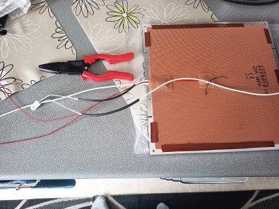
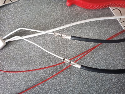
I have some questions about voron bed thermal fuse. What would be correct way to connect thermal fuse to bed wire? Normally when vibrations and heating/cooling cycles are expected soldering wire is not best option so i went with crimping the fuse to harness as it is more resilient to vibrations and bending then solder. I used a dedicated crimping connectors for this job. What do you think is it the way to go?
 

Attachments

  • IMG_20240421_110350.jpg
    IMG_20240421_110350.jpg
    292.6 KB · Views: 3
  • IMG_20240421_110359.jpg
    IMG_20240421_110359.jpg
    444.7 KB · Views: 3
Re fans, it's understandable they don't stop until drivers are disabled, after all they draw current just to hold a position but even so, the code should allow dropping the fan speed.
The sample code appears to suggest this is how things work but in fact the code only works after M84 (Disable Steppers).

There are two occasions where soldering connections is not recommended, the first being close to heater elements as solder joint can weaken is heat cycled, the second is where connections can loosen as a result of vibration. Loose connection especially in high current circuits, introduce hot spots which can melt solder which in turn leads to looser connection, eventually breaks in the circuit will occur. In general any connection subject to vibration or heat should be crimped and where possible dampened...

Crimped connections in circuits that experience vibration should be checked as part of regular maintenance... over the years I have found quire a few, I don't fully trust crimped connections, I much prefer connections where some form of tension is used...
 
Last edited:
You are right,fans needs to be active for the time drivers are in use. I dint notice a reduction of fan speed but on the other hand i didnt pay attention to it. I have to test and report back.
About fuse,some sort of screw terminal would be the best option,but all i have are hi currant din rail connectors that are just too big to be installed behind the bed and bed MTX power connectors that are used to deliver power to the bed heater. I will go with the crimp method and make sure that connections are checked regularly.
 
I went with two (2 pin) Wago 221-412 connectors/claps (supplied with the kit) mounted with printed part and attached to the frame with two M3x8 fasteners/screws (under the bed) for that.

I also bought a few Wago 221-415 (5 pin) Wago connectors as they were inexpensive. I mounted the 5 pin connectors but used a different connector for mains connections in the electronics bay as I had already wired up everything, the 5 pin connectots were mostly spare... Link to other connectors I used

Wago connectors are inexpensive and are highly rated and as the spring clamp always exerts pressure I would choose these over crimping in a pinch, but the jury is out as to which method is best.
 
Last edited:
Hi. Yes my build uses the same wago connectors 221-415 in electronic bay. I totally forgot about wagos.I can get them from local store. (y)
 
Top