What's new
VORON Design

Register a free account today to become a member! Once signed in, you'll be able to participate on this site by adding your own topics and posts, as well as connect with other members!

Voron 2.4r2 300mm build,question about 0.0 toolhead position

Printer Model
Voron 2.4r2
Extruder Type
Clockwork 2
Cooling Type
Stealthburner
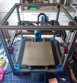
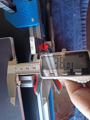
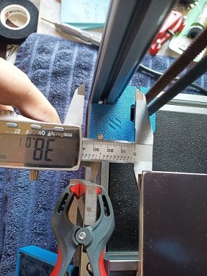
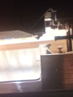
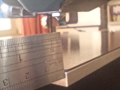
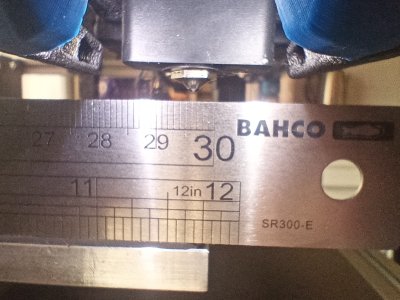
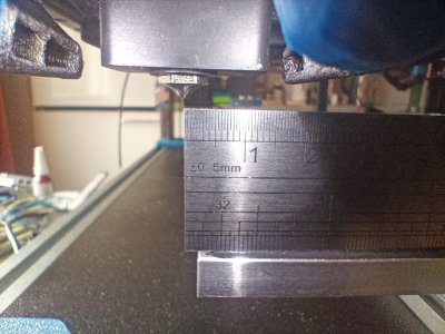
Hi. I was running final check on the motion system and when checking 0.0 position found out that tool head nozzle comes short of the bed corner by 10mm in Y direction when it is at 0.0 position. I would expect that when tool head is moved to left front corner of the bed nozzle would be at the left front corner over the bed. This is not the case. Bed size is 300x300 and bed was assembled as per voron manual. I have confirmed bed and extrusions position is correct. In Y direction when homed i have about 10mm of free space available to move bed and endstop back,so do i just move my bed and z endstop back and configure new position in klipper? I also have about 10mm of possible travel after 0.0 position is triggered so option 2 set max travel distance to 310? What would be the best solution?
 
Double check distance from front of bed to outside front extrusion is 38mm...

BedSpacing2.jpg
 

Attachments

  • BedSpacing1.jpg
    BedSpacing1.jpg
    189 KB · Views: 6
Last edited:
Hi, I double checked again from front of the extrusion to the edge of the bed with caliper 38.01mm. My z endstop is 1.5mm from the edge of the bed. Coult it be that my endstop klipper config is incorect? XY endstop switch location is 300mm?
## Uncomment for 300mm build X
position_endstop: 300
position_max: 300
## Uncomment for 300mm build Y
position_endstop: 300
position_max: 300
 
I didn't use end-stops, I used virtual-endstops (sensor-less) so I'm not familiar but the documented defaults values for 300 are correct.

I would imagine if the rotation_distance was incorrect it could result in travel errors but apart from that I'm lost.
If config values are correct, swap x,y pulleys and see if Y is now corrected, if so, change the other pulley.

Can you post your X and Y sections of the printer.cfg file...

Mine (not using end stops)
Code:
## Y Stepper on MOTOR1 / DRIVER1 (A Motor)
[stepper_y]
step_pin: PG0
dir_pin: PG1
enable_pin: !PF15
rotation_distance: 40
microsteps: 32
full_steps_per_rotation:400  #set to 400 for 0.9 degree stepper
endstop_pin: tmc2209_stepper_y:virtual_endstop
position_min: 0
position_endstop: 300
position_max: 300
homing_speed: 40  #Max 100
homing_retract_dist: 0
homing_positive_dir: true
&
Code:
[tmc2209 stepper_y]
uart_pin: PD11
diag_pin: ^PG9
interpolate: False # True
run_current: 1.0
hold_current: 0.5
sense_resistor: 0.110
stealthchop_threshold: 0
driver_SGTHRS: 140 #your value may differ

Check: rotation_distance, full_steps_per_rotation and possibly microsteps...
 
Last edited:
Hi. I checked pulleys gt2 20 teath on A and B motors are 0.9 degree ,belt tension ok,movement of motion system is smooth. Here is the config for X Y

# X/Y Stepper Settings
#####################################################################

## B Stepper - Left
## Connected to MOTOR_0
## Endstop connected to DIAG_0
[stepper_x]
step_pin: PF13
dir_pin: PF12
enable_pin: !PF14
rotation_distance: 40
microsteps: 32
full_steps_per_rotation:400 #set to 400 for 0.9 degree stepper
endstop_pin: PG6
position_min: 0
##--------------------------------------------------------------------

## Uncomment below for 250mm build
#position_endstop: 250
#position_max: 250

## Uncomment for 300mm build
position_endstop: 300
position_max: 300

## Uncomment for 350mm build
#position_endstop: 350
#position_max: 350

##--------------------------------------------------------------------
homing_speed: 25 #Max 100
homing_retract_dist: 5
homing_positive_dir: true

## Make sure to update below for your relevant driver (2208 or 2209)
[tmc2209 stepper_x]
uart_pin: PC4
interpolate: false
run_current: 0.8
sense_resistor: 0.110
stealthchop_threshold: 0

## A Stepper - Right
## Connected to MOTOR_1
## Endstop connected to DIAG_1
[stepper_y]
step_pin: PG0
dir_pin: PG1
enable_pin: !PF15
rotation_distance: 40
microsteps: 32
full_steps_per_rotation:400 #set to 400 for 0.9 degree stepper
endstop_pin: PG9
position_min: 0
##--------------------------------------------------------------------

## Uncomment for 250mm build
#position_endstop: 250
#position_max: 250

## Uncomment for 300mm build
position_endstop: 300
position_max: 300

## Uncomment for 350mm build
#position_endstop: 350
#position_max: 350

##--------------------------------------------------------------------
homing_speed: 25 #Max 100
homing_retract_dist: 5
homing_positive_dir: true

## Make sure to update below for your relevant driver (2208 or 2209)
[tmc2209 stepper_y]
uart_pin: PD11
interpolate: false
run_current: 0.8
sense_resistor: 0.110
stealthchop_threshold: 0

#####################################################################
 
Looks fine, I did a bit of searching and it appears other have had to modify the position_endstop to correct things
For [stepper_y] try:
Code:
position_min: 0
position_endstop: 310   # for 300x300 build
position_max: 310       # for 300x300 build

What settings have you got for home_xy_position?
 
Last edited:
Looks fine, I did a bit of searching and it appears other have had to modify the position_endstop to correct things
For [stepper_y] try:
Code:
position_min: 0
position_endstop: 310   # for 300x300 build
position_max: 310       # for 300x300 build

What settings have you got for home_xy_position?
Hi. X-Y position for endstop is max: 300. Bed size is 300x300.When checking things came to same conclusion that endstop location cant be max 300 when bed is 300mm and gantry is moving past right back bed corner to trigger endstop. At best Y travel max should be close to 310. I will test over weekend and report back.
 
Just got back from work and couldn't wait until Saturday to test. With endtop location Y:310, 0.0 position ,X gantry is just about contacting front tensioners mounts so I set the endstop Y to 308 mm and toolhead nozzle is now 0,9mm over the front edge of the bed.
Moving the toolhead to Y:300mm position nozzle is off the bed by the same amount 0.9mm.. It looks like bed location should be 39mm from the front extrusion,but manual states 38,00mm
 
Home the gantry and measure the tip of the nozzle to front, back and left, right, in theory they should be equal, in practice I would expect slight differences...

These resulting measurements should tell us if the actual bed is centered but a little adjustment to the bed might be required...

Just checked mine, left 151, right 153, front 144, back 161 mm...
My bed is actually 305mm x 305mm and I don't print that close to the edge, the Y error (7mm / 2) = 3.5mm is within limits.

I would have moved the bed if the left vs right or front vs back was greater than 10mm
 
Last edited:
I homed all axis and done some tweaking,checked all corners,bed positions and so on. Happy to inform that after tweaking software,bed,endstop got Y at correct position,only to discover that my X axis is at 300 still over the bed by 3.5mm . Im thinking that my pcb XY switch is that much off as components are surface mount soldered. Learning all the time as Klipper is a new experience,normally Marlin is what I'm familiar with.
 

Attachments

  • Bed position front right.jpg
    Bed position front right.jpg
    84.7 KB · Views: 4
  • Bed position front left.jpg
    Bed position front left.jpg
    111.8 KB · Views: 4
  • Bed mounting extrusions right side front corner.jpg
    Bed mounting extrusions right side front corner.jpg
    93.7 KB · Views: 4
  • Bed mounting extrusions right back corner.jpg
    Bed mounting extrusions right back corner.jpg
    114.3 KB · Views: 3
  • Bed mounting extrusions left front corner.jpg
    Bed mounting extrusions left front corner.jpg
    109 KB · Views: 4
  • Bed mounting extrusions left back corner.jpg
    Bed mounting extrusions left back corner.jpg
    112.8 KB · Views: 3
  • Y axis 300.00 position (ok).jpg
    Y axis 300.00 position (ok).jpg
    434.5 KB · Views: 2
  • Y axis 0.00 position (ok).jpg
    Y axis 0.00 position (ok).jpg
    490.5 KB · Views: 2
  • X axis 300.00 position.jpg
    X axis 300.00 position.jpg
    646.9 KB · Views: 2
  • X axis 0.0 position.jpg
    X axis 0.0 position.jpg
    895.9 KB · Views: 2
Hi and thanks for the help in advance.
Update for X :0.00 position issue. I found out that my X gantry X-Y limit switch is not correct size. X limit switch position is off by 1.5mm. PCB itself should be 51,5mm in lenght with additional 6mm X microswith body and that would be total 57,5mm. However my pcb including switch is 1.5 mm longer and this is changing position of the toolhead by 1.5 mm when X endstop is triggered. I reprinted mount however old and new printed part is the same size with measures wide 31.35, length 58.05, height 14mm . Luckily i don't print on edge of the build plate :cool: 
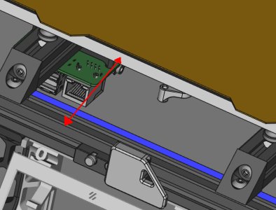
It looks like its desoldering time for the old switch. :)
 
Last edited:
Making progress... down the road you could try sensor-less homing (2209's), it should provide a few more mm's on both X & Y, it also simplifies wiring...
 
Last edited:
Making progress... down the road you could try sensor-less homing (2209's), it should provide a few more mm's on both X & Y, it also simplifies wiring...

You are right,my electronic bay is full of wiring,as much as i like mechanical switches after looking at the amount of wiring in my electronic bay started to think CAN . My Voron has CNC parts so to use sensor-less i need to replace at least 1 Z joint to be able to add magnet right? For CAN was looking at EBB SB2209 and SB2240 and SB2209 has some issues SB2240 seems to work better.
However first need to get my Voron to run like a Swiss clock and then when all testing is done and posible hardware and software glitches are removed i can start with CAN.

By the way im using LDO 1.8 degree motors for Z ldo 42STH48-20004AC, extruder ldo 36STH20-1000AHG (VRN), AB motors 42STH48-20004MAH (VRN) A/B motors are hi temp motors 0.9 degree.
What current can be set for this. At the moment its Voron stock settings for current.
 
Last edited:
That's the best approach, get it to work flawlessly first, then tinker...
For currents, I choose run_current: 0.9, hold_current: 0.5 but I upped run_current to 1.0 recently to see if there was any difference but didn't notice any...

BTW, I built with LDO Kit and (chaoticlab all metal CNC parts including X and Y tensioners and Tap), I also added EBB SB2209 CAN (RP2040) CANBus.

Have a look at my build, it's a bit scattered but a complete Metal Build
 
Last edited:
Nice CNC build. My build was self sourced,build based on Voron/LDO manual. Thanks to Jason from LDO i got my hands on quality stuff, ldo hi temp motors,frame and stainless steel rails .XYZ tensioners came from chaoticlabs, only thing is that chaoticlabs cnc parts are red,blue color would be better. Bed and panels are from lector.com. Z motors are ABS but internal components are custom, black anodized wider pulleys,80T gears are custom made cnc with reduced weight. Gates belts. AB motor brackets and X joints are from Aliexpress, but X joints are modified to accept Voron spec geared pulleys instead of bearing stacks . Electronics Octopus board 429,Klipper touchscreen,UHF Phaetus hotend,PSU meanwell LRS350 and meanwell 5V psu for rpi. Still waiting install ,titanium backers,chamber led lights,klipper extension board.
Decided to do build this way to make sure to get good quality components. Luckily got all the stuff 2023 ,but shipping was expensive. I don't think that in 2024 building from self sourced parts is a thing to do as you can get good quality kits from LDO for less money. However i like my Voron,there is something fulfilling when you build it yourself,you learn a lot of new things and you know your machine from top to bottom.:) Klipper seems hard to master but it has futures that Marlin doesn't. Just be able to make any change in printer.cfg without needing to re flash control board is a great thing. About klipper extension board,is there a way to control electronics fans via klipper as my electronics Sunon fans are loud. Fans turn on at 100% when gantry starts moving,but after all XYZ movement is stopped fans stay on for long time and then turns off. I could not find any setting to control at least fan speed and time duration how long fan is on when there is no movement on printer?
 

Attachments

  • IMG_20240506_164934.jpg
    IMG_20240506_164934.jpg
    290.4 KB · Views: 2
Last edited:
The setting for turning fans off after x time is idle_timeout, but not sure if it is available any fan instance other than controller_fan...
As an example I use:
Code:
[controller_fan Motors_Fan]
pin: PD15                                 #
max_power: 1.0 #0.5                       # max speed 100% might be too loud for these fans unless dampened (may change for quieter fans later)...
kick_start_time: 0.5                      # full speed for x seconds to make sure fan spins
shutdown_speed: 1.0                       # if error occurs, keep fat at 100%
stepper: stepper_x, stepper_y, stepper_z  # trigger on stepper or heater, set to trigger on stepper
idle_timeout: 30                          # keep fan active for x seconds after heater (extruder) is turned off
to control the skirt fans, it activates on any x/y stepper movement. The fans should stop after 30 seconds when movement stops.

I will build another but with all the spares I have, including a 400x400x400mm cube frame I build years back, it will be self sourced...

Klipper was one of the major deciding factors for me, I first installed it on my ender 3 and was sold with the results, the quad gantry leveling was also a major positive factor and Tap made my mind up. I have to admit the build was expensive when compared to off the shelf printers like my CR10S Pro. The CNC parts added to the expense but also the quality of the final build, I'm not regretting the cost, I love to build things so why not build the best...
Klipper is a way to go . Thanks for posting the fan configuration ,I have to test it right away to see if there is any change to the operation of the fans.
Just checked my printer.cfg and there is this configuration
## Controller fan - FAN2
[controller_fan controller_fan]
pin: PD12
kick_start_time: 0.5
heater: heater_bed? Is this input to trigger fans on bed heating Per manual electronics fans are connected to FAN2 PD12 pin
So I removed entry heater: heater_bed and added
max_power: 1.0 #0.5
kick_start_time: 0.5
shutdown_speed: 1.0
stepper: stepper_x, stepper_y, stepper_z
idle_timeout: 30
However fans are running way over 30 sec,strange.Hotend and bed are off,temp.sensors reports 24C but electronics bay fans still running 100%. Looking at the mainsail dashboard controller fan is at 100% for the last 10 minutes. Adjustment slider to reduce speed not availible.Fans will turn off if klipper firmware is rebooted. Hmm..well i have to add this to the check list.
 
Last edited:
I have noticed that too, I tend to home all and wait 30 seconds before the fans stop... It's almost like a specific action is required before timer times out...
I'm guessing it kilpper firmware issue, I'm hoping it's fixed in the future as that is what the stated action should be...

Been on Discord, there's a suggestion to add heater, will test later...
 
Last edited:
Tested some more and yes fans will turn off after 30 sec every time if the motors are disabled. It doesn't seems to be differences between how cooling fans are activated, or duration time, same behavior with heter_bed,heter_extruder. Well we cant have it all :cool:
 
Top