What's new
VORON Design

Register a free account today to become a member! Once signed in, you'll be able to participate on this site by adding your own topics and posts, as well as connect with other members!

Voron V0.2 Formbot kit

ChrisA

Well-known member

Introduction.​


My current printer is an Anet A6 bought as a kit in perhaps 2016. It is an i3 clone with a laser cut acrylic frame. The first thing I did was print some braces to reinforce the frame and then I printed more that allow the printer to be screwed down to a workbench. With the printer firmly now part of a built-in bench it does not move at all and does acceptable work in PLA. My interest in 3D printing comes from my "real" interest in robotics. I am working on version 2.0 of a small quadruped "dog" robot.

Professionally I worked as an engineer in the defense aerospace industry here in Southern California, doing mostly software although I have some formal education in electrical engineering. But mostly I wrote software related to missiles, radars, rockets, and communications. I was able to retire early and had a short second career teaching high school science. Now I am really retired. I have time to work on these printers while trying to ride a road bicycle 100+ miles a week (that's the goal) and spend at least four weeks on the trail in the Serrias (that's the goal.)

My initial plan was to build a V2.4 but I want it customized to print at least two materials. That means IDEX, ERCF or the new "Tap Changer". All of these are not yet 100% mature and I also want a smaller printer that does not take 40 minutes to come up to temperature and will fit on my desk. 120 mm cubed is enough space to make most of my robot parts and also all of the Voron v2.4 parts. I will use the V0 to build a customized V2 next year.

There are already so many of these build logs online. So why do one more? I hope to address things that others don't

Log, Feb 7, 2024​


I have two boxes of parts from Formbot. The parts are all of excellent quality. I see no reason to spend more on some other reseller's kit.

1) Electronics are the BTT Pi3 cone and a "pico" MCU board. Both seem well matched to a V0 printer. There is a small V0 display which is good enough as a status display and for very occasional use. It looks and works just like the one in my Anet A6 printer. I almost never use it. I would get one of the larger touch-screen displays if I planned to use the directly attached screen.

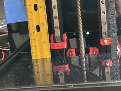
2) The mechanical kit uses Moon's motors and a good quality Chinese linear stainless steel rail. One is a Z1 preloaded for use on X axis. It is easy to tell it from the non-preloaded rails. There were oiled but I need to grease them. I think you'd have to spend a lot to get slightly better rails.

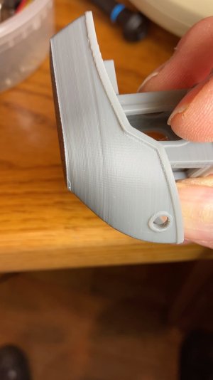
3) Formbot claims to use ABS-GL filament (ABS with 10% chopped glass fiber) in their printed parts. Yes, their parts are different and, I think better. The plastic is a dull sheen and sparkles in the light. layer lines are visible only if you look close, dimensions seem to be spot-on. They look better than many photos of self-printed parted I've seen online. They are also more rigid than plain ABS. For $60 you get a lot of parts. After this V0 is built it will be a challenge to tune my printer to make parts this nice. The cosmetics of these parts are "mat with sparkles" and not the shiny semi-gloss of other ABS parts. As a quiet statement, not to complain about tiny imperfections they include a full sheet of #500 wet/dry sandpaper. The parts fit with no sanding but all 3D-printed parts can be improved with sanding. There are some rough areas that are hard to see but can be found with my finger. Sanding will remove these.

4) panels are all 3mm clear PC or slightly thicker aluminum composite. This is an upgrade from the black PC. At least I think it might be.

STATUS, What is built...​


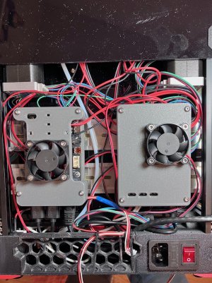
I am doing this backward. Most people leave wiring and software setup until the end but I started there. I have the Meanwell power supply AC mains power cable and switch and the Pi3 clone and MCU and display all screwed down on a pine board and running. Klipper is running and mainsail and octopi. I was able to upgrade the OS on the Pi to Debian "Bookworm". The heaters are left disconnected. I tried running a print using the Mainsail interface but it failed because Klipper noticed the heater temperature was not moving. Next, I will install a webcam and experiment with other kinds of cameras.


What I have learned so far.​


1) The BTT Pi3 clone is well suited for its intended use case and has connecters the standard Pi lacks. But I can't get a "standard" version of Ubuntu Linux to boot. BTT's image loads on the SD card and boots but that image is based on the older "Bullseye" Debian. I was able to upgrade in place to Bookworm. I suspect I could get Ubuntu to work if I made a custom kernel with whatever mods BTT did. I have not looked into it yet. But it seems this is NOT is perfect Pi3 clone. It works and maybe even works better than a real Pi3. It's running Bookword as I type with Klipper, Mainsail Fluid and Octopi all installed. about 8GB of the 16GBSD card are used. The Pi3 has 1GB of RAM and about half is used with everything I installed running at the same time.

2) The content and quality of these kits change fast with time. If you see a 6-month-old YouTuber doing an unboxing of a kit, you can ignore it as "outdated". Most of what I found in this kit differed from what I saw on YouTube and that was a Good Thing.

3) It used to be that if you ordered an upgraded hot end from Formbot they would upcharge you for it and send it in a separate smaller package. So you would end up with two hot-ends, the default V6 and whichever upgrade you paid for. But now they place the upgrade in the main box and remove the V6, so you end up with only one hot end. They also were able to reduce the price of the upgrade. I paid $40 for a Pheatius Dragon Standard Flow.

I have photos and will post a few "soon".
 
Oh my, one of those semi-notorious Avnet printers as the previous printer!

I have a few Pi's already so I am figuring that I'll use a real Pi, primarily because then I won't need to mess around with my Ansible scripts that I use to keep them provisioned. And I looked at the included Sandisk card and for complicated reasons that I won't go into, while I could potentially do some checking to see if it's a "real" one, I'm not going to and use a Samsung high endurance card I've got sitting around. And yah, I guess when I get there I'll probably try to run at least some parts of the complete stack not on the Pi but on my Intel NUC. Right now I'm managing people but ... I work in tech, LOL.

And be warned ahead of time, since we're probably on roughly the same vintage of kids, that it doesn't seem to have the 3D printed stuff from the tools directory. On the bright side for those, you almost certainly can print them on your firestarter with no issues because they aren't complicated parts and yah you can sandpaper them if they ended up out of true.

I've got both a "real" RPi3+ and the BTT version on my desk. I keep them running 24x7. The BTT Pi has a BTT "pico" MCU attached and the other has a BTT Octopus Pro (H723) attached. Both are running the same Klipper and the full stack of associated web interfaces. In real-life testing, I don't soo much difference.

The biggest difference is the BTT Pi can be powered directly from 24 Volts but I am not using that feature. I'm powering it from the Pico.

You are right about missing tools. I printed them myself. The rail-centering tool is useful. The other is only marginally useful, I can measure pully to motor distance with calipers.
 
I bought an LED strip from Amazon to play with and decide if I wanted to use it in my printers. Yes. They are better than I expected.

$25 from Amazon https://www.amazon.com/dp/B079ZWR5SZ

These are 5-volt RGBW LEDs. The white is blindingly bright, and it does RGB colors also. There are 144 large 5mm square LEDS per meter. For the V0.2 printer. I will cut these into three or four 150 mm long strips with 20 LEDs per strip. I doubt I will ever see the need to run the white LEDS more than about 30% brightness. The goal is a shadow-free video so I want lighting from every direction.

How bright? I don't have the means to measure it but it seems as if the entire strip if set to 100% is about as bright as three standard LED lightbulbs. These LED strips could be used for functional lighting in a kitchen or bath.

The next step is finding a way to power them. I doubt the Pico board has enough 5V power to run the lights at 100%. I'll likely use a 24v-->5v converter. I have time to sort this out as the printer is not finished, waiting on parts from China.

I plan to design and print a holder to attach this LED strip to the underside of a 1515 rail.
 
Looks like I mismeasured. The z-stop is a little too high, about 12mm higher than it should be. I edited the config file to change the z-endstop location from 120 to 108. Someday I will lower the rails. likey when I get around to upgrading them. The rails su[plied by Formbot were "OK" but perfect. One was "z1" preloaded and used for the X axis. I sorted the other four and used the best two for the Y-axis. The z-pair has a few tiny rough spots that will not impact print quality.

With the Kirigami bed frame, the rails were rough because the frame is not perfectly flat and tightening the screws down preloads the rails. the Fysect cnc bedframe solves this and the rails now are near perfect. The bed is very stiff.
 

Attachments

  • 456F453E-7F8A-4D06-92DC-2602ADD480E3_1_105_c.jpeg
    456F453E-7F8A-4D06-92DC-2602ADD480E3_1_105_c.jpeg
    205.6 KB · Views: 17
It works, almost. I completed enough of the printer to print a test Benchy in PLA. I used all the default settings in Cura and the "stock" printer config file from the Voron GitHub. I used the paper test to manually level the bed and then just printed a Benchy. It was going well until it got to the roof when the bed adhesion failed and the Benchy fell over.

The attached video is the first attempt to print with ZERO tuning or adjustments.
 

Attachments

  • D99218D5-46BF-49C4-9053-0EC8F58B1BD1_1_105_c.jpeg
    D99218D5-46BF-49C4-9053-0EC8F58B1BD1_1_105_c.jpeg
    110.8 KB · Views: 10
144 RGBW Neopixel strip running on Voron V0.2

I used to Octopus board to learn how to configure the Neopixel strip. Then I moved the strip to the working V0.2 printer's SKR Pico board then the LEDS stopped working. A look at the MCU schematics shows the Octopus Pro level shifts the Data Out to 5-volt logic. The Pico MCU simply connects the RP20450 pin with no buffering. This is wrong. At best this is unreliable. I built a level shifter from some parts I had. It works. Next, I will need to make a compact and reliable level shifter.

The video shows the LED working connected to a working V0.2 with a 2-meter cable going to a prototype board and then to the 144 LED strip.

This strip can draw a full 50 Watts if you turn on every LED to 100%. So I am going to have to never do that, or find room in the printer for another power supply.


193B29A6-4231-4A1D-BC03-73380D781092_1_102_o.jpeg
T
 
Last edited:
The standard Voron V0.2 mounts the two PCBs (Pi3 and MCU) using a psudo-DIN rail setup. I did not like this and also wanted more cooling. So I bought a couple aluminum DID rails and made to boxes with fans. The cooling is very effective. The Pi3, even at 100% CPU stays at 38C with the fan never more than 50%. I'm using a 5-volt 4010 fan. The MCU uses a 24-volt fan at about 50% speed. Tamp stays in mid 30's

I plan to not use the rear PC panel. I will print something that has the same style as the skirts to cover the mid section where the fans are.
 

Attachments

  • IMG_1283.jpeg
    IMG_1283.jpeg
    477.5 KB · Views: 10
Top