What's new
VORON Design

Register a free account today to become a member! Once signed in, you'll be able to participate on this site by adding your own topics and posts, as well as connect with other members!

Solved Y better than X????

Driftrotor

Member
Printer Model
V0.2
ok, so after sorting out my dads V0.1 i finally got round to building my V0.2.
the build went really nice with no issues.
after some tuning she prints really well and it was time to start ramping up the performance.
resonance tests came back and i was really surprised as my Y axis is more than double what my X axis is.
i have to say that i thought it would be the other way round giving that the gantry is quite heavy and thus would have a slower acceleration value.
but i will take 15k, i just need to find whats causing the X to be so low?

things i have checked so far;

belt tension
gantry
rails
tool head (complete)
frame (fixing points)
top hat and front door (on and off)
side panels (on and off)
rear panel and din rail (on and off)
skirts and feet
kirigami bed and bed plate
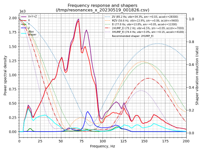
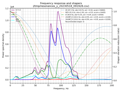
shaper_calibrate_x.pngshaper_calibrate_y-1.png

so im a bit stuck really on what to look at next?
is there a way to improve it?
or is this my machine and this is what i have?

thanx in advance.
 
I am no IS expert, but looking at what might "cause" the differences.

How is the accelerometer attached?
Have you tried an IS tower instead of using the accelerometer?

I think those speeds look pretty good. Also, you can't always go by the recommended settings, sometimes you have to test them to see if some other settings work better. I think someone has a few videos on this...Chris's Basement I think. Found it
 
thanx for your replay, i know this one might be tricky to improve on.
i have tried mounting it on both the back of the strain relief and the tool head itself and both produced almost identical results.
i used the same mount to do my dads v0.1 and he got some really nice results (18k for X and 12k for Y) so i set him up for 10K to keep it sweet.
i was just slightly confused as to why my X axis was so much lower than my Y is it is normally the other way round.
i can confirm though that anything greater than 8k and i get bad ringing on my X axis movements.
i know 7k is still quite good but i get 6k on my ender 3 v2 (modified) so was hoping for somthing similar to what my dad got.

i will have a look at what chris has to offer on his video though as i might have miss a trick or two.

i find that using the adxl345 sensor quite useful as it can help see if you have bad resonance in the frame and at what frequencies. i just have not seen this type before so not sure what to amke of it to be honest. i did discover that i had my AB motors a little on the high side for run current so might run another test to see if this has made any difference. (unlikely i know)
i'm hoping that i can find the main cause of why my printer has a lot of resonance in it as it is quite a high spec as half was self sourced with most of the goodies.

if i find anything i will report back with my findings

again thanx for your input it is most helpful
 
after many hours pouring over the frame, gantry, rebuilding my tool head etc I can say I have tracked down the root cause of the strange resonances.
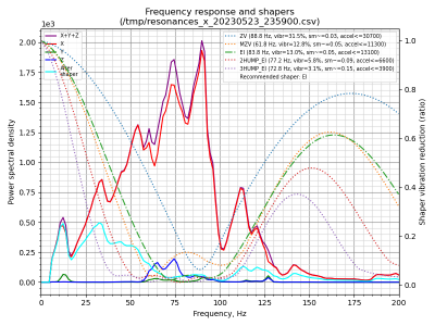
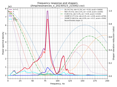
here is a before and after shot of my adxl345 results.

shaper_calibrate_x.pngshaper_calibrate_x-11.png

drum roll please....
it was the umbilical pcb and printed part fixed to the two motor blocks causing some sort of weird resonance / ringing over a wide frequency range and interfering with the machine.
I'm testing using some of the panel gasket fixed to it to see if I can mitigate what is happening.

I'm curious if anyone else has / is experiencing similar issues, but is not aware it is happening?

but I'm happy knowing that I wasn't barking up the wrong tree and that my results are much better, especially with the vibration reduction down to 1%
 
WOW, that is awesome that you found it. Can you share some pics of how it was vs how it is now?
 
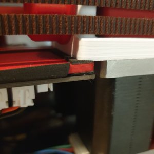
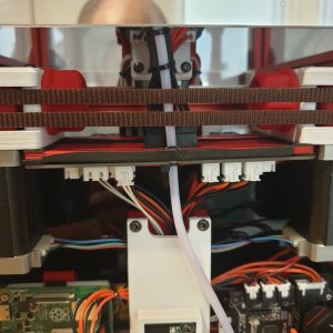
Unfortunately I don't seem to have a before picture of that area, but I have got a pic of what I did to mitigate what was happening on my machine.

16849731971624924326108445167564.jpg


1684973267346435165486442479164.jpg

I have 1 layer between the motor blocks and the printed plate and 2 layers between the printed plate and the pcb of the umbilical.
Before it was just stacked and fixed in place.
One of the main culprits with this seems to be my connector that connects on to the main pcb. If I hold it while running the resonance test it further reduces the resonance from 80 - 105 Hz and I get a better result and just over 15k for the X axis.
I might have a go at creating some type of retaining clip that holds it firmly in place and see if that reaps better results.
But for now I'm much happier with how its running.
 
Top