What's new
VORON Design

Register a free account today to become a member! Once signed in, you'll be able to participate on this site by adding your own topics and posts, as well as connect with other members!

160mm Salad Fork Build Log (DFH kit)

just regular nuts in the 1515 for your backers? nice build btw!
Thank you! Yes, regular M3 nuts and M3x6 BHCS for the backers. These would be nicer with a FHCS in there, as there is already a recess in them for that, but the kit didn't come with those and I don't have enough spares in my inventory either. So BHCS it is, still looks good enough for now.

I may splurge at some point in the future and get anodized titanium screws to go in there, make them blue to match the printer primary color...
 
Yeri,

Congrats on the design and build. I have a Honey Badger kit on order for my 5th Voron build. Debating on converting my v1.8 over to trident. Need to figure out what parts I need for the conversion. When I saw the salad fork, I knew I had to build it. My V1.8 is my workhorse printer. The 160mm build is a nice compromise. My V0 is my go to small parts printer. Soon to add the Salad fork to that list.

Thanks again
 
Z motors attached! First bit of color on the frame! I oriented the steppers so that the wires on the front two point toward the center, and the rear one points left. This is because the AC inlet is on the right, and the less other wires going that way the better. Also because the bed wiring comes down on the left side, so this allows for a little better wire management in the future
 

Attachments

  • IMG_1537 Large.jpeg
    IMG_1537 Large.jpeg
    258.7 KB · Views: 50
When you realize you forgot to print some parts... Good thing I've got a handy salad fork available :)

Also no fear with a lot of small parts!
 

Attachments

  • IMG_1538 Large.jpeg
    IMG_1538 Large.jpeg
    206.7 KB · Views: 53
Got the Z motion, motors and idlers all built. Starting to look like a printer!

I included a detail photo of the rear Z extrusion, this shows how it's intended to look. It does not center on the horizontal extrusion above it, and there should be about a 1mm gap between the two as well. Hopefully this clears up a common question when building a SF or Trident.

Also a salad fork-specific build tip. Doing the motor mounts is a pain with those bearing stacks, what I do to make it easier is to loosen the screws holding the top part in place to give it a few mm of play, then turn the printer upside-down. You can then insert the M3x25 screw partially coming up from below, and build the bearing stacks as you go. Unfortunately I haven't found a similar trick with the front idlers, those require a steady hand.

But now the worst part of physical assembly is done, next up is X axis and toolhead. I'm really liking the way these colors are working, and the white frame is very nice in person even if the camera doesn't show it well.
 

Attachments

  • IMG_1545 Large.jpeg
    IMG_1545 Large.jpeg
    273.1 KB · Views: 46
  • IMG_1544 Large.jpeg
    IMG_1544 Large.jpeg
    162.3 KB · Views: 47
Build is still progressing, been on vacation so it paused a bit. Working on the toolhead, but need to order a fan since I will be putting mini-sb on it instead of mini-ab. Once that gets in I’ll get that all sorted out.

In the mean time, belts have been run, and I decided this one will use boop. I’ve got some new revisions I need to print for that and then we should be good to go for building!

I am also going to use the dropeffect xg on this, it looks like it will fit very nicely
 
Post-holiday progress pics

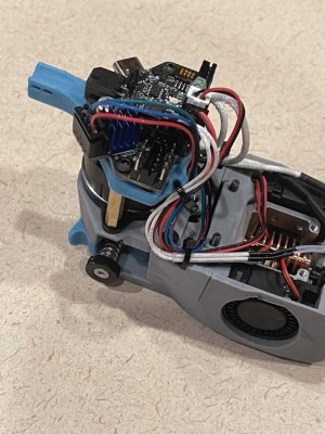
Got the towhead put together, this is a stealth burner of course :)

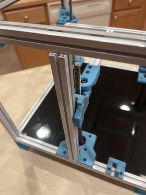
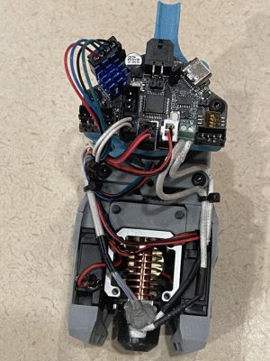
I ran into an issue with the DropEffect XG hotted though, the thermistor is secured in a little brass support with some form of ceramic compound, but mine completely disintegrated. I saw a bunch of bare copper wire in mine as well, so I replaced it with a regular glass bead thermistor I had handy, and used a bunch of high-temp JB-Weld to attempt to hold it in place. This didn't work, as soon as I was done with this photo and went to mount the toolhead it popped out of the brass retainer

I'm trying a different approach now, will know in another 24 hours or so if it holds, if not then I have to keep looking for ways to get this to work. I'd just order a replacement part for this, but can't find anything other than full hotend packages, and not going to do that when all I need is a new thermistor assembly

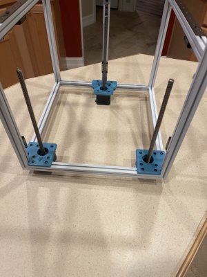
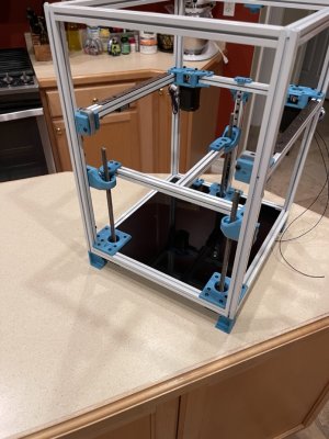
In other news, the printer is fully belted, de-racked, and looking good, just waiting on the toolhead, then it's bed install and wiring time!
 

Attachments

  • IMG_1583 Large.jpeg
    IMG_1583 Large.jpeg
    293.8 KB · Views: 37
  • IMG_1584 Large.jpeg
    IMG_1584 Large.jpeg
    281.1 KB · Views: 35
I have rolls of aircraft safety wire, .5 and .8mm diameter, stainless steel. This makes for a good way to secure things in a hot environment. If your compound process fails, this might be the answer.
 
Wrote an email to the support address listed in the phaetus site, that bounced immediately. Not super impressed with that.

My last attempt at a fix didn’t stay, so I will use some wire to strap this thing into place
 
Top