What's new
VORON Design

Register a free account today to become a member! Once signed in, you'll be able to participate on this site by adding your own topics and posts, as well as connect with other members!

Question Installing the Deck Support Clips

m00dawg

Well-known member
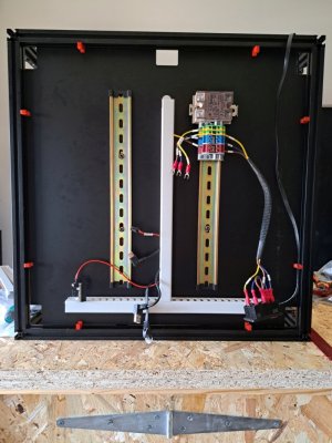
I have the 2.4 LDO kit and noticed that the build notes list installing the deck supports on page 29 of the manual (that's the page where you install the DIN rails). I searched through the manual on where those otherwise are installed but can't seem to find it? The supports are part of the Voron 2 Repo and do not seem to be an LDO specific part?

I tried to figure out how they might be installed, felt kinda silly as I didn't figure it out. I'm hoping I can install them after so I can proceed with the build (I'm on page 52, the print bed).

But yeah anyone have any thoughts or suggestions?
 
They just twist into the slot of the extrusion: It's basically the same motion as a hammer head nut, but in plastic.
 
As already said, they just twist in - I made the mistake of leaving them until later and installed LDO's cable trunking quite close to the edge on one side, which made it impossible to twist them in in the space. I had to remove the trunking to install them, which didn't come out as nicely as you'd hope and needed the tape replaced.
 
Ah hmm ok I thought so! I noticed they are asymmetrical but seemed like the short end was pushing up on the deck more than I expected. Now that I know I'm not doing it wrong I'll have another look. Thanks to you both! Cheers!
 
Thank you for reporting, you're the first one that noticed and spoke up :).
The supports were a late addition to the design and were not included in the CAD model when the manual was created. I'll put it on the list.
 
LDO has specific parts on their printed parts list. Went into the same and just installed some where I still could reach after everything was built up. Don't think they are crucial ;)
 
I ran into this exact same issue this week but couldn't find any example of installing them online. Had a "duh" moment after reading this thread.

I noticed that they have a hole embedded in them that looks like it would take a zip tie. Is this for help in wire management or does it serve some other purpose?
Correct, it is for wire management
 
Does anyone have a picture of where these clips are fitted to the bottom of the frame? Are they close to the steppers or in the middle. Also, how many are required?
 
Good question! I don't have a picture but for me I just put 2 on each side equidistant of each other and the sides. I'm not sure if that's the right way or best way but it's been working for me.
 
BTW, in case anybody else hits this, I'll just echo everything above and add one thing:

It seemed pretty simple to slide the 'barbed' end into the slot and turn, but I could not get them to turn! The printing of the part seemed fine. Got some pliers out to test it on more accessible extrusion, and it turned very easily. Weird. Tried it by hand then, and turned easily. Maybe the first turn had loosened it up? (no, see below) So I started putting them on, 2 per side, about a third of the way from each end. First two went easy, then I couldn't turn the third.

Finally took a second to look at the part. It's asymmetric. They turn easily one way, not the other. That must be what shiftingtech meant by "It's basically the same motion as a hammer head nut", but I didn't pick that up.

So, if you slide one in and it doesn't turn relatively easily, flip it over and try again. Also, I put them in with the shorter side towards the deck and the longer side just sticking past the bottom of the extrusion.
 
As of today, they still seem to be missing from the build manuals.
I was having some trouble with overextrusion and these would not go in, even with pliers.
Extrusion multiplier calibrated with a few test prints and now they are perfect!
 
Top