I'm writing a build log on my blog and reposting it here.
I’m not sure where it came from, but it was suddenly very important that I got myself a 3D printer.Maybe it was an important insight, but it maybe it was only a fix idea I got that somehow became this all-import thing.
Either way, I now have lots of parts for a VORON Trident 250 and I figured I’ll try to document the journey of building it (or failing to).
Now, a VORON is a really cool printer and there are lots of things that drew me towards it:
I got the 250mm version over the 300 and the 350 simply because it’s much easier to fit in my office and in my storage.I’m not planning to make any larger prints so the larger sizes felt unnecessary to me.
Now as I said a VORON isn’t a beginner printer, but I did take some countermeasures to hopefully make the build more manageable for me:
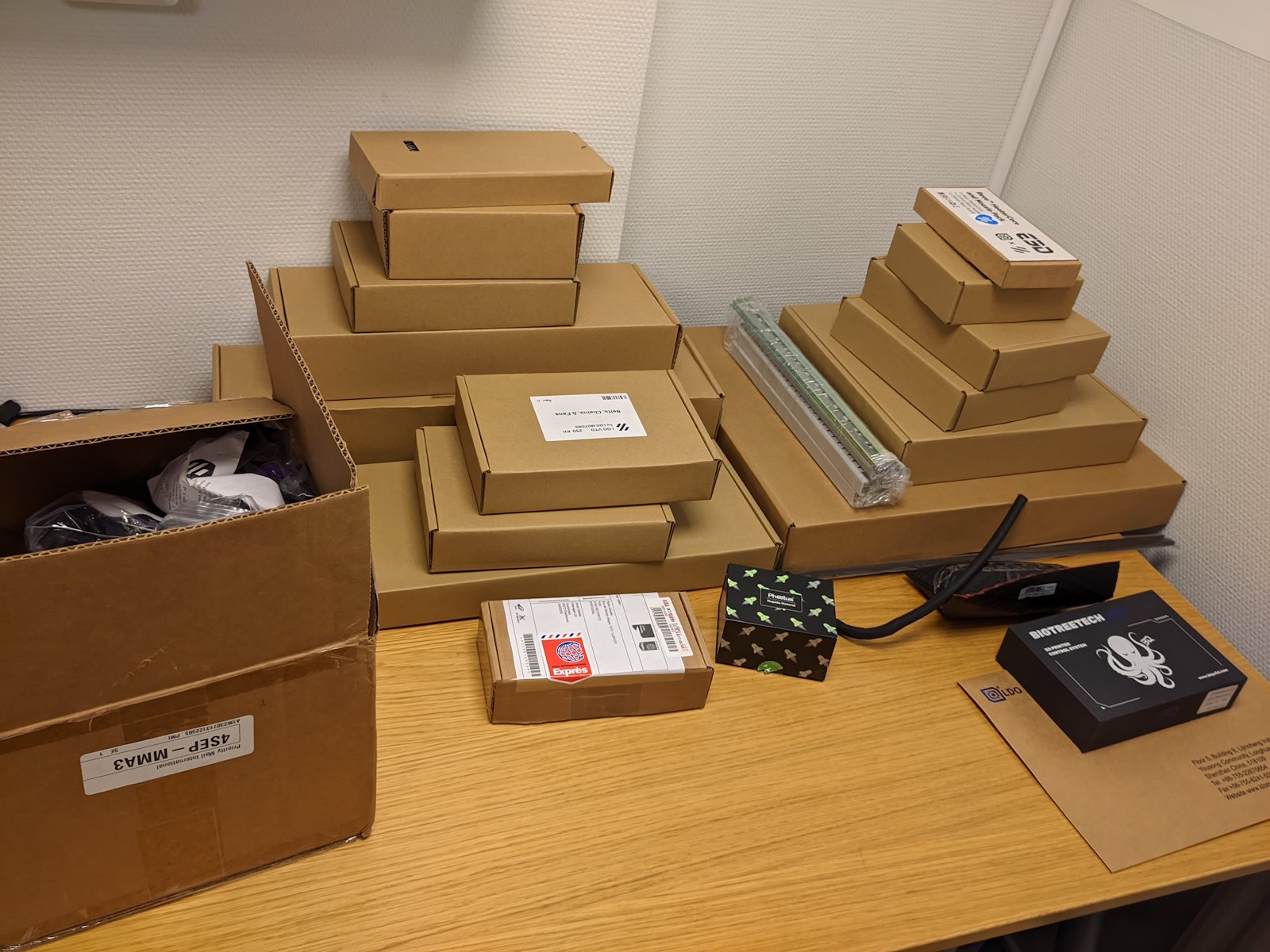 I’ve got a bunch of boxes
These are the items I’ve ordered:
But when I tried to cancel the order from caribou3d they told me they couldn’t make a refund as they had to declare insolvency. I did get a refund via PayPal, but I still strongly recommend you to avoid caribou3d.
But my big worry—that still isn’t resolved—is the preloading of the t-nuts.Apparently LDO’s combination of nuts and extrusions is very tight and you can’t (or it’s super difficult) to insert them after assembling the frame, so you have to insert them before.
There is a helpful video, but I’m still very worried that I’ve placed one of them wrong or missed some, and I have to disassemble the frame at a later stage.
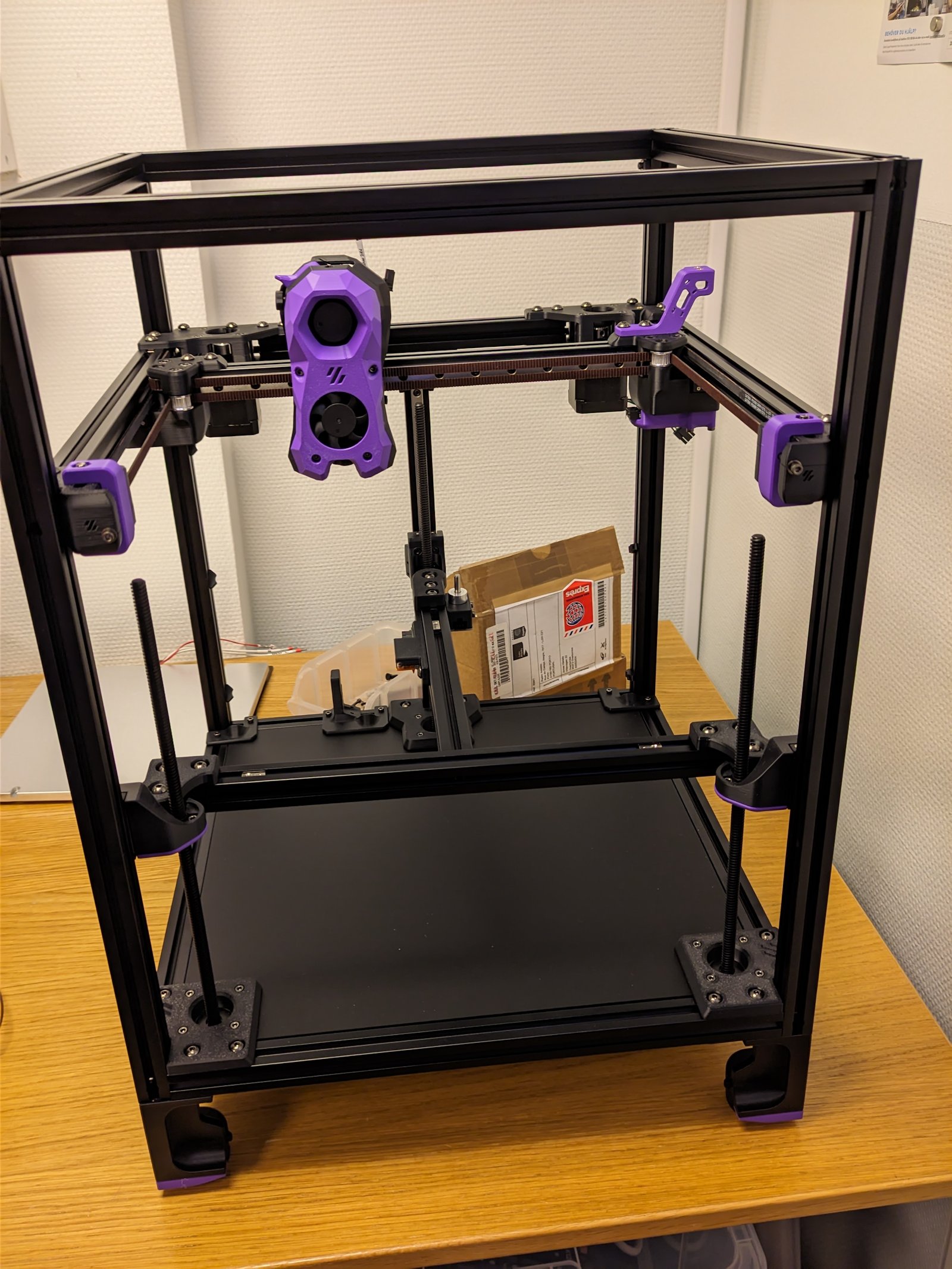
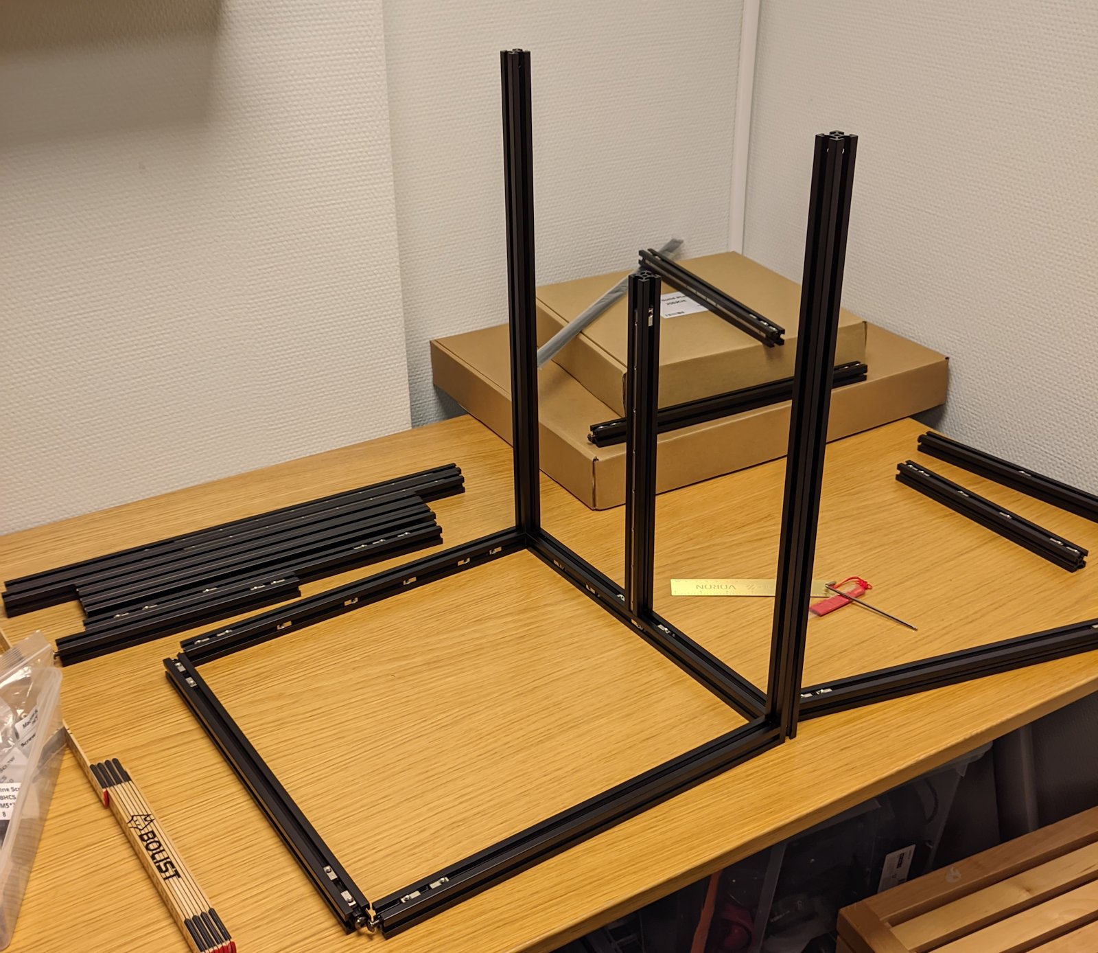 Assembling the frame. I really, really hope that I’ve placed the t-nuts correctly.
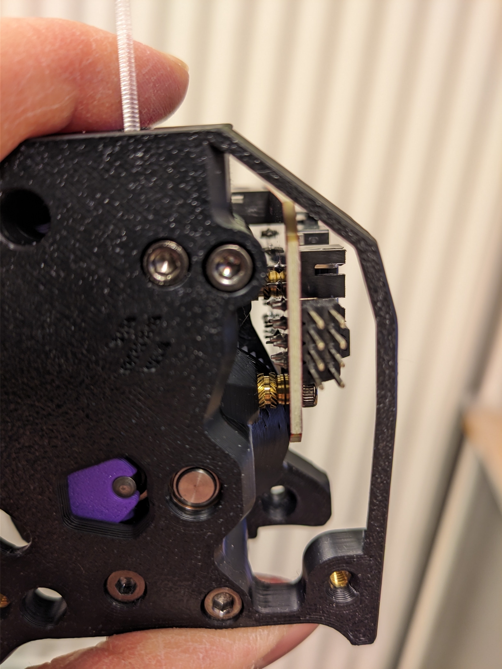
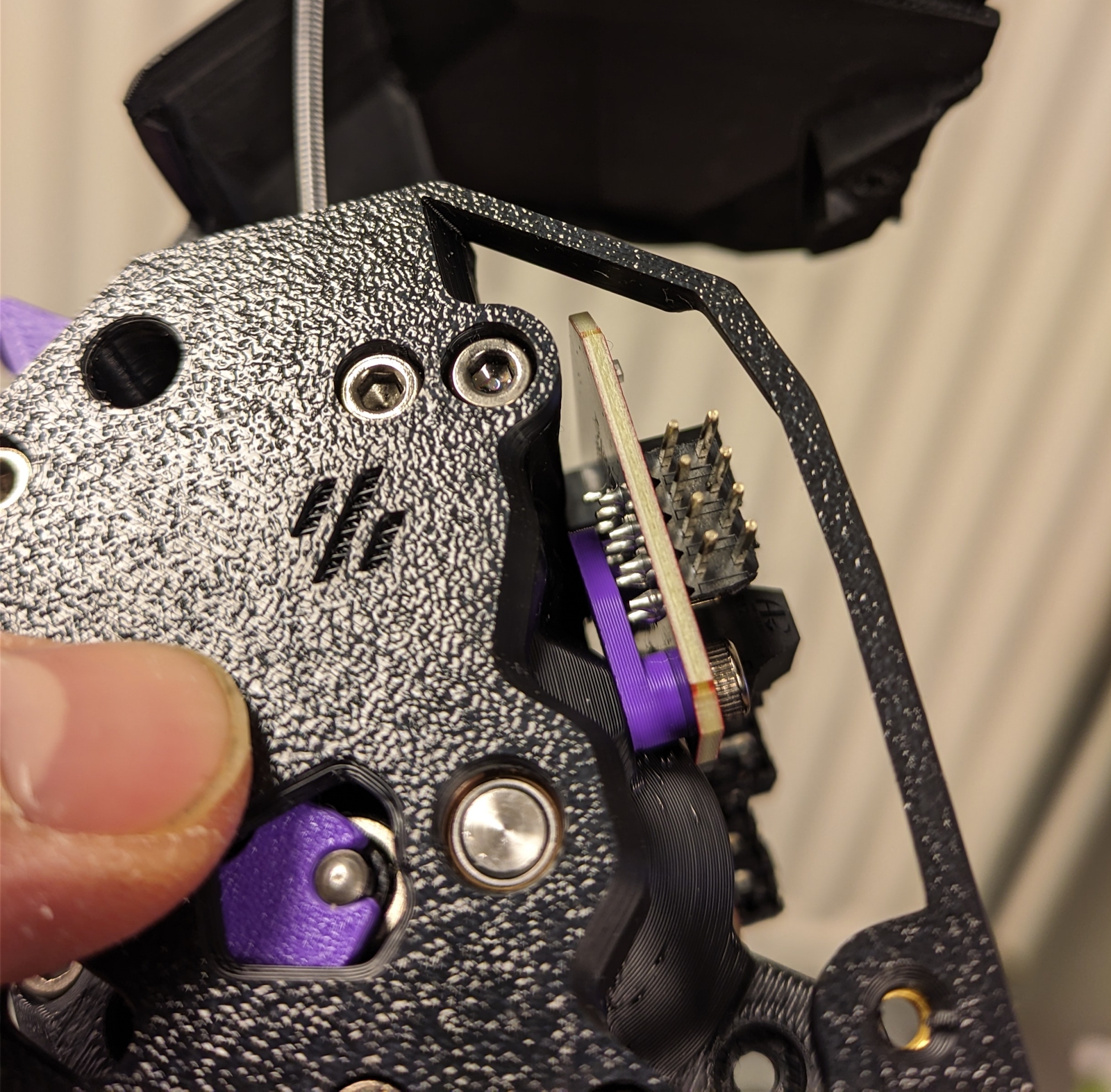
Turns out you don’t need it, and you can just use the soldering iron with a regular tip:
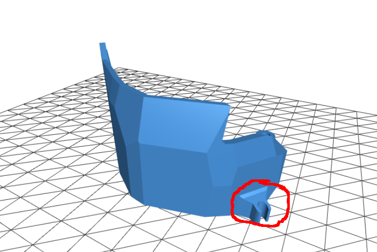
This works great.Except that I shouldn’t use this particular part in the build. Oops.
And I don’t even know what a “thread locker” is.
After some research time it seems I really do want a thread locker, but I live in a really small community and I don’t know where to buy this (except ordering online and waiting for a week).
Well maybe nail polish works just as well? So armed to the teeth with fire red lipstick I was ready to tackle the problem…
And I see that thread locker has been pre-applied to the set screws.Maybe it will pay off with the more expensive kit after all?
That’s great, but I also don’t have a syringe so I ended up removing the carriage and applying grease that way.To my surprise they were full of small balls that had a tendency to jump out at me.
The balls jumped out on me. I hope I found them all?
(No, I later found some missing balls…)
At first I applied a bunch of grease on the balls as well, but then carriage moved really slowly over the rails, so in the end I applied a little grease only in the middle.
They still don’t move as smoothly as they did when I opened the boxes, I hope it’ll be okay…
This is Loke’s hand.
I don’t want to publish pictures of my kids, so this is what you get.
So far the best part has been that both of my boys (5 and 3 years) have been helping me out, and they’ve been really enjoying being there and helping me tighten some screws.
I really want all my kids to build and be creative.Be it LEGO, sand castles, programming or 3D printers.So far this project has been promising, and at least the older one is super hyped about the prospect of building his own Nerf guns.I also want to build some toy robots and—when they get older—maybe a Quadcopter or two.
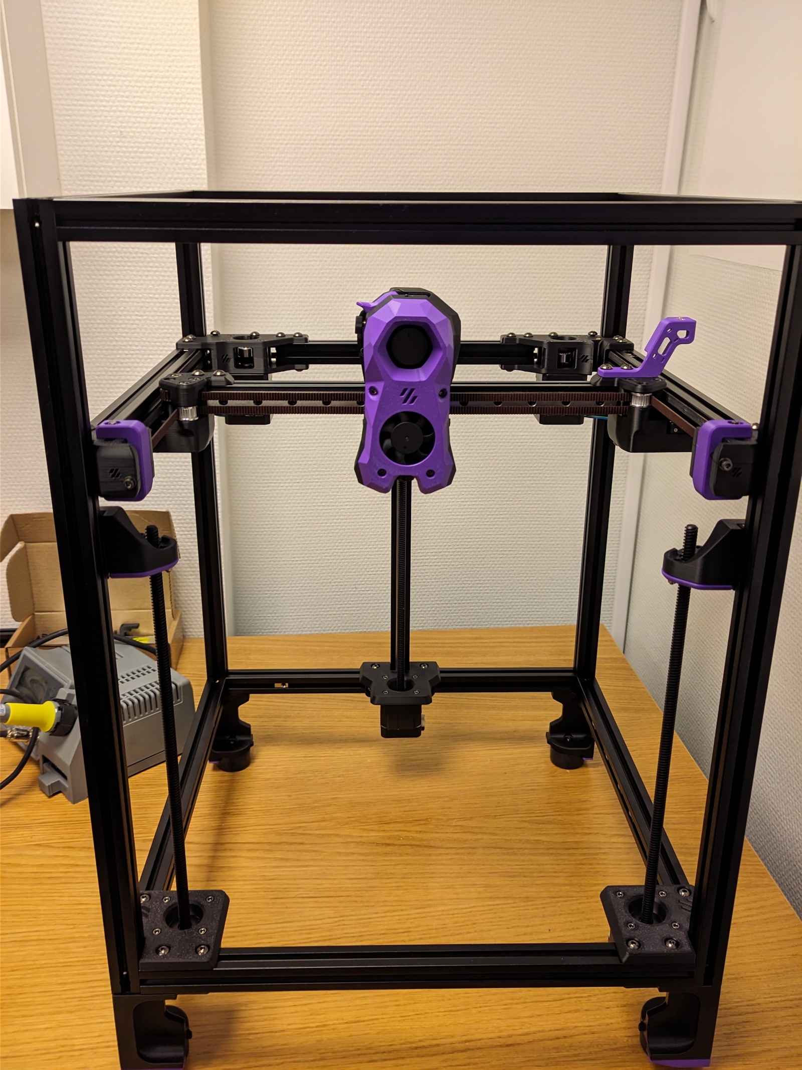
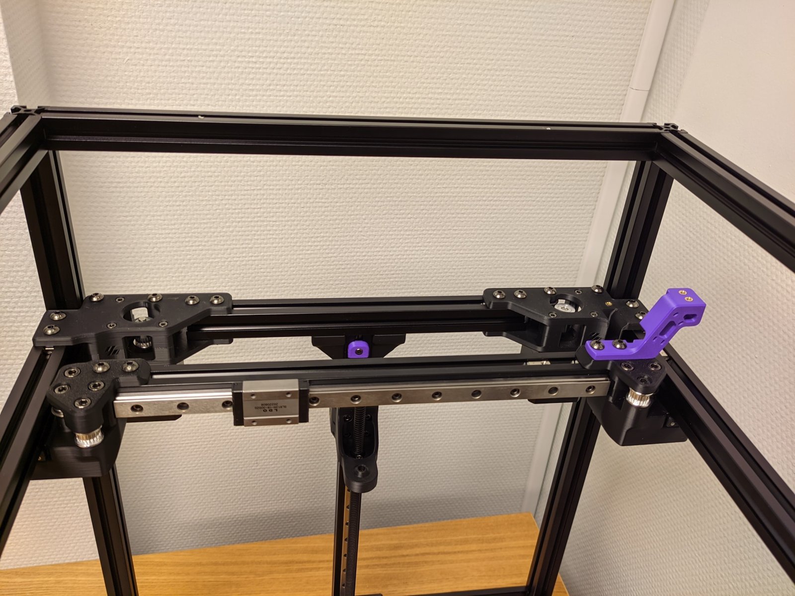
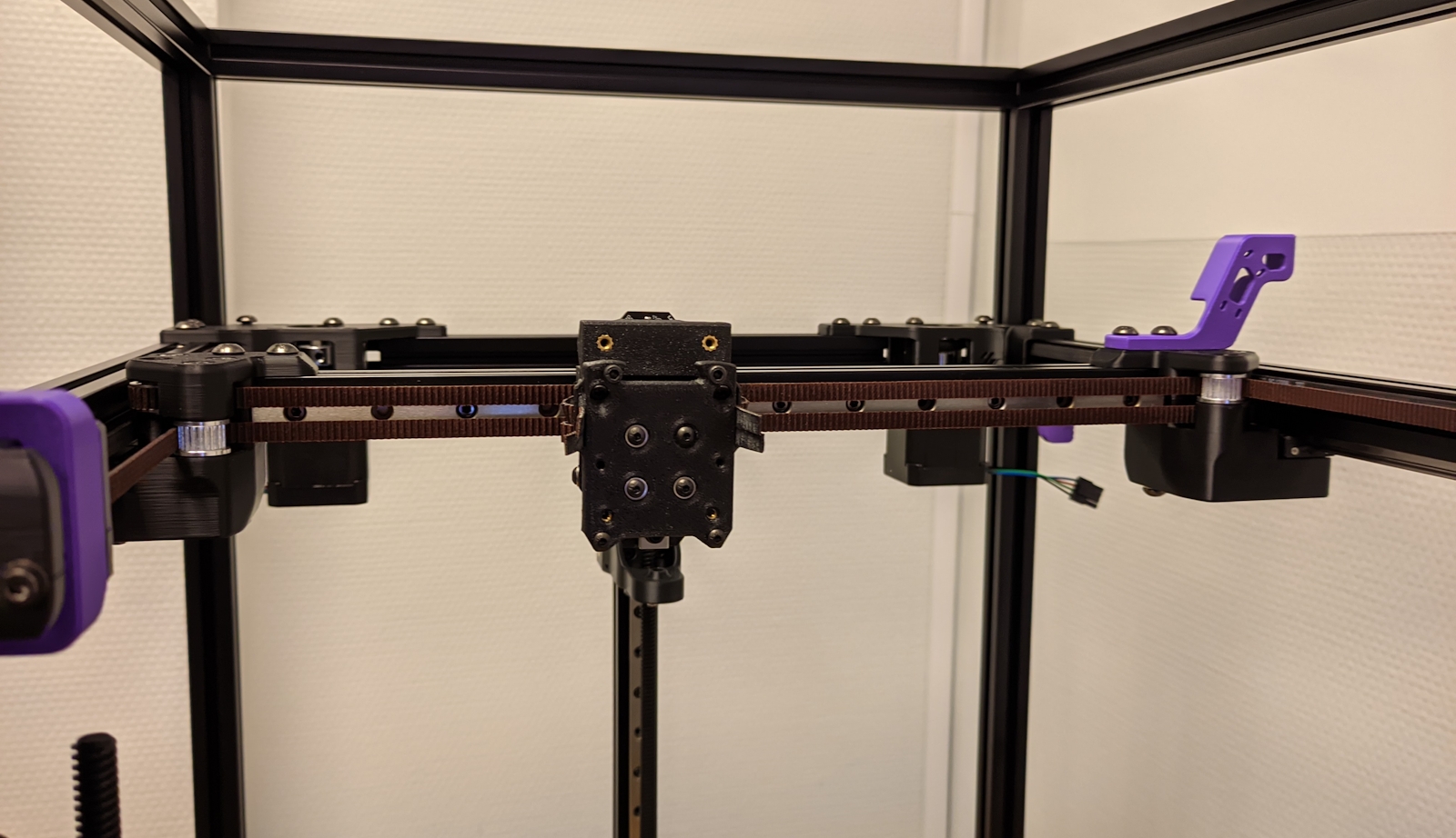
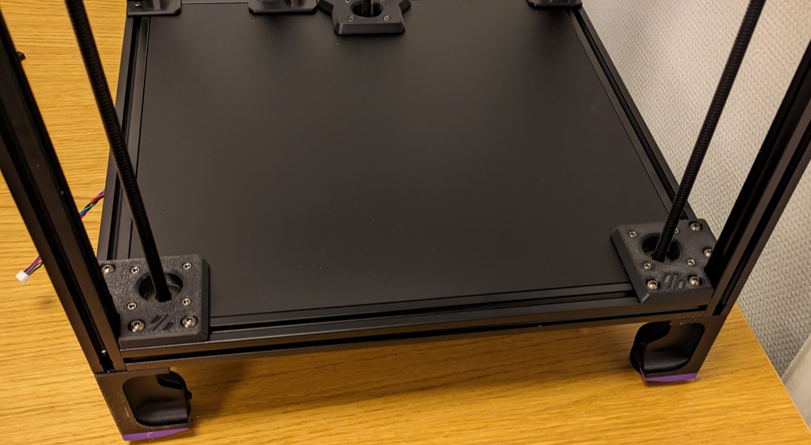
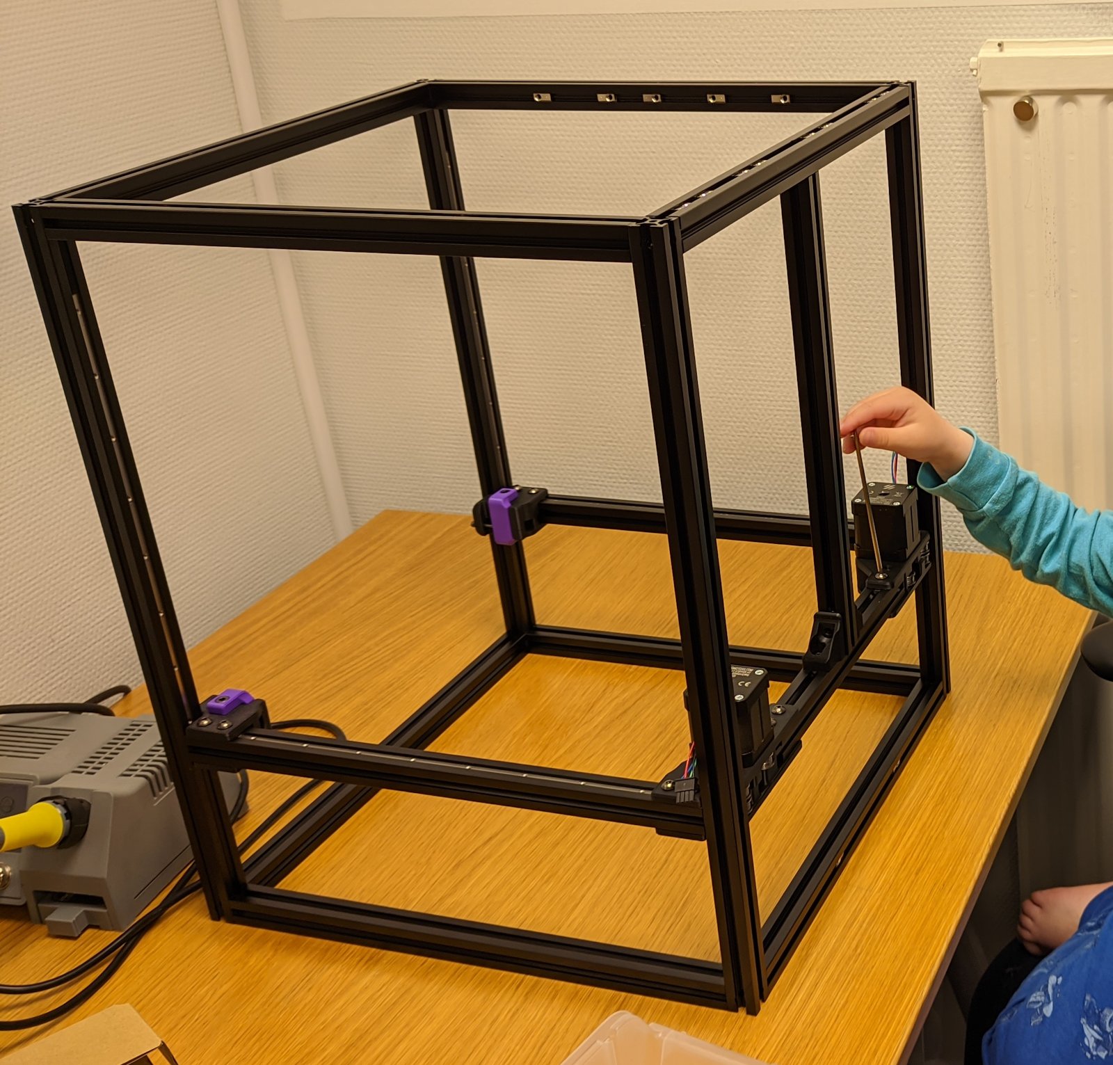
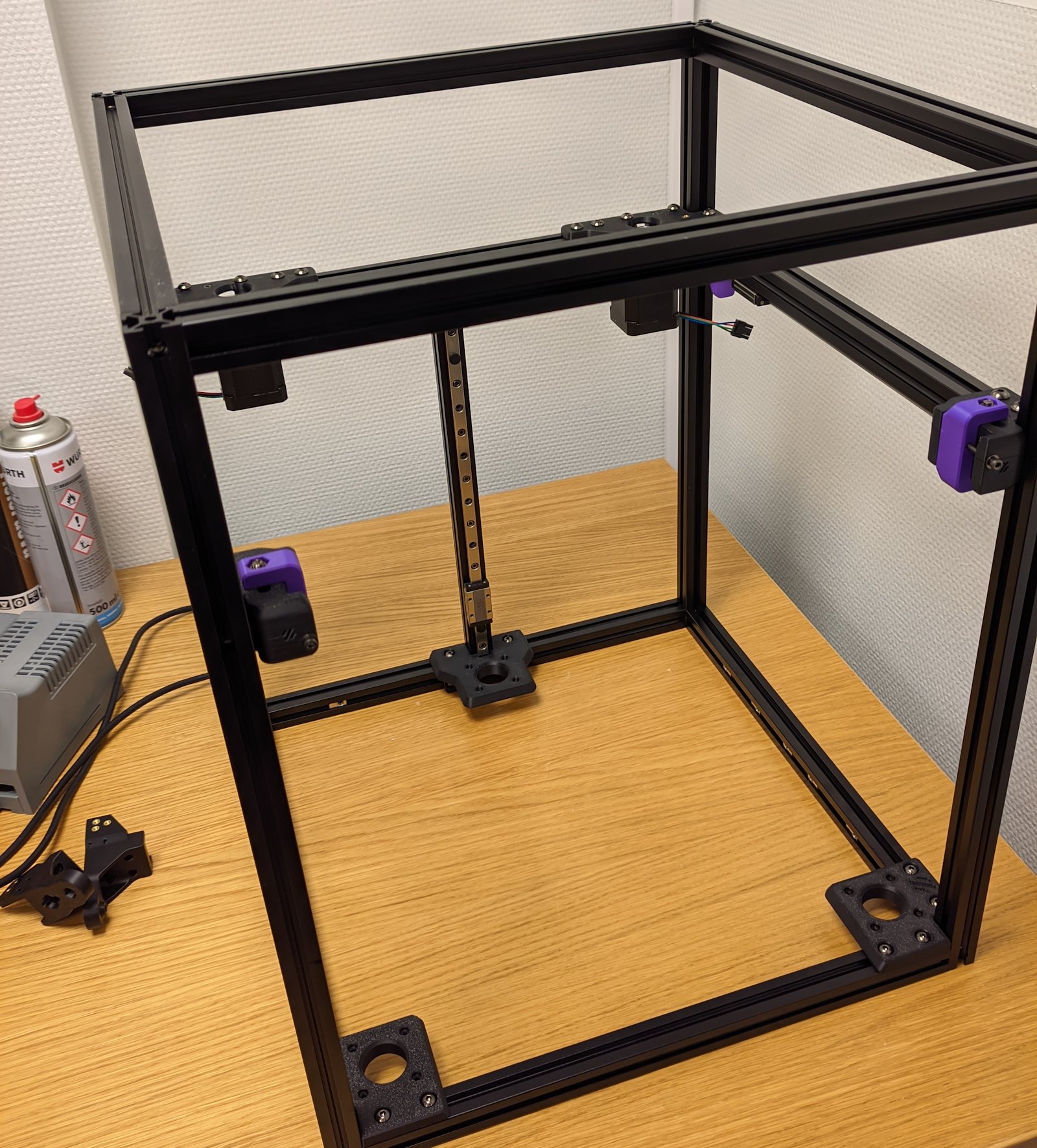 The frame is built and I’ve added three of the rails.
I’ve had the printer for almost one month and progress has felt slow.
I’m not sure where it came from, but it was suddenly very important that I got myself a 3D printer.Maybe it was an important insight, but it maybe it was only a fix idea I got that somehow became this all-import thing.
Either way, I now have lots of parts for a VORON Trident 250 and I figured I’ll try to document the journey of building it (or failing to).
Why a VORON?
The first step to building a 3D printer is deciding on what printer to build.This was roughly my selection process:- An Ender 3 seems like a cheap and popular printer, maybe that’s a good place to start?
- Hmm, the quality of an Ender 3 doesn’t seem that great and the internet says that you’ll spend a lot of time to tweak and modify it until you get something good.
- The Prusa MK4 has just released, and their printers have historically been really solid.
- Prusa seems open-source friendly (well, sort-of) but I’d probably want an enclosure as well…
- There is a Prusa enclosure, but holy crap it’s large and expensive. Maybe there’s something else that has a built-in enclosure?
- Damn, this VORON thing looks amazing and at around the same price range of the Prusa.
Now, a VORON is a really cool printer and there are lots of things that drew me towards it:
- It’s completely open source.
- The footprint is small and it comes with an enclosure.
- You can mod it to your hearts content.
- You build it from scratch, meaning you’ll get the knowledge of how to mod and repair it (I hope).
I got the 250mm version over the 300 and the 350 simply because it’s much easier to fit in my office and in my storage.I’m not planning to make any larger prints so the larger sizes felt unnecessary to me.
Now as I said a VORON isn’t a beginner printer, but I did take some countermeasures to hopefully make the build more manageable for me:
- I Bought the expensive LDO kit as it’s as close to a “just build it” kit you can find.
- I went with the Trident over a 2.4 because the Trident is supposedly a little easier to build.
- Even though the kit comes with the Klicky Mod, I want to use VORON Tap because I got this idea that Tap would be better.
At the moment I’m not planning to install Klicky at all, but we’ll see how that goes.
What I got
These are the items I’ve ordered:
- LDO VORON Trident 250
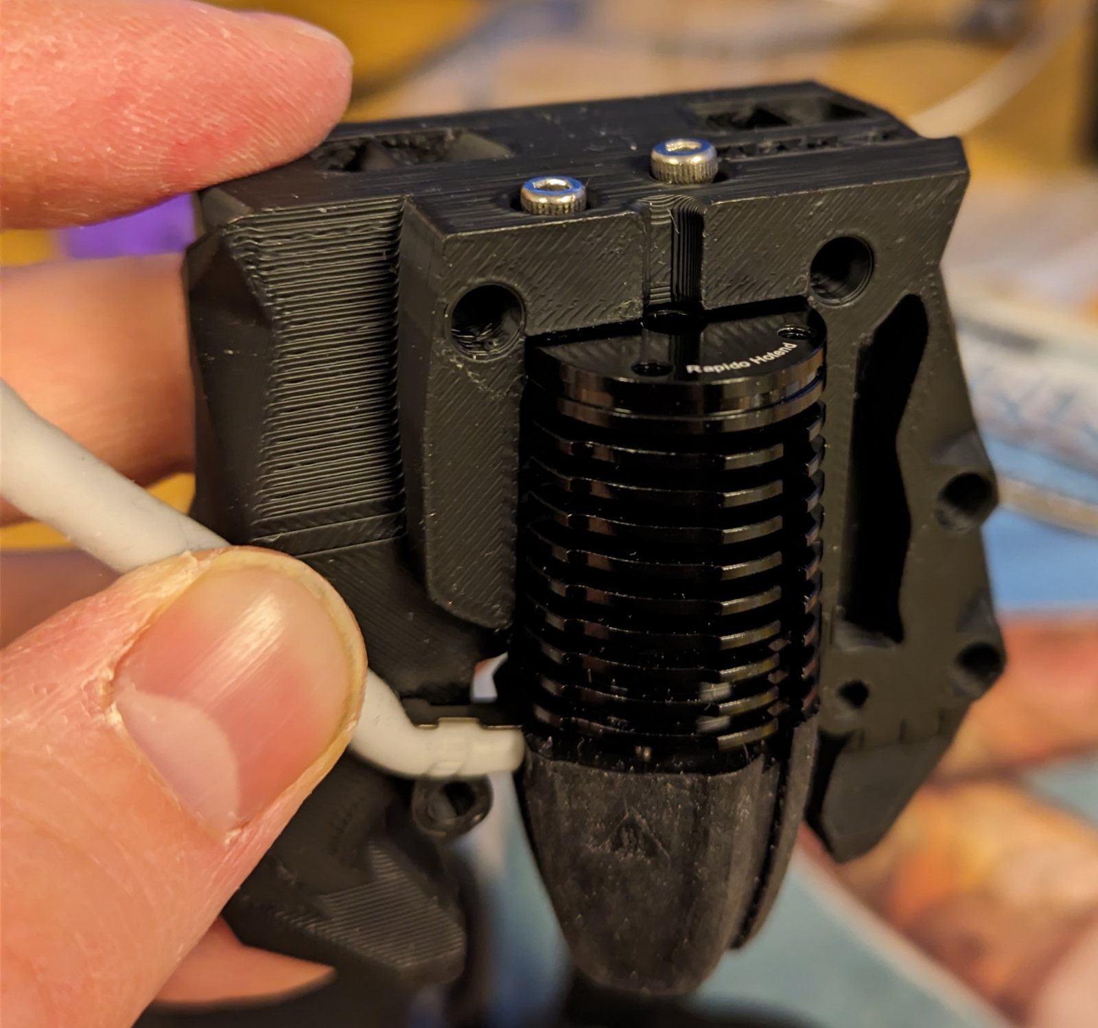
- Phaetus Rapido Plus Hotend UHF
- VORON Tap hardware kit
- Printed parts
But when I tried to cancel the order from caribou3d they told me they couldn’t make a refund as they had to declare insolvency. I did get a refund via PayPal, but I still strongly recommend you to avoid caribou3d.
Preloading the t-nuts
Assembling the frame wasn’t too bad.I took it easy to make sure I put the extrusions the right place, rotated as they should be.But my big worry—that still isn’t resolved—is the preloading of the t-nuts.Apparently LDO’s combination of nuts and extrusions is very tight and you can’t (or it’s super difficult) to insert them after assembling the frame, so you have to insert them before.
There is a helpful video, but I’m still very worried that I’ve placed one of them wrong or missed some, and I have to disassemble the frame at a later stage.
Heatset inserts
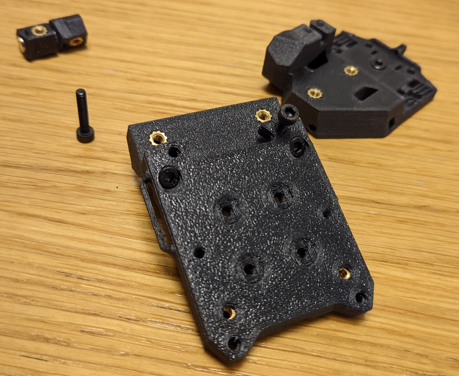
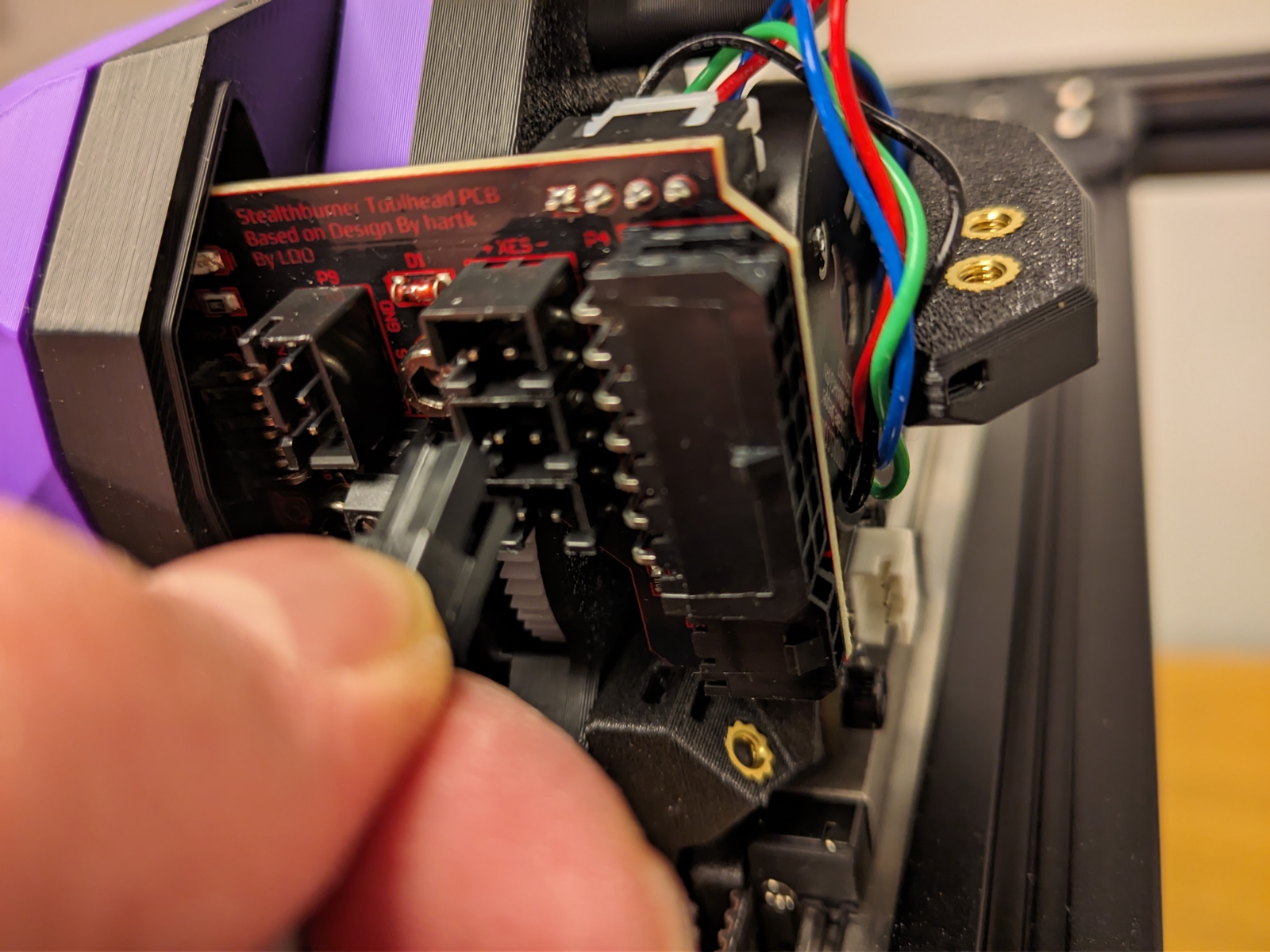
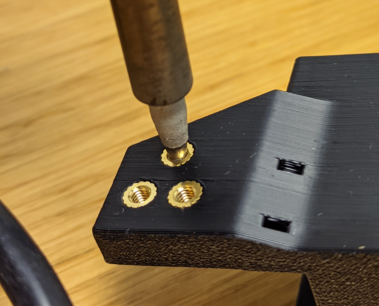
What to do with the heatset inserts? The LDO kit comes with a heatset insert tool… But it didn’t fit the soldering iron I had. What to do?Turns out you don’t need it, and you can just use the soldering iron with a regular tip:
This works great.Except that I shouldn’t use this particular part in the build. Oops.
Set screws
Another source of great worry for me was this line in assembly manual:Loose set screws account for the majority of issues that our users report.Save yourself hours of troubleshooting and apply thread locker to all set screws during the build.
And I don’t even know what a “thread locker” is.
After some research time it seems I really do want a thread locker, but I live in a really small community and I don’t know where to buy this (except ordering online and waiting for a week).
Well maybe nail polish works just as well? So armed to the teeth with fire red lipstick I was ready to tackle the problem…
And I see that thread locker has been pre-applied to the set screws.Maybe it will pay off with the more expensive kit after all?
Greasing the rails
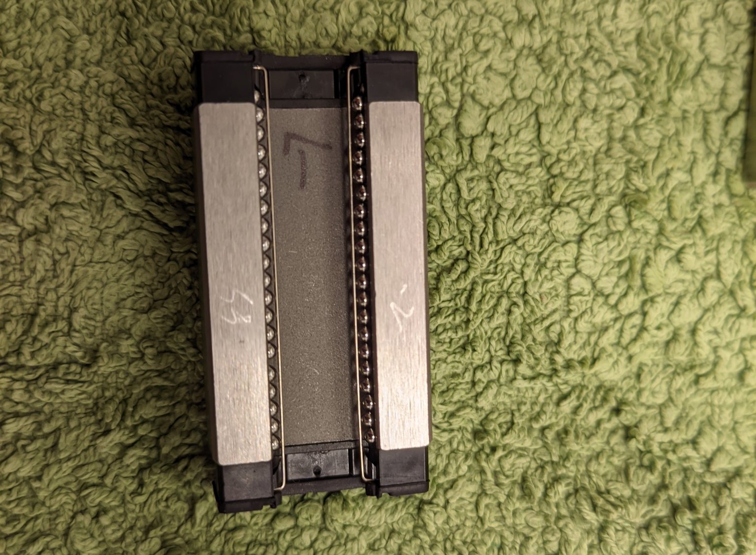
Greasing the rails is another thing that bothered me, because grease (and cleaning) wasn’t found in the kits I bought.My partners little brother came to the rescue and found a NLGI 1 grease (as recommended by the LDO guide) and some break cleaner to clean the rails.That’s great, but I also don’t have a syringe so I ended up removing the carriage and applying grease that way.To my surprise they were full of small balls that had a tendency to jump out at me.
The balls jumped out on me. I hope I found them all?
(No, I later found some missing balls…)
At first I applied a bunch of grease on the balls as well, but then carriage moved really slowly over the rails, so in the end I applied a little grease only in the middle.
They still don’t move as smoothly as they did when I opened the boxes, I hope it’ll be okay…
Best part of the build so far
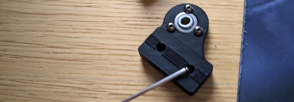
This is Loke’s hand.
I don’t want to publish pictures of my kids, so this is what you get.
So far the best part has been that both of my boys (5 and 3 years) have been helping me out, and they’ve been really enjoying being there and helping me tighten some screws.
I really want all my kids to build and be creative.Be it LEGO, sand castles, programming or 3D printers.So far this project has been promising, and at least the older one is super hyped about the prospect of building his own Nerf guns.I also want to build some toy robots and—when they get older—maybe a Quadcopter or two.
Where I’m at right now
I’ve had the printer for almost one month and progress has felt slow.
Last edited:
")