What's new
VORON Design

Register a free account today to become a member! Once signed in, you'll be able to participate on this site by adding your own topics and posts, as well as connect with other members!

LDO Trident 250, complete 3D printer beginner

My guess is that your kit is from when they used to have the hotend connect into HE0. Newer kits were changed to use BED_OUT due to how much power the Rapido draws those first few seconds (as well as to accommodate larger heaters for those using things like 70 watt or higher heaters).
 
I've got another question:

In the LDO docs it says to double check that 24V/GND and 5V/GND aren't shorted. But where exactly are 24V and 5V? I think 24V is the V+ outputs from the power supply, but where do I find 5V?

This is with almost all of the wiring, except fans, the problematic hotend cable and also without the bed connected.
Is there anything that sticks out before I can dare to turn it on?

I plan to disconnect the HE0 and Pi before doing it, and I've tested that the power supply turns on and its little lIght turns green before connecting the Octopus.

full_pre_power.jpg
 
The 5V would the power supplying the Pi. That's the little tophat PCB on the Pi. Your wiring looks good to me there, follows the LDO reference pic. But, double check the 24V wiring to your Octopus, it's not matching the LDO docs. I also notice you don't have the HE0 power to the breakout board--that's how your tool head is getting 24V.
 
Part 4


Dread it. Run from it. Wiring arrives all the same.

It’s time for the part of my VORON build that I’ve been dreading: the wiring.

It’s scary because I really have no clue what I’m doing, and mistakes can be very costly and time-consuming.

I’ve taken my time to double- and triple-check everything, and I took lots of pictures. I ran into some issues I’ll document here, but this post will mostly be filled with pictures to gawp at.

Cable chains

There wasn’t a ton of instructions on the cable chains, but I felt it went well.

I made some big mistakes here that caused major headache later on, but more on that later.

chain3.jpg
It was fiddly, but not the end of the world.
chain_pretty.jpg


top_motor_cables.jpg
If we make the wires pretty from the start, we can just continue like that?

Main power

Yes, I guess I should’ve connected main power before connecting the motor cables, but the octopus isn’t connected yet so it’s fine…

mains.jpg
I triple-checked that I don’t mix colors and I checked again that I connected it to the outlet properly.

Note that it says “TO 5V PSU” on the PSU cable. I think that’s a typo…

mains_light.jpg
The green light turns on! I’m glad it didn’t burn up yet…

Octopus power

According to the docs, the SSR should connect to HE0 instead of BED_OUT. Fine.

octo_power.jpg
The Octopus has the required power, but I didn’t check if it turns on at this point…

octo_power2.jpg
I mixed the 3 and 4 inputs on the SSR, but luckily I caught it when double or triple-checking.

Breakout cables

I’m following LDO’s wiring guide and the breakout cables are next.


Wrong hotend cable?

When I was about to connect the hotend cable I noticed a problem.

In the wiring guide it says that I should connect the hotend to BED_OUT:

Breakout PCBCable label (breakout)ControllerCable label (controller)
HE0 ****HE0HE0/PA2BED_OUT
****The BED_OUT port in the Octopus controller carries more current than the HE ports, this allows you to use super high power hotends such as the Phaetus Rapido.

But the cable that I got doesn’t fit:

wrong_hotend_cable.jpg
The hotend cable has “pin” type connectors.

My suspicion is that I got the wrong cable because the V2.4 wiring guide specifies that the cable goes into HE0 and SSR goes to BED_OUT, while the Trident has it reversed.

I complained about this to 3DJake (where I bought the kit from), who reached out to LDO where I got the response that they’re sorry, but I can connect the hotend to HE1 and change something in printer.cfg to make it work.

Not ideal as I do have the Phaetus Rapido, and according to LDO’s V2.4 errata it’s advisable to switch:

It has been reported that the Rapido hotend (by Phaetus) draws a large amount of current during initial heat-up. If you are using this hotend with our kit, please consider swapping the bed and hotend connections at the Octopus side.

I’m not thrilled about it, but I guess I need to find some spade terminals and change the wires later.

Full picture

breakout.jpg
A better overview of the wiring with breakout cables (and other things).

Raspberry

The Raspberry Pi uses 5V from the Octopus via some PCBs:

raspberry.jpg
The Raspberry Pi is connected.

raspberry.jpg
The Raspberry Pi is connected.

Other small details

The major things are done, but there are more things that needs to be fixed.

LEDs

I got a cute little PCB for connecting two LED strips in the kit.

led_pcb.jpg

It’s neat. I like it.
(I later moved the LED wire so it goes down in the front instead of behind the belts.)


leds_mounted.jpg
I wasn’t sure how to mount the LEDs, so I added a wire cover below the LED strips to give it a platform to attach on.

Controller fan

I should’ve gotten another PCB mount to mount the fan PCB, but I didn’t get one from the print-it-forward service. Maybe I should’ve mounted the fan PCB with the mount instead of the LED PCB, but I couldn’t be bothered.

fan_pcb.jpg
Some tape to prevent shorts.

fan_pcb2.jpg
It was hell to get it mounted. Why didn’t I do this before adding wires…?

Display mount

I didn’t manage to get the display mount to work properly. The screws didn’t align properly and the display cover constantly fell off.

mount2.jpg
There’s a space here that I couldn’t close no matter how hard I pushed.

mount_bad.jpg
The screw hole is slightly off.

I had to use tape to keep it all together:

mount_bad3.jpg
Tape for the cover so it doesn’t fall off.

mount_bad4.jpg
Tape for the sides.

It works I guess but I need to print new mounts when I get the printer up and running.I believe the problem is that I have the 2.1 version of the display, while the mount is for the 2.0 version.
 
Part 4b


The bed

I had delayed installing the bed, but with the wiring needing to be done it was time to install the bed.

I was a bit worried about applying the magnetic sheet, but I think I managed to do it without any bubbles.

bed_wired.jpg
The bed is installed and ready.

Maybe the Z-endstop is completely unnecessary as I’m going to run Tap?Probably, but as it’s already installed I won’t bother ripping it out now.

Missing Toolhead cables

When assembling the stealthburner I couldn’t connect the hotend to the toolhead PCB because the connectors didn’t match, and I also didn’t have a cable from the Tap PCB to the toolhead PCB.It was time to rectify that.

I didn’t do it when building the toolhead because I didn’t have the tools for it.So I ordered wire strippers, a crimping tool, JST connectors and some wire from Amazon.

No, I didn’t have a wire stripper and I’ve never created a cable before.

crimp.jpg
Crimping was fiddly but after a dozen attempts I think I got it down.

After I painstakingly created the Tap cable—with a 3-pin JST on each end—I noticed that the Tap PCB required a smaller connector than the ones I had. Oh no… Do I have to order another connector kit?

But luckily the Tap kit came with one such connector.(Please don’t break it.)

So I tried to change it… But after trying for some time I noticed that the wires I had were too thick, and didn’t fit this smaller connector.I nearly destroyed the connector while trying to insert the wires…

Things aren’t going my way, maybe I need to order (and wait for) new wire?

But wait!

Remember how I complained about the hotend cables having the wrong connector? Turns out the Rapido comes with extension cables with the connectors I wanted.The thermistor extension cable has thinner wires and the same JST connector I have…

Maybe I could shorten that cable and use the leftover wire for the Tap cable?

short_cable.jpg
A shortened extension cable for the hotend thermistor.

own_cable.jpg
Behold! My glorious cable!

I’ve spent an embarrassing amount of time and energy just to create this single cable. It makes me really appreciate that the LDO kit comes with pre-made wiring,I can’t imagine the frustration if I had to create all wiring from scratch (there’s a lot of it).

One problem I still have is the excessive wiring coming out from the toolhead, and I don’t really know what to do with it.

cable_bundle2.jpg
Too many cables. Should I try to hide it inside the cable chain?

Maybe I could try to shorten them all…But I’m not skilled or brave enough to try.

cable_bundle.jpg
It’s not pretty… It sort of ruins the nice looking toolhead don’t you think?

Gantry racking

When building the printer I’ve been jumping around a little, and somewhere in the middle of the wiring I decided I should try to solve the gantry racking.

I had noticed that the gantry catches a little when moving it around, and I got a tip from the VORON forum that I should rack the gantry to try to fix it.

And it did solve the issue! The movement isn’t as smooth as in NERO 3D’s video, but at least it doesn’t catch anywhere.
I did this with the motors and everything connected, which is NOT recommended as it may damage the components.At one point I saw the display flashing and thought “huh, that’s weird”, but clueless as I am the implications didn’t register at that time.

Yeah I know that NERO 3D said to watch out for it in the gantry racking video, but it had slipped my mind.Now I’m really worried that I’ve screwed myself over in a major way.

Lack of range for the toolhead

After installing the bed and racking the gantry, I noticed a big issue with the toolhead: it doesn’t reach the corners of the bed and the bed doesn’t reach up to the toolhead.

short_x.jpg
The toolhead is at max x, but it’s far from the edge.

short_y.jpg
The toolhead doesn’t reach the edge on the y-axis either.

short_z.jpg
I tried to raise the bed as high as possible, but it doesn’t come close to the toolhead, let alone raising it for tap to function.

Turns out I had made a mistake when installing the cable chains, as they’re all too short and they max out too soon, stopping the movement.

There were 4 extra links in the kit, but I didn’t know what to do with them so I forgot about them and took for granted that the three cable chains would work as-is. Maybe this is assumed knowledge, but when installing them—and before running the wires through—I should’ve checked the range of motion to be sure they were long enough.

Now I had to break open the chains and add the extra links afterwards. This was super annoying because I had to pull more wire to the chains, meaning I had to undo all the wiring work for all the motors and toolhead cables.

redo_chain.jpg
Opening up the xy cable chains.

I added two links to the z chain and one link each to the x and y chains.For x and y I also had to add some extra space by offsetting them so the chains aren’t flush to the edge of the extrusion holder or toolhead.

redo_chain2.jpg

I had to add some extra spacing on the x and y chains to get the required range of motion. I wish I hadn’t clipped away the tab, so I could zip tie the cables to it.


It’s all coming together

full_wiring.jpg

All the wiring is in place.
(You may notice an unconnected cable in the upper right, it’s for the Nevermore filter I haven’t built yet).


I may clean it up a bit after I’ve verified that things work.It may not be r/cableporn neat, but it could be worse.

nice_wires2.jpg
A better overview of the wiring with skirts and all.

Let there be light

With everything prepared I closed my hands, curled my toes, and clenched my ass and turned on the power…

And the lights are glowing! Huzzah!

octopus_lights.jpg

The lights are glowing, and there’s no smoke from the Octopus.
I disconnected the hotend and Raspberry as a safety measure before turning it on.


pi_lights.jpg
The Raspberry Pi also has some lights when turned on.

The status lights are promising, but I can’t tell for sure before flashing.
 
Part 5a


The build continues, now in a little more familiar territory.

Firmware flashing

To flash the firmware I had to order a microSD card reader.With that on hand the flashing wasn’t difficult. The VORON docs walks you through the installation very well.

Mainsail

I chose to install Mainsail instead of Fluidd simply because I liked the screenshot a little more. From what I understand they’re very similar and the choice doesn’t really matter.I flashed it using pi-imager.

It was great to see the display turning on and being able to ssh to the Pi—such a relief!

display_alive.jpg
The Raspberry Pi and the display are alive and kicking, although the display is rotated 180 degress.

After installing the Octopus firmware on it’s SD card and adding the device to ~/printer_data/config/printer.cfg I could start messing around with the Mainsail web interface.

Code:
[mcu]
# This is my serial, not yours
serial: /dev/serial/by-id/usb-Klipper_stm32f446xx_140045000F50535556323420-if00

mainsail.png
The Mainsail web interface.

KlipperScreen

It’s good to see my old friend the Linux login prompt on the display, but that’s not really what we want here.Instead we should install KlipperScreen to be able to control the printer via a user-friendly UI. I installed it using a manual install, but in hindsight I maybe should’ve KIAUH. Oh well.

To rotate the screen you edit /boot/config.txt according to the LDO docs:

Code:
# Make sure this line is commented
#dtoverlay=vc4-fkms-v3d

# Add these 2 lines to the end
display_lcd_rotate=2
dtoverlay=rpi-ft5406,touchscreen-inverted-x=1,touchscreen-inverted-y=1

klipperscreen.jpg
The display is rotated and uses KlipperScreen.

Home Assistant

trident_ha.png


Home Assistant integration with plenty of controls and sensors.


Of course, I had to hook up the printer to Home Assistant. This was easily done using the Moonraker Home Assistant plugin via HACS.

Maybe I’ll actually make a functional dashboard with it… Some day.

Initial config

It’s not enough to install the firmware, there are quite a few things in ~/printer_data/config/printer.cfg that needs to be changed. I used the LDO config as a starting point and went from there.To not bore you to death I’ll try to only document the noteworthy changes I made.

And—very importantly—I installed Neovim on the Raspberry Pi I using snapd. While I have the configuration files in a git repo, it’s far easier to ssh and edit the files directly.

Be careful

As advised in the VORON initial startup docs when testing these things (motors in particular) you should have a tested way of stopping the printer if something goes wrong. Like if you’re ramming the toolhead against the edge or something.

I… Didn’t do this and just saw the “Home” button and thought—I wonder if it moves when I press this?

Luckily the XY motors worked as expected (I hadn’t configured Z yet) but it could’ve been very bad.

Bed

The bed—through the SSR—is connected to HE0, corresponding to the PA2 pin (BED_OUT is PA1):

Code:
[heater_bed]
# SSR Pin - HE0
heater_pin: PA2

Hotend

The hotend is connected to the non-standard HE1 (since my cable didn’t come with a fork spade to connect it to BED_OUT, as advised in the LDO wiring docs):

Code:
[extruder]
# Heater - HE1
heater_pin: PA3
sensor_type: PT1000

It also took a long time for me to figure out the correct sensor_type value.None of the values in the common thermistors documentation worked for the Phateus Rapido, but I found an off-hand comment somewhere that PT1000 was the correct type.

Tap

Configuring Tap was straightforward, I simply followed the steps in the Updating your Klipper config for Tap instructions.

The one thing that confused me was this this line about PROBE_CALIBRATE:

You’ll need to manually calibrate the probe’s Z offset by using PROBE_CALIBRATE.

Turns out it’s the process described in configuring the Z Offset Adjustment in the VORON documentation, only substituting Z_ENDSTOP_CALIBRATE with PROBE_CALIBRATE. I ended up with this line in the config:

Code:
#*# [probe]
#*# z_offset = -1.195

To see if Tap is working I warmed up the enclosure a little bit I ran PROBE_ACCURACY:

Code:
probe accuracy results:
    maximum -1.219375, minimum -1.221250, range 0.001875,
    average -1.220500, median -1.220625, standard deviation 0.000612

According to the docs the standard deviation falls within the expected range of a well-built machine:

For well-built machines you can expect to see between 0.0000 and 0.0008 standard deviation.

I doubt that I built everything that well, but I’ll take it!

I’m a little confused what the negative numbers mean; is my z_offset too low, causing the probe values to be negative?Or are they uncorrelated and this is completely fine?

Extruder

It’s weird. In some cases you can move mountains and solve the most difficult problems in a flash, but at other times you’ll stumble on the smallest pebble.

And I stumbled hard on inserting filament into the extruder.

I know I checked it when assembling the Clockwork 2, but by god I couldn’t get it to grab on the filament. After a long time of fiddling, and considering if I should just disassemble it all, I somehow got it to work.

I think it was a combination of the extruder direction being inverted and some filament getting stuck, but I just don’t know. I’ll file it under user error and forget about it.

Code:
[extruder]
dir_pin: PF0 # Inverted by removing the `!`

I don’t understand how you’re supposed to properly measure the amount of filament when calibratingthe extruder, the VORON docs isn’t particularly clear about it. What I did was to pull it taught and try to measure from there, but I fear it wasn’t that precise.

Maybe it would be easier without the top panel?

extrude_calibration2.jpg
The small red mark was 100mm away from the edge of the black holder part before I tried to extrude 100mm of filament. I think this is good enough?

Code:
[extruder]
rotation_distance: 20.41105599   # After recalibration

extrude_calibration.jpg
I hope my first print will look better than this mess?

 
Part 5b


Panel mounting

You may have noticed that the above pictures had panels on them. That’s right, to be able to heat soak the printer I had to have the panels, so I quickly installed them.

front_mounting.jpg
It was easier to align the doors with the printer lying down.

front_magnet_mount.jpg
How are you supposed to get the right polarity and stick the part on the correct spot on the door? Just place the magnet and then push in the part.

I’ve been impressed with the build so far, but I’m not impressed with the doors. The doors doesn’t have foam tape between them and the frame unlike the rest of the panels.

I wonder why that is? I worry that they will scramble against the frame and it won’t make a good seal, which I think could’ve been avoided. I’ll probably look for mods for the doors; maybe I’ll replace the doors with a magnetically mounted panel or something.

Slicer

I do feel my 3D printing inexperience when I have to setup yet another thing: a slicer. There are quite a few options, but I didn’t care to try out them all—I simply wanted to get up and running smoothly.

I picked SuperSlicer because it works on Linux, has a custom Voron Design profile to import, and seems fairly popular.

superslicer.png
Viewing the layers is weirdly satisfying.

I was initially super confused on how to see the layer preview. Turns out there was some error with only using the preconfigured Voron v1 250 0.4mm config I selected in the configuration wizard.Importing the Voron Design profile and selecting it seems to have resolved the issue.

What’s left?

The next thing is finally to print something. Unfortunately I don’t have any filament other than the small sample that came with the LDO kit, so it’s back to waiting for a shipment to be delivered.

And after that there are still things left to do:
  1. I’m missing some printed parts that I need to print out myself.
    For example I need a rear exhaust cover (although I plan to add a HEPA filter there) and spacers to mount the handles.
  2. Tuning, tuning and more tuning.
    Prints needs to look good.
  3. Mod it.
    It feels wrong to build an incredibly moddable printer and leave it without any mods.I’m trying not to keep the “to-mod list” short but I can already sense that I’ll fail miserably.
full_with_panels.jpg
It works, but it’s not done yet.
 
Its looking good!

I found it much easier to calibrate the extruder without the Reverse Bowden tube installed. The Ellis tuning guide has some great pictures and suggests using tape rather than a sharpie marker. I found it much more precise. I have a 150 mm scale from Lee Valley that works absolutely spectacular for this. It has a ridge that makes it easy to get the filament straight and set the tape at exactly 120mm to start.
 
Looks great! You are basically off and running now. I agree the doors aren't spectacular, but they work fine as they are. My chamber gets plenty hot even with them basically stock.

Don't worry about the actual offset number. What you have is well within normal. As long as it's zeroing correctly you are fine.

For calibrating the extruder, I always measured from the top of the Stealthburner body. But again, as long as you've gotten it close to extruding 100mm when you tell it to all is well.

Next step is to go through the Ellis guide for your pressure advance and extrusion modifier. There's a ton of good information in there, so spend a while reading.
 
Part 6a


It’s up and running, and now it’s finally printing time!Less exciting—but necessary—tuning the printer to make the prints better.

Filament shipment

Even though I’ve been building the printer for more than a month, I wasn’t ready for it being time for printing so soon.I don’t know what filament is good and what I need, so I decided to get a few different brands and colors to try out:
filament.jpg
I think I went overboard with the filament order. In hindsight I should’ve waited longer to see what materials I wanted to print, now I kind of regret buying so much PLA.

Secondary printer tuning

At this point the next step in the VORON docs is making a print.But I had various issues, so I went through the Secondary printer tuning before getting my first successful print.

Gantry racking & squaring

I’ve already done the gantry racking, yay!

Belt tension

I always wondered how tight the belts were supposed to be.Tuning it by measuring the frequency using an app was pretty nifty, and it was quite painless.

belt_frequencies.png
It’s around 110Hz, I think?

I tried to tune it to 110Hz, but I’ve seen people aiming for 120Hz.

Bed mesh

To setup a bed mesh you just add something like this to Klipper:

Code:
[bed_mesh]
speed: 300
mesh_min: 40, 40
mesh_max: 210, 210
fade_start: 0.6
fade_end: 10.0
probe_count: 5,5
algorithm: bicubic

And then BED_MESH_CALIBRATE will do it’s job:

bed_mesh.png
The bed mesh is situated around 0, nothing unexpected here.

I also setup Klipper Adaptive Meshing & Purging (KAMP) using their setup instructions to dynamically adjust the bed to fit the print size.

Input shaping

The guide references input shaping, which is included in the LDO kit.NERO 3D recommended to wait with input shaping until you’ve printed with it a bit, so I did the input shaping after ~5 hours of printing time.

input_shaping.jpg
Input shaping connected.

I didn’t do anything special and just accepted whatever it spat out.

First print

The VORON docs makes the first print seem so simple—just upload the print and eat a bowl of cereal.And I was looking forward to just hitting print and watching it go brr…But of course things wouldn’t go so smoothly.

Problems I’ve had include but isn’t limited to:
  1. Print stopped with Hotend not enough
    This happens because the Tap G-code reduces the hotend temperature to 150° when probing to not damage the bed, but then the temperature is too low for printing.
    To fix it I had to manually set bed and hotend temperatures after Tap and modifying SuperSlicer to provide these values to the PRINT_START macro as detailed in a better PRINT_START macro.
  2. Filament didn’t load.
    And KlipperScreen complains about FILAMENT_LOAD not existing. Sigh.
  3. First layer not sticking to the bed.
    A combination of using the wrong temperature and z_offset was to blame.
  4. After a few failed attempts, the filament clogs.
    clogged.jpg
    The filament clogged somehow, and I had to disassemble the toolhead to fix it.
  5. Bunch of “Unknown command” errors in the mainsail log.
    I assume it’s because Klipper wasn’t selected in the “G-code flavor” in SuperSlicer.
  6. The print coming loose from the bed after a while.
    fail_print.jpg
    Oh FFS.
    I struggled with this a fair bit. I reconfigured z_offset which seemed to work, but maybe it’s extruding too much filament causing the toolhead to hit the print?
After all that trouble I was running into I was expecting for getting an absolutely shit print… But it’s actually not that terrible?


It’s far from perfect, but the lighting is fairly harsh and it looks better in real-life. My friends have shown many 3D prints that look a lot worse.

Functional prints

High on adrenaline I set out to do my first functional print: an exhaust cover for the back of the printer.I’m going to replace it with a proper filter in the future, but I wanted something to cover the big hole in the back when printing ABS, so I wanted to make a temporary in PLA.

But it things can’t go that smoothly:

fail_print_exhaust.jpg
I messed with the z-offset during print, and the result was this mess.

The printer made some extremely unpleasant sounds, and I was scared that the nozzle was grinding against the bed.I tried to tweak the z-offset during print, but I the sound didn’t stop and I ended up destroying the print.

The nozzle didn’t hit the bed and it was the stepper motors being super loud… But more on that in a future post.

When I re-ran the print and stopped messing with it, the printer spat out a functional print:

print_exhaust.jpg
Surprisingly good quality.

Other things weren’t that good:

not_great_nevermore_mount.jpg

A part needed to mount the Nevermore filter to the extrusion .It’s hard to see in this image, but the top edge is drifting upwards quite a bit.

Simpler models seem to print well, but it struggles with more complex geometry.While I can probably use this Nevermore mount with some sanding, this level of quality isn’t high enough to for example print parts for a VORON.

More tuning is needed.
 
Part 6b


More print tuning

Ellis’ print tuning guide seems like the go-to guide for tuning your prints.It contains a lot of info, so I won’t write about it too much lest we’ll be here all day.These are the big things I did:
  • Extruder calibration
    This contains the images on how to measure the extrusion distance I was missing from the VORON docs .I redid the calibration but with the top panel removed to get a more accurate measure. Turns out my previous calibration was 10% off. Yikes.
  • First layer squish
    I wasn’t really sure how to do this, but I think the point is to print one square using one z-offset and then change it a little for the next square to see which produces the best print. In SuperSlicer I had to enable the “Complete individual objects” setting for it to print one square at a time.
    My previous z-offset using the paper was pretty damn good, but I ended up accepting a -0.01 extra offset (increasing it to -1.050).
  • Pressure advance
    I used the pattern method, although there were so many settings I was unsure about so I don’t know how well it worked out.
    Still, I got a value of 0.04 and for some reason I didn’t have any pressure advance setting previously.
  • Extrusion multiplier
    It was super difficult for me to tune this as I wasn’t sure what to look for.I ended up choosing 0.98, but it could’ve just as well be 1.0. Apparently I should do this for every new filament? How bothersome.
There are more things in the guide, but they feel like issues you should keep in mind when printing and not something you tune for from the start. With the massive amount of tuning options both in Klipper and SuperSlicer I’m sure this will be a topic I’ll have to revisit many times.

Some more prints

I printed out another calibration cube and I hoped to have some good comparison pictures here,but truthfully the difference was really small.There were some slight improvements, but not something that shows up well in pictures.

So here are some other parts I’ve printed:

printing_abs.jpg
Printer goes brr.
printed_parts.jpg
Some of the parts for a HEPA filter housing. If you zoom in you can see some stringing and very visible lines.

printed_parts2.jpg
The print lines are quite visible.

Despite some artifacts I’m happy with these results,especially since these were new spools of filament that I didn’t do any tuning or drying for (I don’t have a filament dryer yet).The prints were absolutely good enough for me to start printing a bunch of mods for the printer.
 
Looks like PA could use a bit more tuning, but overall the parts look good. Your bed mesh also looks like the right rear Y extrusion is a touch high.
 
Part 7


I can print, but the printer is missing a very important thing that I alluded to in the previous post: filtering dangerous particles and fumes.

This is mostly covered by the kit, but I was missing some parts from the print it forward and the kit didn’t include a HEPA filter. Because the printer is in the office and health is super important fixing this was needed so I could start printing some ABS and continue modding the printer.

Exhaust cover

exhaust_cover_hole.jpg
I’m missing the exhaust cover where the filter goes in a stock VORON.

The standard VORON comes with a filter in the back, but the LDO kit doesn’t include the fan for the filter and instead uses an exhaust cover to close the hole.

I didn’t receive this part, so the first thing I did was to print that part.This was just a very temporary measure so I printed it in PLA.

Nevermore filter

nevermore_installed.jpg
The Nevermore filter is installed next to the back panel.

The LDO kit includes the Nevermore filter, which removes VOCs.I was confused on how to install it as at the time the LDO docs only mentioned how to install it on a 2.4, not on a Trident. When I brought it up they fixed it so no big deal.

But they wanted me to mount it using a plenum mount, which my parts didn’t have.I think I received an older version of the Nevermore from the print it forward service so I couldn’t use it.

I instead printed out the updated plenum and frame connector myself.Because the point of the Nevermore is to be able to print ABS safely I did this in PLA as well. I know it’s not ideal, but it will have to do.Lazy as I am I’ll run with this and if it breaks I’ll replace it then.

I also added some strips of foam tape to the back of the filter to prevent it from scrambling against the back panel.

nevermore_fans.jpg
Cutting away parts from the fans was horrible. They broke very easily.
nevermore_solder.jpg

I finally got to exercise my (very poor) soldering skills! It was cute how LDO included a small board so that you don’t have to crimp any cables.

HEPA exhaust filter

hepa_filter.jpg
A new HEPA filter. I wasn’t able to color match with the print-it-forward parts…

While I have the Nevermore filter, it doesn’t filter Ultra-Fine Particulates. For that you need a HEPA filter.

There were a few solutions with combined carbon and HEPA filter, but since I already have the Nevermore I wanted a standalone HEPA filter. I found the Voron HEPA Exhaust Filter that replaces the stock filter that seemed like a good option.

With the Nevermore in place I could print the parts using ABS, and they turned out pretty well.

For silence I used a Noctua FN-A6x25 fan. In hindsight I maybe should’ve used the PWM variant, if only to make the wiring simpler. Now I have this ugly looking wiring in the top corner (it uses the Noctua low-noise adapter).


I also had to create another cable, which wasn’t too difficult:
  1. Converted the 3-pin cable to a 2-pin JST connector and extended it.
    I simply ignored the yellow RPM speed signal cable.
  2. Connect to a free fan output on the Octopus.
  3. Used the 12V selection jumper for the fan output.

Klipper setup

With the fans installed you also need to configure Klipper to utilize them.

I setup them both as generic fans, so I can control them from the start and end macros:
Code:
[fan_generic nevermore_fan]
##  Nevermore fan - FAN3
pin: PD13
max_power: 1.0
kick_start_time: 5.0

[fan_generic filter_fan]
##  HEPA filter fan - FAN4
pin: PD14
max_power: 1.0
kick_start_time: 5.0

Then in PRINT_START I turn on the fans:

Code:
SET_FAN_SPEED FAN=nevermore_fan SPEED=1
SET_FAN_SPEED FAN=filter_fan SPEED=1

After the print has finished I don’t want to just turn off the fans immediately, but have them run a bit after the print has finished to clear out any toxic fumes.I accomplished this with a delayed_gcode:

Code:
[delayed_gcode _VENT_OFF]
gcode:
SET_DISPLAY_TEXT MSG="Venting done"
SET_FAN_SPEED FAN=nevermore_fan SPEED=0
SET_FAN_SPEED FAN=filter_fan SPEED=0

That I call in PRINT_END with a timeout:

Code:
# Turn off fans after 30 min
UPDATE_DELAYED_GCODE ID=_VENT_OFF DURATION=1800

To prevent the fans from turning off mid-print if I get impatient and start a new print before _VENT_OFF has been called I also clear the delayed gcode in PRINT_START:

Code:
# Prevent Nevermore and filter fan from being turned off mid print
UPDATE_DELAYED_GCODE ID=_VENT_OFF DURATION=0

And now the filter fans turn on and off automatically.

Some people run the Nevermore on 50–80% during print and then go 100% at the end, but I don’t know why you can’t run it at 100% all the time so that’s what I do.
 
I also rewrote the PRINT_START and PRINT_END macros to make a little more sense to me. Here they are in their entirety:

Code:
[gcode_macro PRINT_START]
gcode:
  # Fetch data from slicer
  {% set target_bed = params.BED|int %}
  {% set target_extruder = params.EXTRUDER|int %}
  {% set target_chamber = params.CHAMBER|default(0)|int %}

  # Set temps for bed and extruder without waiting to save some time
  SET_DISPLAY_TEXT MSG="Preheating"
  SET_HEATER_TEMPERATURE HEATER=heater_bed TARGET={target_bed}
  SET_HEATER_TEMPERATURE HEATER=extruder TARGET=150

  SET_DISPLAY_TEXT MSG="Homing"
  G28                                                     # Full home (XYZ)
  G90                                                     # Absolute position
  G92 E0                                                  # Reset extruder

  BED_MESH_CLEAR                                          # Clears old saved bed mesh (if any)
  CLEAR_PAUSE                                             # Ensure that we can't accidentally resume an old pause
  # Prevent Nevermore and filter fan from being turned off mid print
  UPDATE_DELAYED_GCODE ID=_VENT_OFF DURATION=0

  SET_DISPLAY_TEXT MSG="Bed: {target_bed}c"
  # We're in the center of the bed after full home
  M190 S{target_bed}                                      # Sets the target temp for the bed

  # Heating nozzle to 150 degrees. This helps with getting a correct Z-home
  SET_DISPLAY_TEXT MSG="Hotend: 150c"
  M109 S150                                               # Heats the nozzle to 150c

  # Turn on fans to help with chamber heating
  SET_FAN_SPEED FAN=nevermore_fan SPEED=1
  M106 S255                                               # Turns on the PT-fan

  # Waits for chamber to reach desired temp
  SET_DISPLAY_TEXT MSG="Heatsoak: {target_chamber}c"
  TEMPERATURE_WAIT SENSOR="temperature_sensor chamber_temp" MINIMUM={target_chamber}

  # Only turn on filter after chamber has been heated
  SET_FAN_SPEED FAN=filter_fan SPEED=1

  SET_DISPLAY_TEXT MSG="Z-tilt adjust"
  Z_TILT_ADJUST                                           # Levels the buildplate via z_tilt_adjust
  G28 Z                                                   # Homes Z again after z_tilt_adjust

  SET_DISPLAY_TEXT MSG="Bed mesh"
  BED_MESH_CALIBRATE                                      # Starts bed mesh

  # Heats up the nozzle up to target via data from slicer
  SET_DISPLAY_TEXT MSG="Hotend: {target_extruder}c"
  SMART_PARK                                              # KAMP parking routine
  M107                                                    # Turns off partcooling fan
  M109 S{target_extruder}                                 # Heats the nozzle to printing temp

  SET_DISPLAY_TEXT MSG="Purge"
  VORON_PURGE                                             # KAMP purge
  G92 E0                                                  # Reset extruder
  SET_DISPLAY_TEXT MSG="Printer goes brr"

[gcode_macro PRINT_END]
gcode:
  # safe anti-stringing move coords
  {% set th = printer.toolhead %}
  {% set x_safe = th.position.x + 20 * (1 if th.axis_maximum.x - th.position.x > 20 else -1) %}
  {% set y_safe = th.position.y + 20 * (1 if th.axis_maximum.y - th.position.y > 20 else -1) %}
  {% set z_safe = [th.position.z + 2, th.axis_maximum.z]|min %}

  SAVE_GCODE_STATE NAME=STATE_PRINT_END

  SET_DISPLAY_TEXT MSG="Print done"

  M400                                                        # Wait for buffer to clear
  G92 E0                                                      # Zero the extruder
  G1 E-2.0 F3600                                              # Retract filament

  TURN_OFF_HEATERS

  G90                                                         # Absolute positioning
  G0 X{x_safe} Y{y_safe} Z{z_safe} F20000                     # Move nozzle to remove stringing
  G0 X{th.axis_maximum.x//2} Y{th.axis_maximum.y - 2} F3600   # Park nozzle at rear
  M107                                                        # Turn off partcooling fan

  # Turn off fans after 30 min
  UPDATE_DELAYED_GCODE ID=_VENT_OFF DURATION=1800

  BED_MESH_CLEAR
  RESTORE_GCODE_STATE NAME=STATE_PRINT_END

[delayed_gcode _VENT_OFF]
gcode:
  SET_DISPLAY_TEXT MSG="Venting done"
  SET_FAN_SPEED FAN=nevermore_fan SPEED=0
  SET_FAN_SPEED FAN=filter_fan SPEED=0
 
Part 8


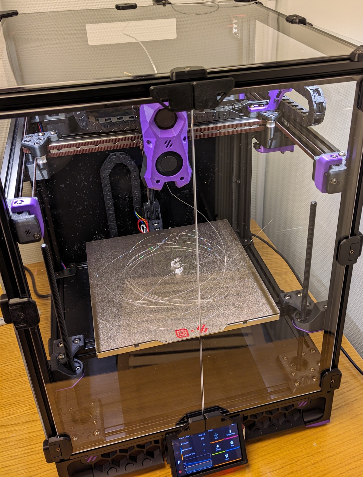
I’ve been busy.Busy printing stuff.

Which is awesome, because one big worry I had was if I’d actually use the printer or just end up modding and tweaking it until the end of time.

But of course, I’ve been slowly working through my large mods-I-want list.My initial plan was to write one blog post about modding, but for space and sanity reasons I’ve decided to split it up.

This post goes through a bunch of smaller fixes and mods I’ve done to the printer, and I’ll leave the more involved mods to later posts.

Tweaks & tuning

My plan was to take tuning seriously and go through all the tuning guides to get the printer to produce perfect prints. But I didn’t have patience for that and I’ve only made some tweaks when the prints had noticeable defects. Here are the major tweaks I’ve done since the last post:

Bed mesh offset in one corner

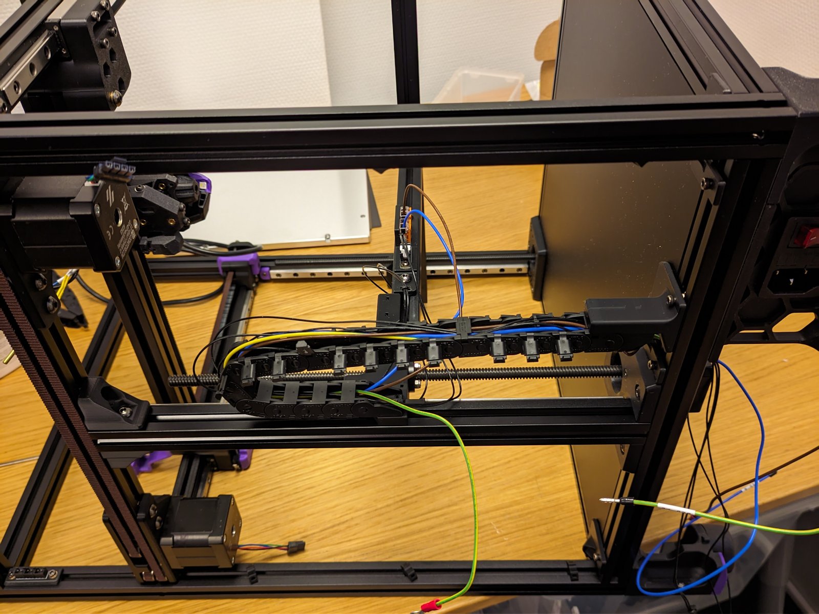
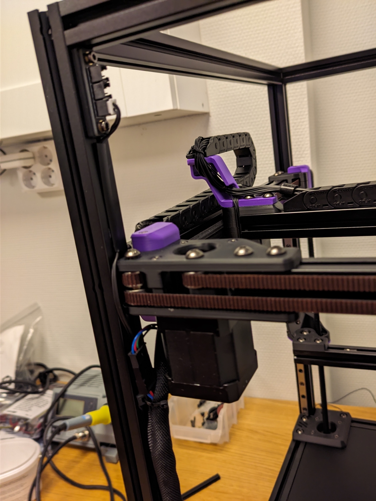
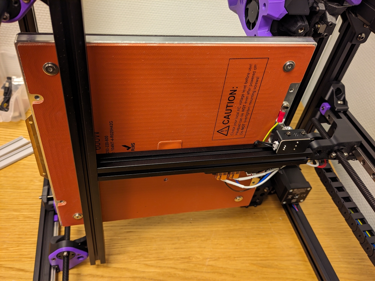
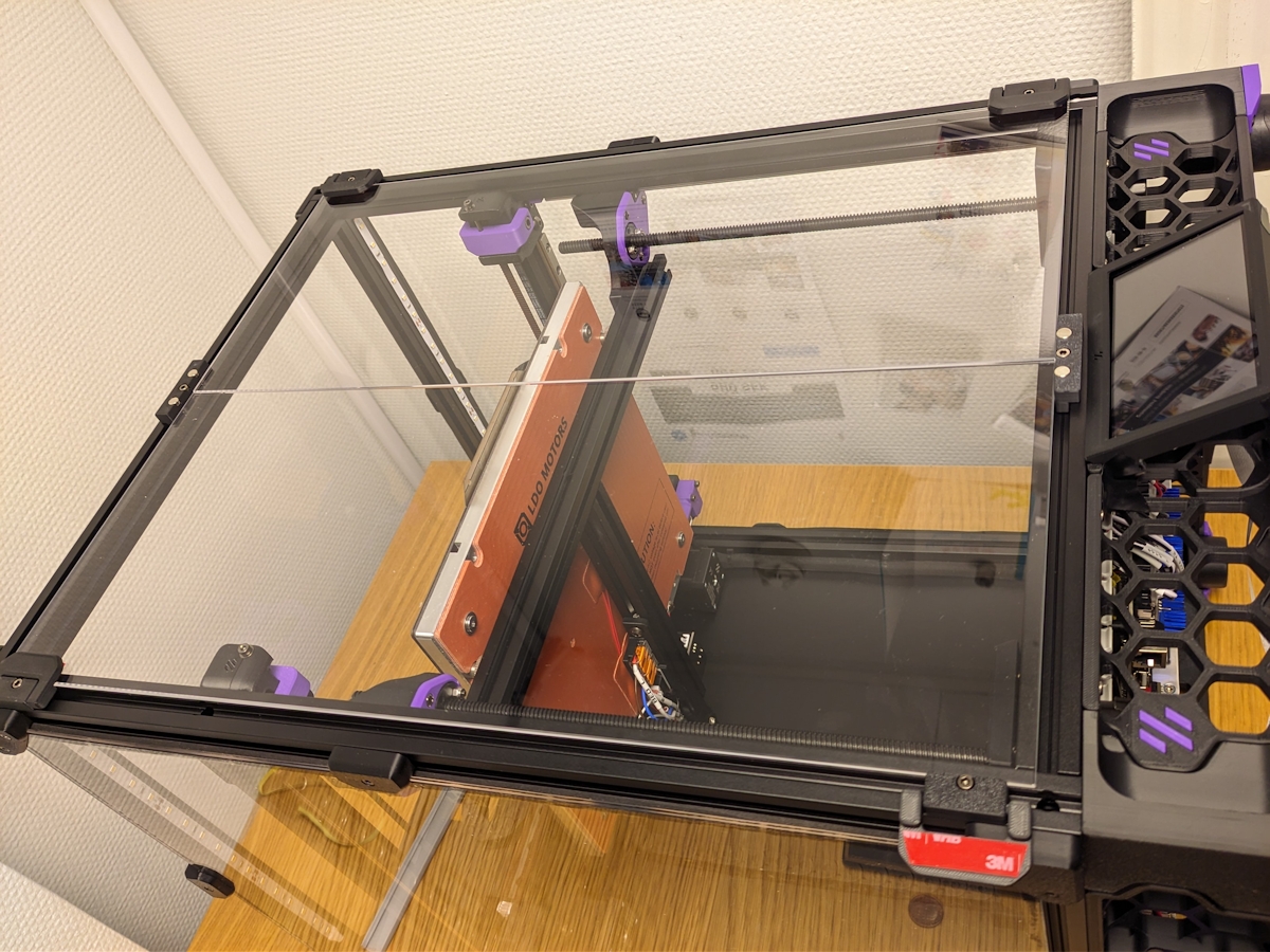
It got pointed out to me in the 
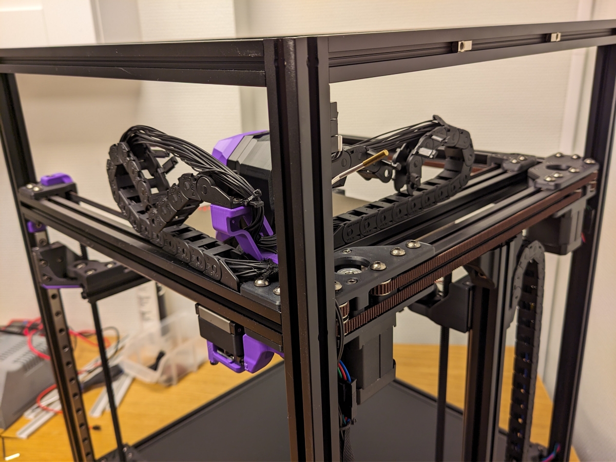
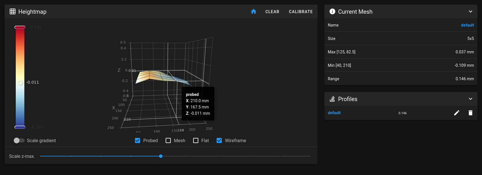
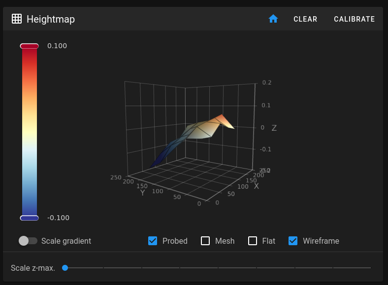
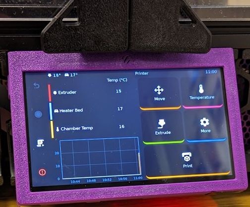
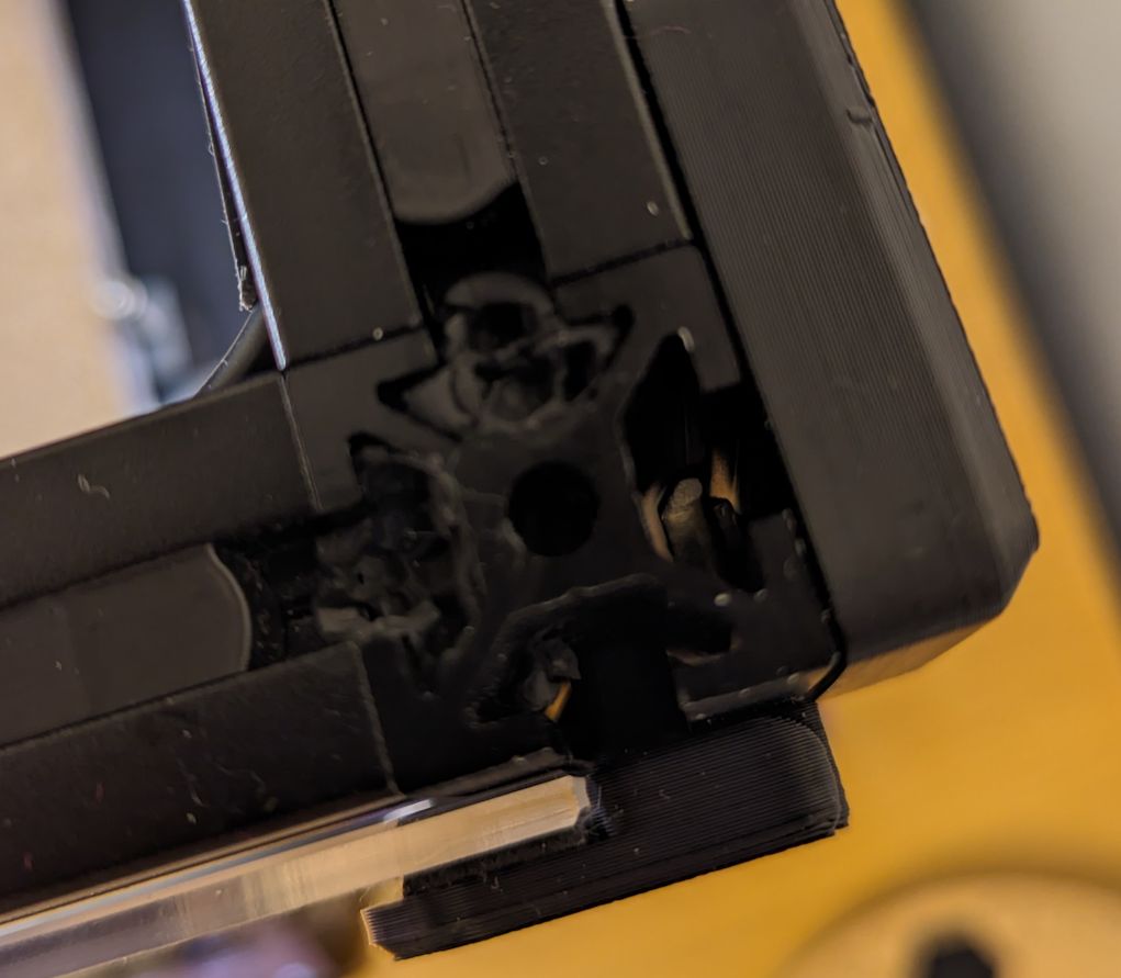
VORON forum that I my right rear Y extrusion was a bit high.The Trident has automatic bed leveling, but because the bed is only attached in three positions it can’t compensate for a difference in the rear that only has a single mount in the middle. If you’re unlucky this might cause issues with bed adhesion.

Turns out I’ve had some problems with bed adhesion. Not a lot mind you, but enough to bother me on some trickier prints.I’ve seen the offset on the corner go down to -0.26, which is more than the standard 0.2 layer height I use, so this might be the cause of some of the issues I’ve seen.

wonky_offset.png


Before adjusting the right Y extrusion.


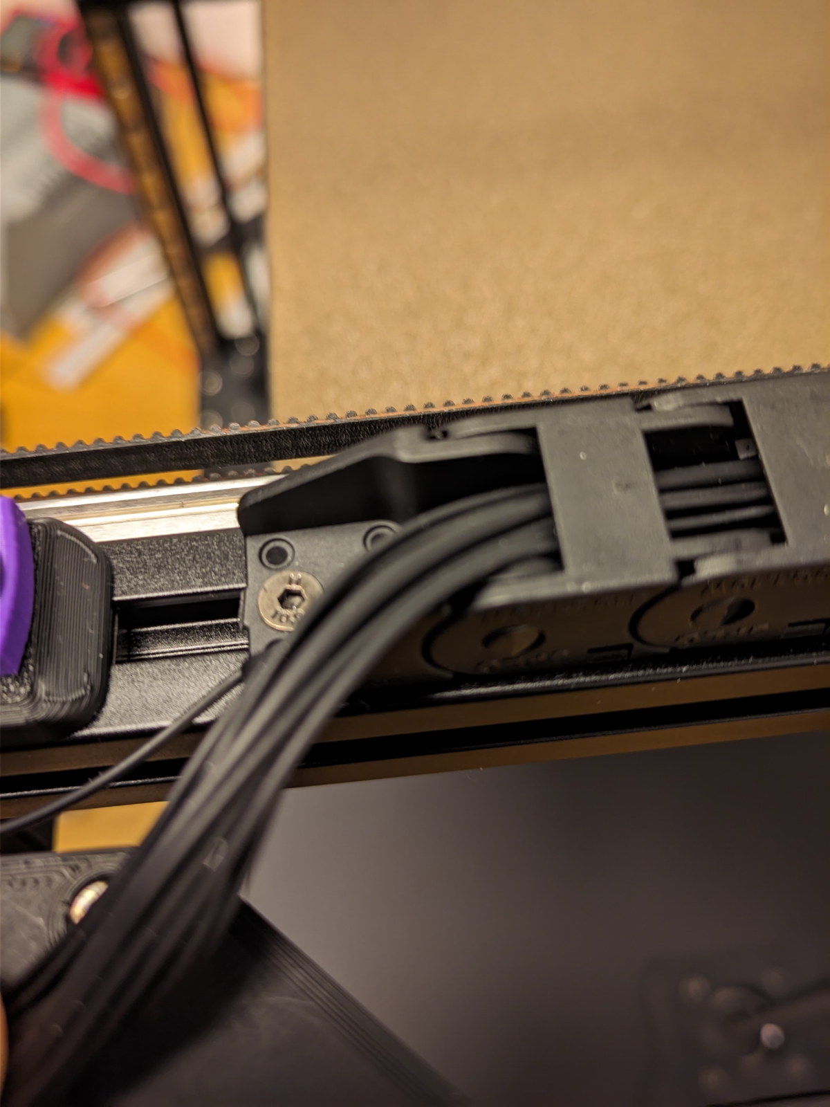
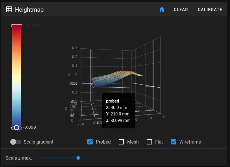
In the voron_1_trident_questions channel on the VORONDesign Discord there was a pinned message on how to adjust this.I ended up adjusting the front right Y extrusion upwards quite a bit to compensate for this.

mesh_fixed.png


After adjusting the front right Y extrusion upwards.

The mesh still isn’t perfect (and it can sometimes look worse than the adjusted picture above), but it’s now a lot better and importantly the rear corners are much more level.

Bulging corners


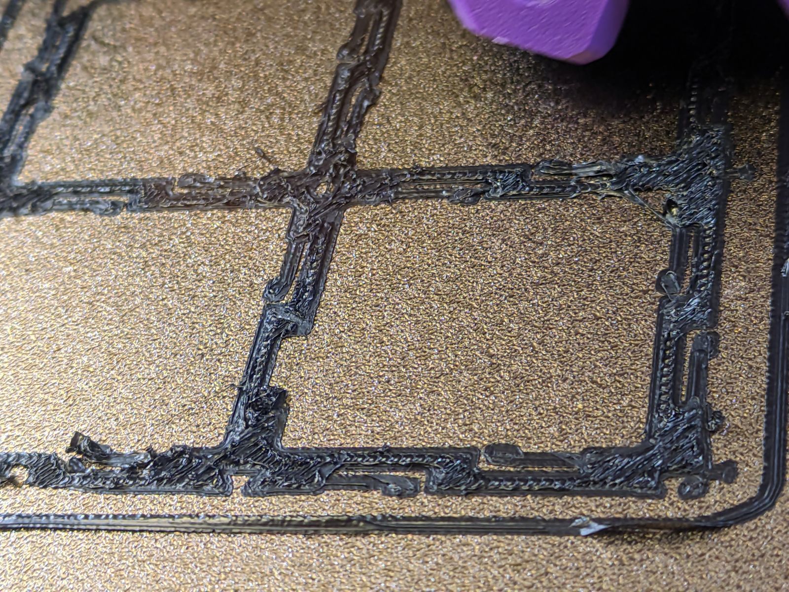
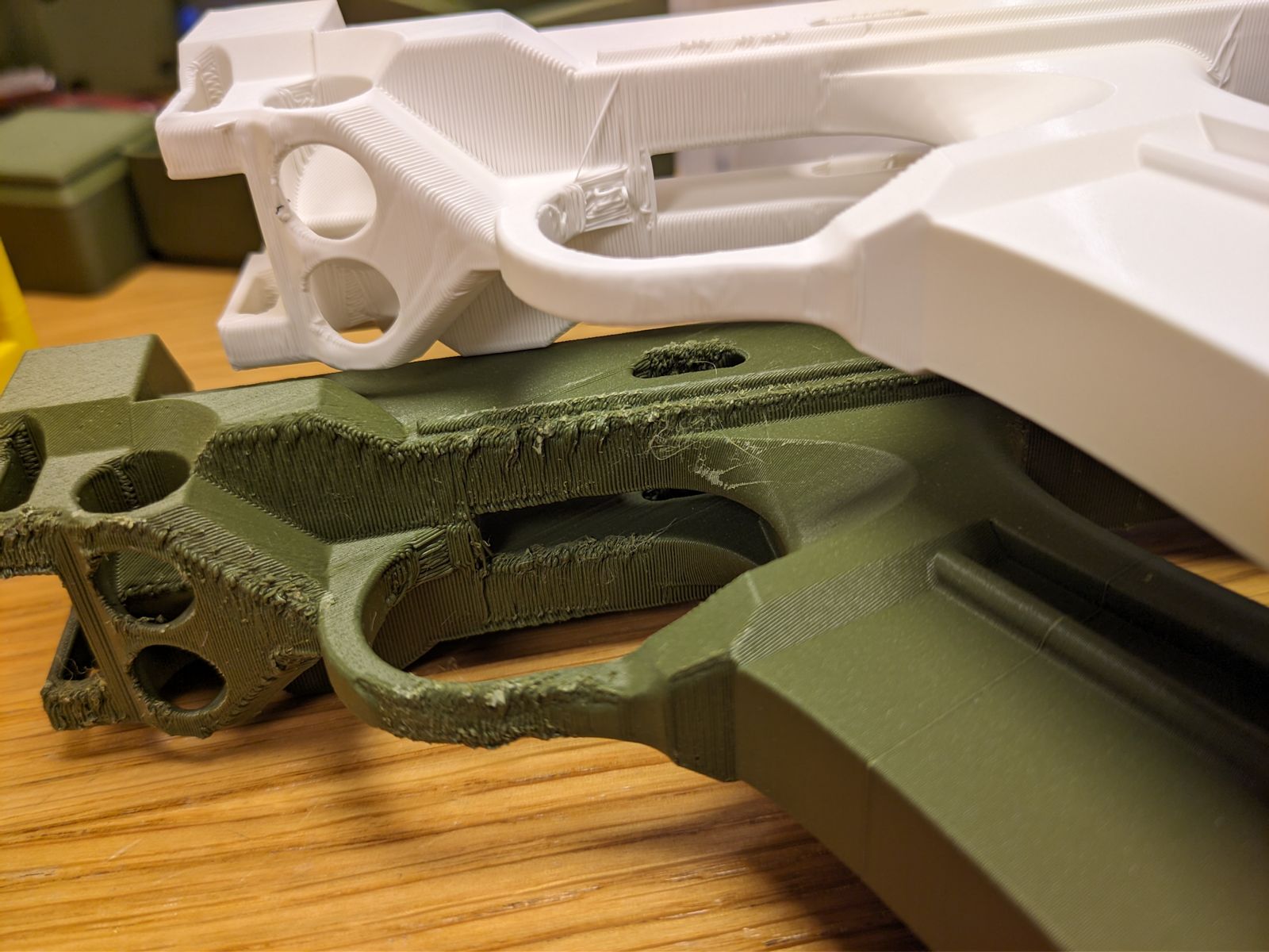
One significant print issue I’ve had is bulging in the corners on overhangs:

bulging_corners.jpg
Both edges round upwards and apart from being really ugly, they’ve caused a number of prints to fail when the nozzle has knocked loose pieces from the bed or has caused belts to skip.
bulging_black.jpg
It’s really ugly.

Maybe it was overheating? But it happened consistently, with long layer times, with max fans, and for PLA/ABS/ASA.Another idea was over extrusion, but I think that should’ve shown up in other places?
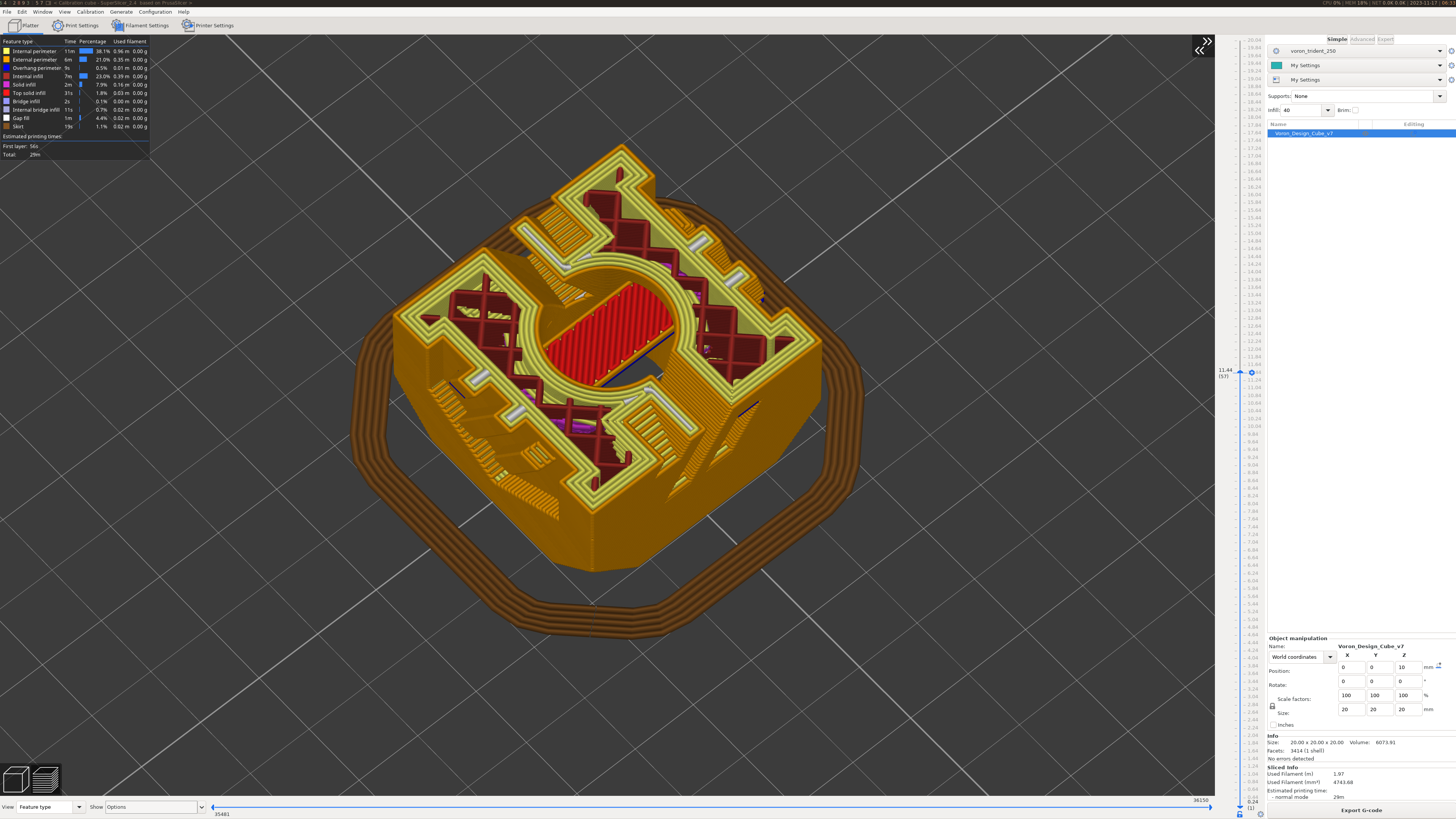
Then I found the Bulging section in Ellis’ Print Tuning Guide that made the issue disappear.These were the changes I made:
  • Enable external perimiter first
  • Set overhang threshold for bridge flow to 0
  • I also experimented with disabling overhangs specific settings completely (set bridge speed and fan to 0 or the disable checkbox), but I’m uncertain how effectual that was compared to the other two settings.
Some of these were specific to SuperSlicer, the slicer I use.

bulging_nerf.jpg
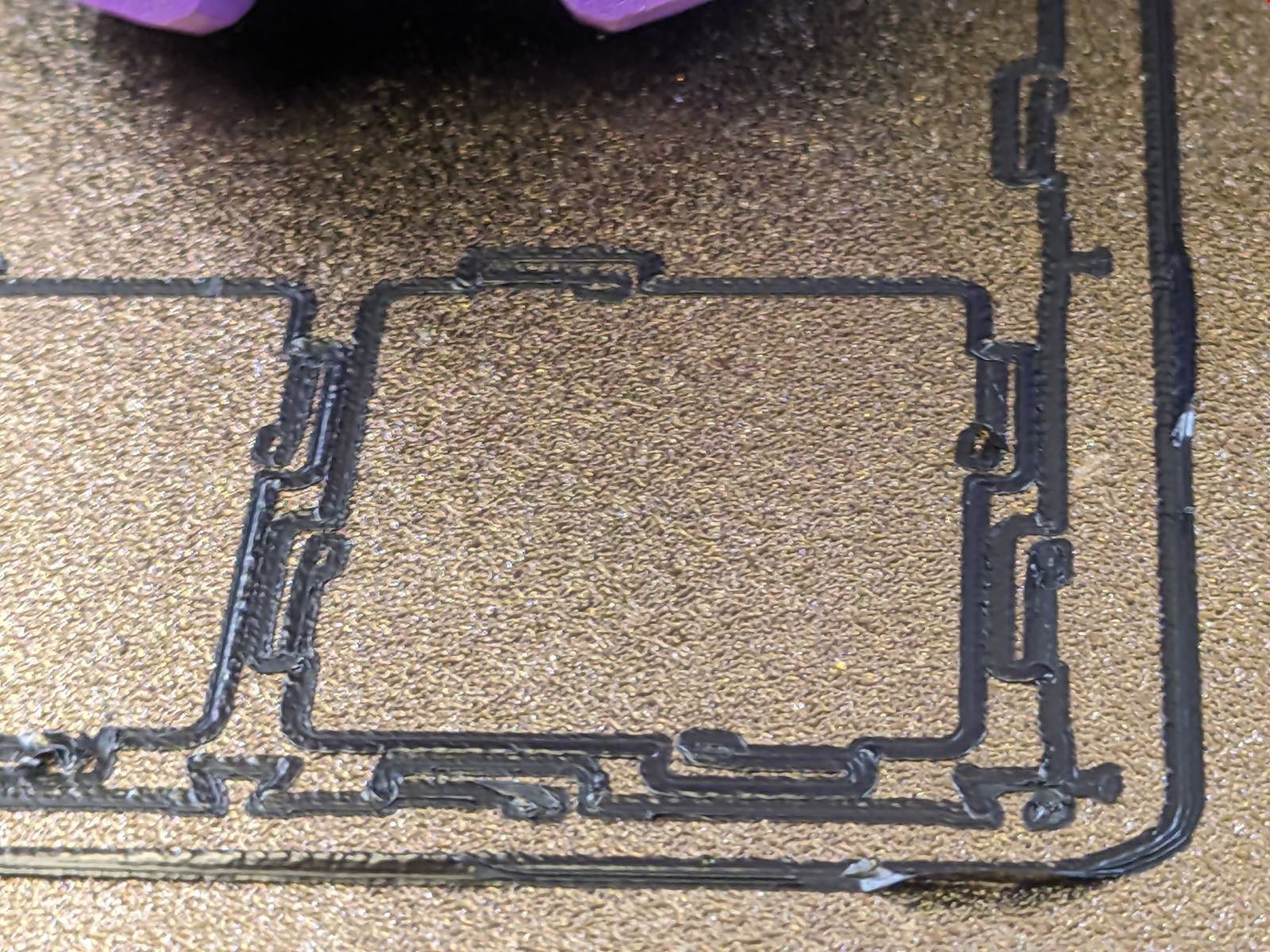
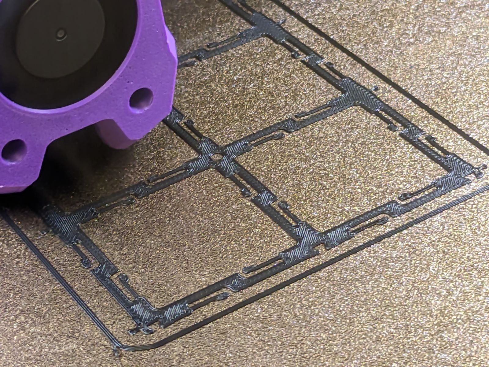
These are two prints that show the difference between the settings. The green is without the changes and white is with the changes.Apart from the overhangs, the green printout looks pretty good, but the overhangs look terrible. The white still has some defects, but it’s so much smoother.

Extruder skipping

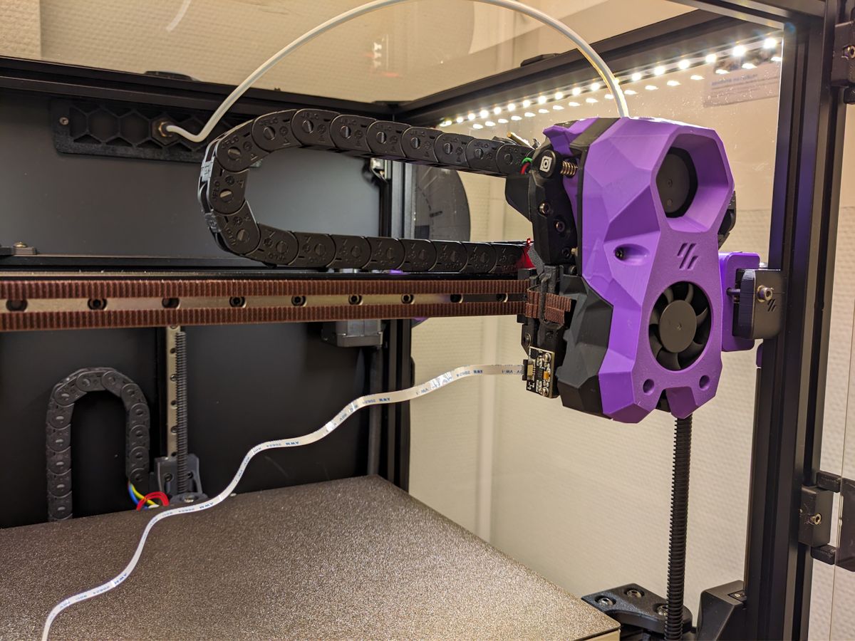
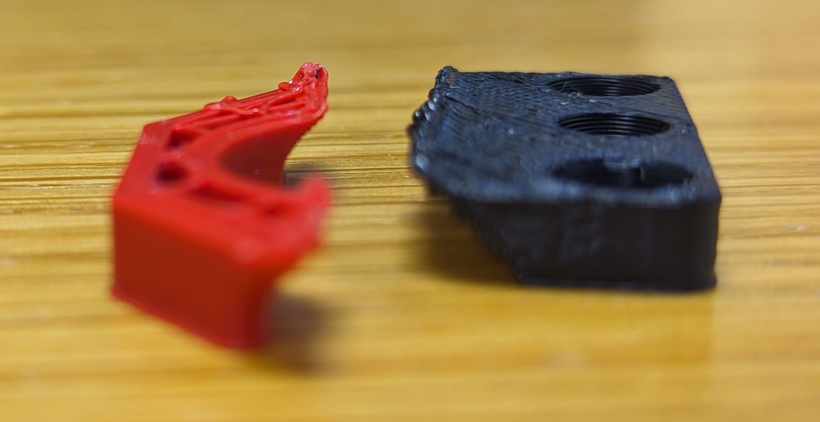
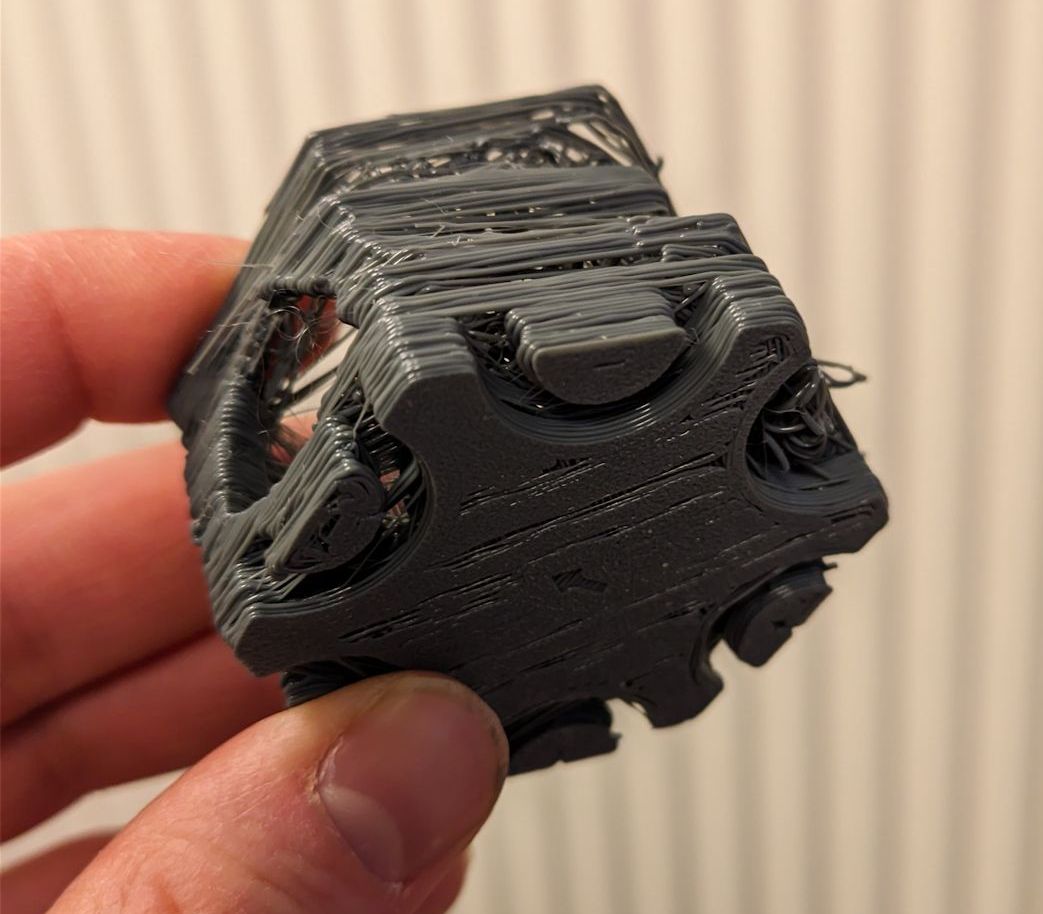
I had printed for around 400 hours when the extruder suddenly started skipping.At first it was just minor artifacts, but after a while prints started failing in major ways or refusing to extrude anything at all:

bad_skip.jpg

My first idea was that I had messed up the tension in the extruder, so it no longer got a good grip on the filament. (I had some major issues with loading filament at one time, and I started screwing around with everything I could think of.)

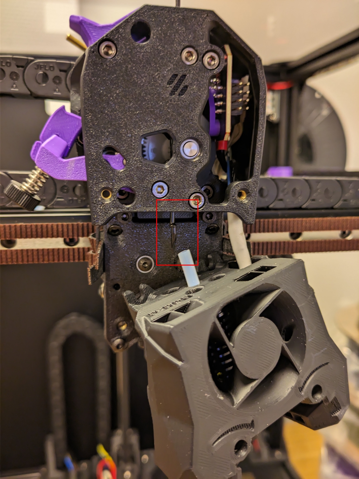
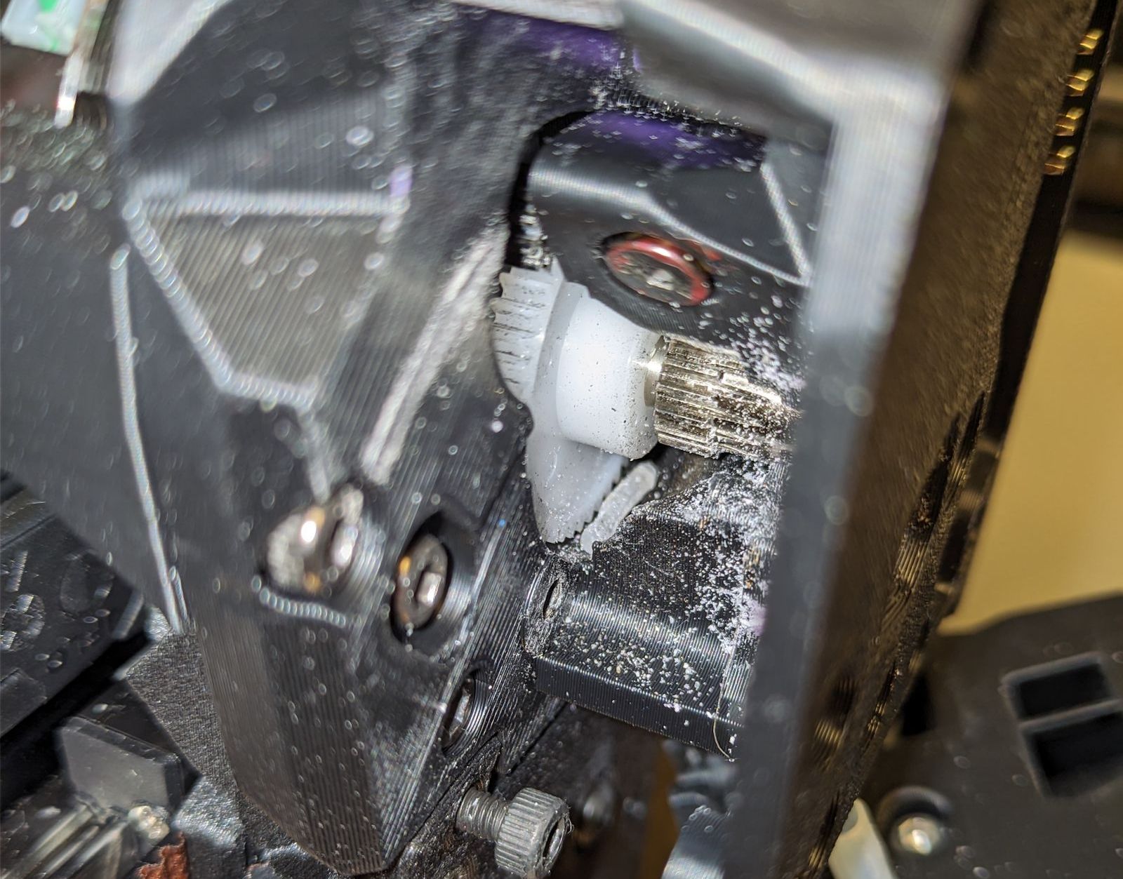
But alas I couldn’t solve it with a quick-fix, so I had to open up the toolhead. Which I should have done much sooner, because there were a bunch of broken filament stuck in the gears:

cw2_dirty.jpg
One piece of broken filament inside the CW2, together with a bunch of dirt.

I really didn’t want to disassemble it because I was afraid of the effort to do so, but in the end it was just a few screws and the whole cleaning process took 10 min. Building your own printer has some benefits, I should have more faith in the process.

2mm PTFE between extruder and hotend

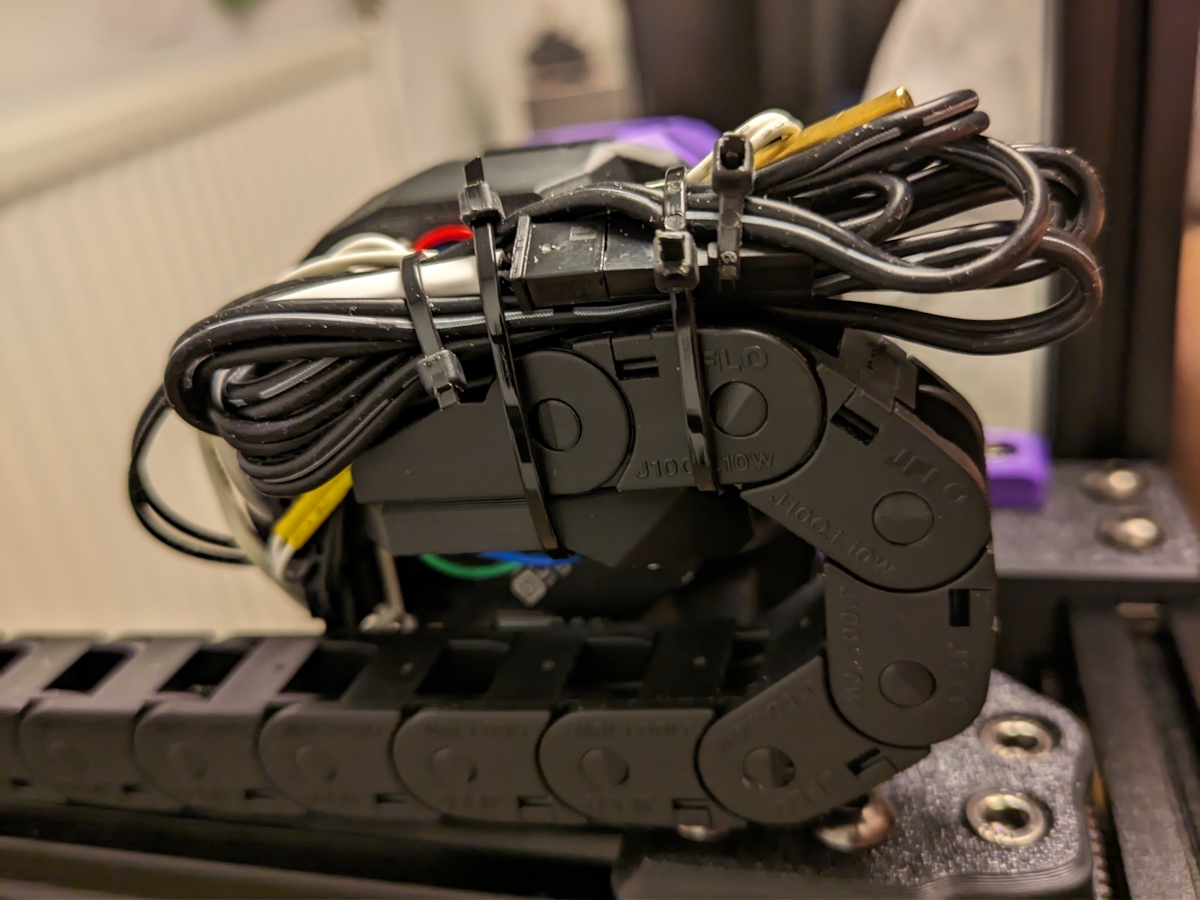
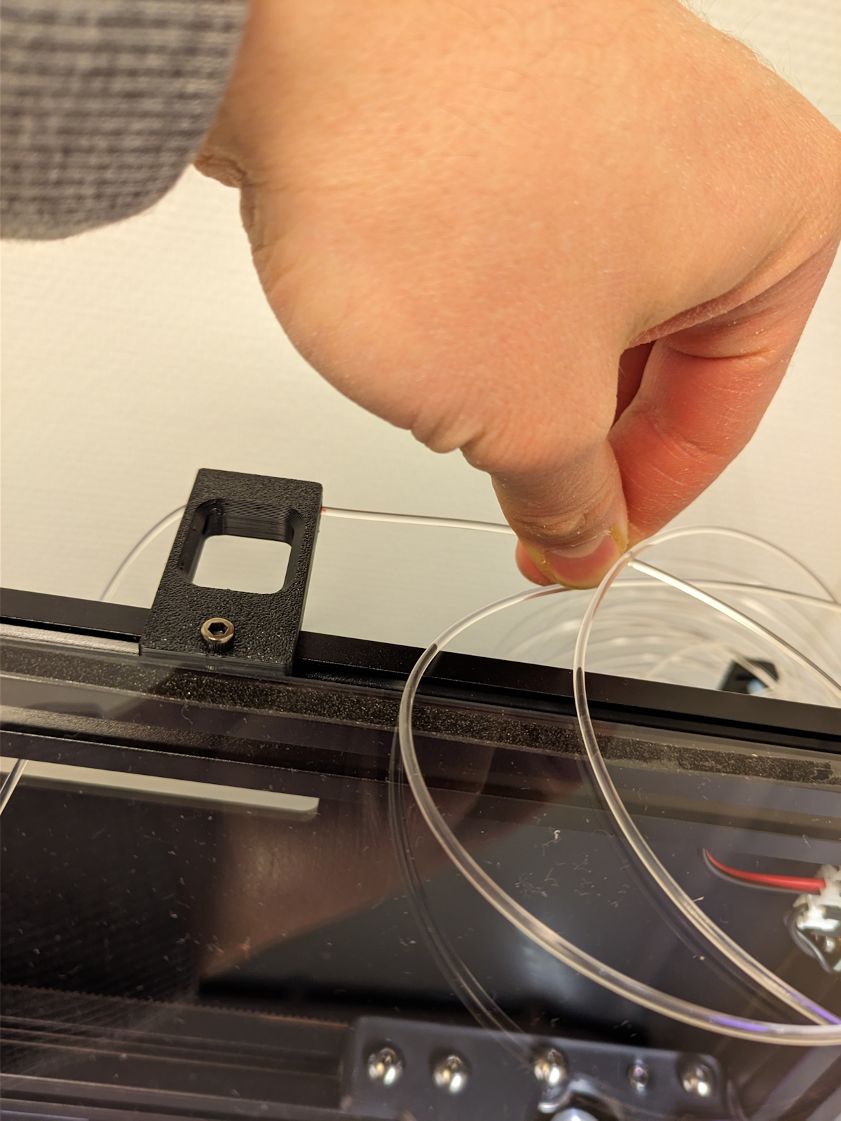
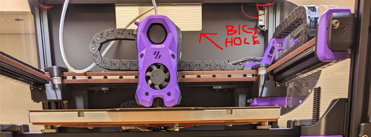
There were a lot of leftovers after the build; nuts, screws, belts, etc. But also an unused bag with “Teflon Tubing, 4x2mm”, which surely shouldn’t be completely unused?

Turns out you’re supposed to use a tube with an inner diameter of 2mm between the extruder and hotend, but I had used the regular PTFE tube that had an inner diameter of 3mm. This isn’t ideal and requires more retraction (which I didn’t compensate for), and it can cause stringing issues (which I had).

Note to self: Don’t use a tube with an inner diameter of 2mm between the extruder and spool, the filament will get stuck due to friction.

First layer woes


For a long time I was really happy with how my first layers looked and I could start a print and it would finish without issue most of the time.

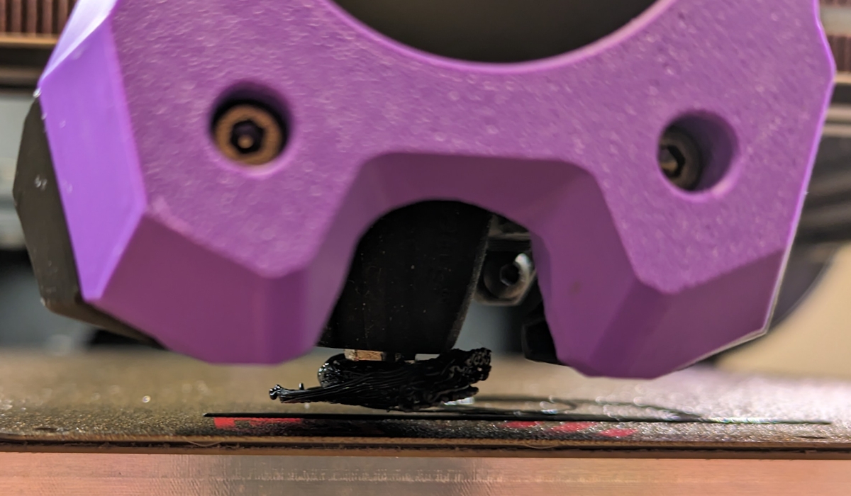
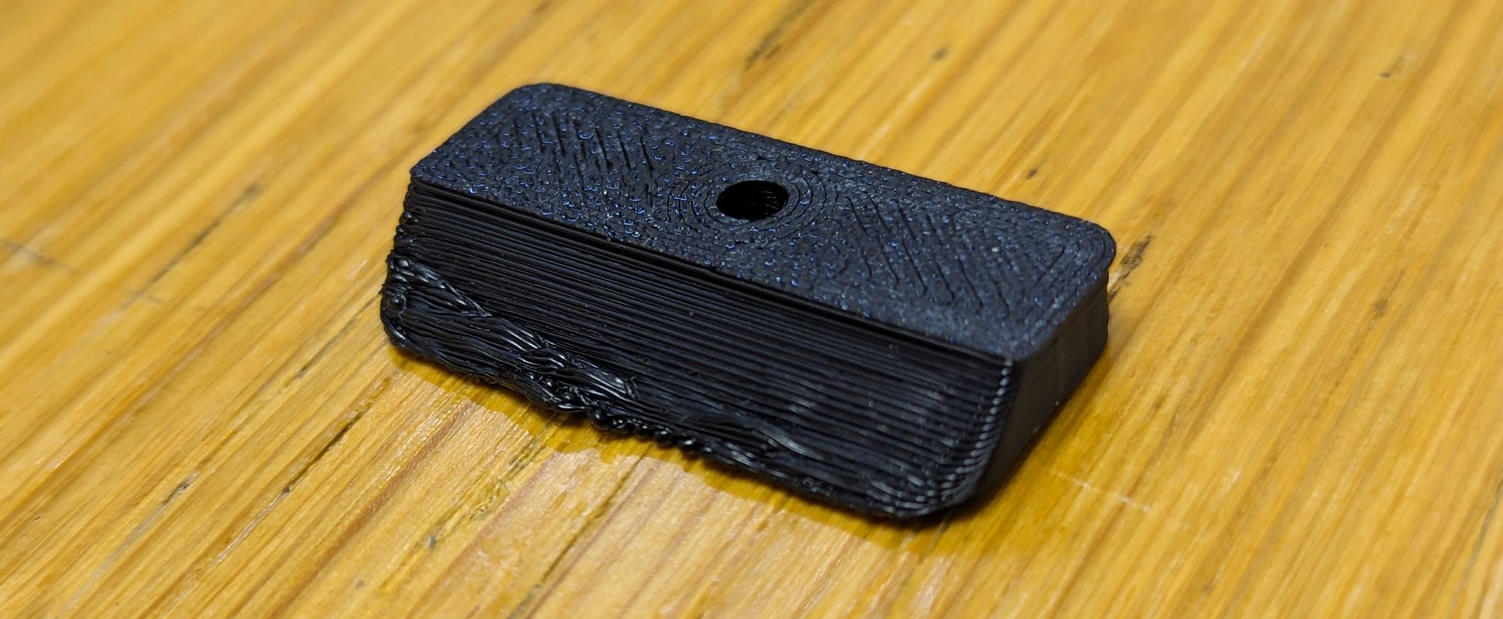
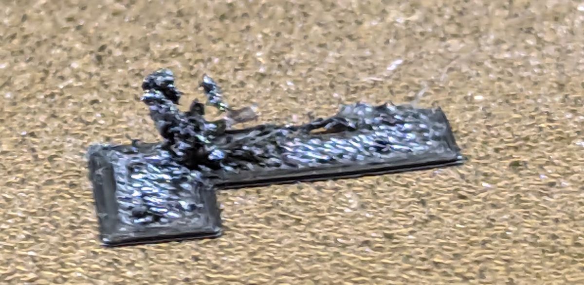
But sometimes I had these “blobs” that started collecting:

filament_blob_printing.jpg
This is some extra filament that has been pushed around and gotten stuck on the print.

I couldn’t figure out where it was coming from. Overextrusion maybe, but i didn’t find any issues with it and this only happened in the beginning of the print.

And later on I started to get severe issues with bed adhesion where I felt lucky if a part stuck around long enough for the print to finish.The first layer started to look garbage as well:


The worst part is, I didn’t think I had changed anything.

In hindsight me fixing the bed mesh offset might have been the cause my sudden problems.

I tried a bunch of things; changing nozzle, recalibrating PA and EM, changing filament, and even replacing the extruder (more on that in a future post) yet the issue remained.

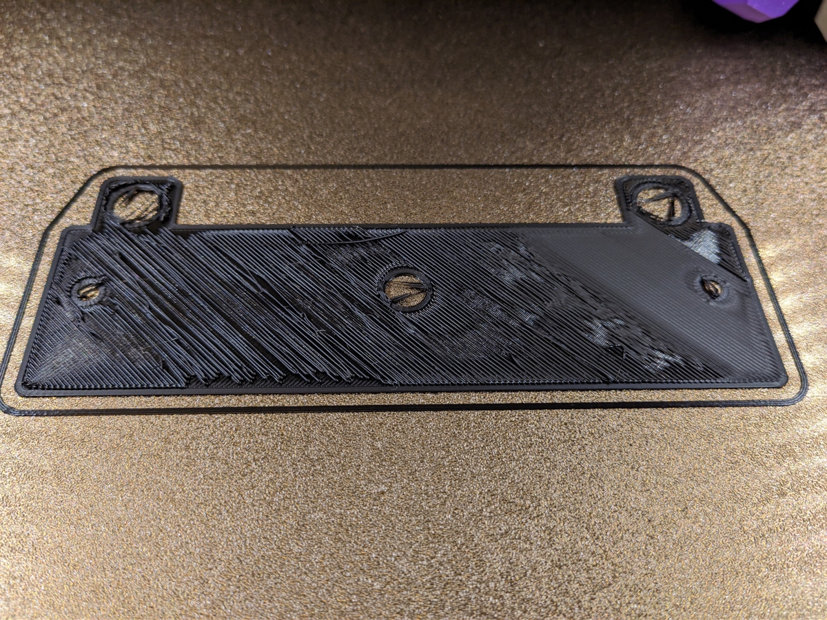
What finally fixed it was recalibrating the z offset and tuning first layer squish once more. I’m not sure why I had to do this again (doesn’t Tap magically solve everything?), but now the first layer is pretty and the bed adhesion problems are almost completely gone. (Some prints have a tendency to warp a little, but I guess it’s hard to get things perfect.)

clickfinity_good.jpg
Much better first layer!
 
Part 8b


Mods

These are some smaller mods from the LDO kit I hadn’t gotten around to installing, and some other small mods that fixed some annoyances I’ve had.

Handles

handles.jpg

The kit includes some very nice handles you can install. But unfortunately they cover up the top panel so you have to remove the handles before you can remove the panel—a gigantic pain.

So I ended up printing some sturdy handles instead. They’re really large comparatively, but they get the job done.I haven’t had that much use for them yet, but I felt obliged installing them since some kind of handles came with the kit.

LED mounts


There were no instructions on how to install the LEDs, so I taped them on top of the included extrusions covers. Turns out you were supposed to print a bunch of LED mounts to get the LEDs pointing inwards towards the print for better lighting:

led_old.jpg
Before the LED strips were mounted flat.
leds_installed.jpg
Now they’re tilted inwards and have shields to direct the light towards the build plate.

Longer spool holder

longer_holder.jpg
The stock spool holder to the left, a longer one I printed to the right.

I ran into the surprising issue that some spools were too wide for the stock spool holder (3DJake’s filament for example).So I replaced it with a longer one.

In the future I should probably replace it with a top mounted spool holder, but I got lazy when I saw I didn’t have the required M5 hardware. Maybe another day.

Bowden tube routing

bowden_tube_routing.jpg

I had some issues with the bowden tube getting stuck behind or under the cable chain, so I tried the bowden tube guide to keep it away .It was difficult to find a route that worked well. Depending on the mount position it had a tendency to cause a bend in the tube that drastically increased the friction on the filament, which I suspect was the cause for some prints failing.

I also use the Trident noodle that’s made to prevent the tube from colliding with the roof of the printer, and this combination works very well.
noodle.jpg

Display mount

display.jpg

The display mounts I got from the print-it-forward service wasn’t compatible with the screen I got, so I had to hold it together with tape.

So I tried to find the proper parts to print, but I must be missing something because the screw holes to hold the display cover still don’t line up. I don’t care to spend more energy on this; it’s a bit weird but tape does the job well enough.

At least I got the display cover in an accent color.

Improved seal in extrusions

sugru.jpg

Despite having the Nevermore filter and a HEPA filter exhaust, I could very clearly smell ABS fumes from the printer.Looking at the extrusions, there were large holes in the blind joints and I suspect that doesn’t help.

Therefore I tried to cover up the holes with some Sugru. It’s better, but I should probably replace the front door too.

Are we done yet?

It’s true that the printer can now be considered Done™—and it has been done for a while—but I still have some mods I’d like to document before I wrap up this build series.
 
No. You are never done. :LOL: I built my Trident...um, 3 years ago now?! I just replaced the CW2 with a Galileo2 on it. There's always something else to tweak or play with. Eventually maintenance or mishaps will make you get in there with the wrenches and take things apart again. It's all part of the fun.
 
Yeah... I've already done a fair share of mods but I plan to do a few more before the next roundup post.

But I've also looked at some "big" mods like XOL and multimaterial... But I've noticed a fatal flaw:

I only have one printer!

So I should get a VORON 0 soon... And I guess get stuck modding that instead.

Yikes.
 
Top