dancingborg
Member
Hi Voron community, seeking help getting my Tap wired up. I tried on Discord and have since attempted recommended investigations by a kind user, but do not know where to go from there.
Pre-Existing (Working) Setup
(This is where I become confused)
Pre-Existing (Working) Setup
- LDO 2.4r2
- LDO Afterburner Toolhead PCB (Github link)
- LDO Afterburner Breakout PCB (Github link)
- BTT Octopus Board (Github link)
- LDO Klicky Kit
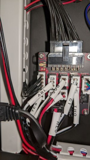
- Klicky JST plugged into Toolhead PCB PROBE header: GND & S (picture of board)
- Standard LDO wiring heeding caution of reversed wiring between breakout PCB plug and mainboard plug at J34/DIAG7: GND & PG15 ("different pinout")
- So as far as I can tell, following the wires Klicky was effectively plugged into PG15 & GND at J34
- Probe Config
YAML:[probe] pin: PG15
- I soldered an Optotap V1 PCB, given it 5V from a breadboard. The red LED lights up and turns off when something is passed through the sensor port. (I believe this is correct functionality). It was initially giving some inconsistent readings but I noticed the sensor housing was wobbly (solder points were solid) so I applied two dots of super glue to bond the sensor housing to the PCB. It seemed to be working reliably.
- My LDO kit had a seperate Stealthburner LED loom for 5V/SIG/GND. I forked the 5V and GND, and added DuPont headers to that I could grab 5V from there.
- I plugged by Optotap PCB into the forked Stealthburner 5V/GND, and it again appeared to be working reliably including when mounted in its final position with the Tap toolhead installed.
- Thus the remaining task was to connect the Optotap signal pin to the mainboard via the LDO Afterburner Toolhead and then Breakout PCBs.
- I put the Optotap signal output into a JST connector and plugged it into the Afterburner Toolhead PCB PROBE at position S, figuring it was most like what Klicky was doing. This caused the Optotap red LED to turn off permanently regardless of toolhead being up or down.
- I put the Optotap signal output into the PROBE header at position GND. This caused Optotap red LED to turn on permanently regardless of toolhead being up or down.
- I then checked and noticed that when multimeter probing the Stealthburner LED GND and PROBE S pin, there was a 3.3V signal that (excuse my poor electronics knowledge) seems to be coming out of this pin, perhaps contributing to it not being a good choice.
- As mentioned, I referred it to the Tap channel on Discord, where someone recommended I chase down the wiring with a multimeter, which I did and will clarify below.
- Cable with sleeve label ABL on Breakout PCB has corresponding end labelled Z Probe on the mainboard, and there is continuity:
- Between (white) ABL pin on PCB and PG15 on the mainboard.
- Between (black) GND pin on PCB and GND of J34 on the mainboard.
- On the main loom, there is continuity between the ABL pin on the Breakout PCB and the Toolhead PCB
(This is where I become confused)
- On the toolhead PCB, there is no continuity between the loom header ABL pin and the PROBE header S pin.
- Klicky, via LDO Toolhead and Breakout PCB, appears to have been wired to Octopus J34 GND & PG15, yet a signal from Optotap doesn't seem to work in the same setup.
- I'm just another guy trying to get Tap to work and have somehow got as far as I have with as little electrical knowledge as I have
- I think I have all the data I need as I have located all the relevant resources and schematics, but just can't reach the understanding needed to resolve this
- I am happy to plug any cable anywhere to make Tap work, and have plenty of JST crimping parts to plug the Optotap signal pin anywhere
- I am unfortunately still tied to the LDO PCBs, but from my reading of Discord, it seems there ought to be a way to make it work


