What's new
VORON Design

Register a free account today to become a member! Once signed in, you'll be able to participate on this site by adding your own topics and posts, as well as connect with other members!

Solved Tap Wiring with LDO Afterburner PCB

dancingborg

Member
Hi Voron community, seeking help getting my Tap wired up. I tried on Discord and have since attempted recommended investigations by a kind user, but do not know where to go from there.

Pre-Existing (Working) Setup
  • LDO 2.4r2
  • LDO Afterburner Toolhead PCB (Github link)
  • LDO Afterburner Breakout PCB (Github link)
  • BTT Octopus Board (Github link)
  • LDO Klicky Kit
    • Klicky JST plugged into Toolhead PCB PROBE header: GND & S (picture of board)
    • Standard LDO wiring heeding caution of reversed wiring between breakout PCB plug and mainboard plug at J34/DIAG7: GND & PG15 ("different pinout")
    • So as far as I can tell, following the wires Klicky was effectively plugged into PG15 & GND at J34
  • Probe Config
    YAML:
    [probe]
    pin: PG15
Preparatory Work
  • I soldered an Optotap V1 PCB, given it 5V from a breadboard. The red LED lights up and turns off when something is passed through the sensor port. (I believe this is correct functionality). It was initially giving some inconsistent readings but I noticed the sensor housing was wobbly (solder points were solid) so I applied two dots of super glue to bond the sensor housing to the PCB. It seemed to be working reliably.
  • My LDO kit had a seperate Stealthburner LED loom for 5V/SIG/GND. I forked the 5V and GND, and added DuPont headers to that I could grab 5V from there.
  • I plugged by Optotap PCB into the forked Stealthburner 5V/GND, and it again appeared to be working reliably including when mounted in its final position with the Tap toolhead installed.
  • Thus the remaining task was to connect the Optotap signal pin to the mainboard via the LDO Afterburner Toolhead and then Breakout PCBs.
First Attempts
  • I put the Optotap signal output into a JST connector and plugged it into the Afterburner Toolhead PCB PROBE at position S, figuring it was most like what Klicky was doing. This caused the Optotap red LED to turn off permanently regardless of toolhead being up or down.
  • I put the Optotap signal output into the PROBE header at position GND. This caused Optotap red LED to turn on permanently regardless of toolhead being up or down.
  • I then checked and noticed that when multimeter probing the Stealthburner LED GND and PROBE S pin, there was a 3.3V signal that (excuse my poor electronics knowledge) seems to be coming out of this pin, perhaps contributing to it not being a good choice.
Referral to Discord
  • As mentioned, I referred it to the Tap channel on Discord, where someone recommended I chase down the wiring with a multimeter, which I did and will clarify below.
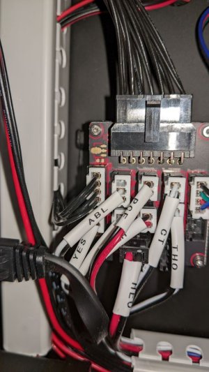
  • Cable with sleeve label ABL on Breakout PCB has corresponding end labelled Z Probe on the mainboard, and there is continuity:
    • Between (white) ABL pin on PCB and PG15 on the mainboard.
    • Between (black) GND pin on PCB and GND of J34 on the mainboard.
  • On the main loom, there is continuity between the ABL pin on the Breakout PCB and the Toolhead PCB
Limit of my Understanding
(This is where I become confused)
  • On the toolhead PCB, there is no continuity between the loom header ABL pin and the PROBE header S pin.
  • Klicky, via LDO Toolhead and Breakout PCB, appears to have been wired to Octopus J34 GND & PG15, yet a signal from Optotap doesn't seem to work in the same setup.
Summary
  • I'm just another guy trying to get Tap to work and have somehow got as far as I have with as little electrical knowledge as I have
  • I think I have all the data I need as I have located all the relevant resources and schematics, but just can't reach the understanding needed to resolve this
  • I am happy to plug any cable anywhere to make Tap work, and have plenty of JST crimping parts to plug the Optotap signal pin anywhere
  • I am unfortunately still tied to the LDO PCBs, but from my reading of Discord, it seems there ought to be a way to make it work
So here I am, and if you got this far, thank you for your patience and any wisdom you might be able to provide to help a fellow maker.
 

Attachments

  • PXL_20230404_032837369_2.jpg
    PXL_20230404_032837369_2.jpg
    92.3 KB · Views: 132
  • PXL_20230404_032845313_2.jpg
    PXL_20230404_032845313_2.jpg
    121.1 KB · Views: 125
  • PXL_20230404_065117449_2.jpg
    PXL_20230404_065117449_2.jpg
    104.7 KB · Views: 125
After some further investigation, I found that the two below changes made it all work.
  • Change from:
    YAML:
    [probe]
    pin: PG15
  • To the below adding the enablement of the internal pullup sensor:
    YAML:
    [probe]
    pin: ^PG15
  • Also removed the GND pin from the middle of the J37 plug, so that the only pin present on the J37 plug is PG15, which is pulled up in config (see above).
  • Put the loose GND pin into a spare JST (or whatever it is) plug so it couldn't accidentally short anything by dangling around
Have since successfully completed post-install steps and QGL, so it looks to be working well enough now.

If you found this useful, or found a better way to accomplish what I did, or can explain why it works, please consider adding your reply here.

Take care.
 
After a few successful prints this solution stopped working. I also tried applying a pull-down to PG15 but this didn't work either. Unless I post a further reply please do not take my solution as working. Hoping to update this thread when I manage to get to the bottom of it, or at least further down the road.

At this time it appears to do with the BAT85 diode being used on the PCB to either allow or not allow back-current from PG15, and the mainboard reading state from the back-current it feeds in. Official documentation below:

Due to the switching used by the sensor the output voltage is approximately the same voltage as the sensor is powered with. If the sensor is powered with the common 24V, it will send 24V to an input on the MCU that is never intended to see more than 5V. The BAT85 diode is used to alleviate this issue. It is oriented so that when the probe signal wire is high (12-24V), not current will flow into the MCU input pin. As a result the MCU will read HIGH voltage due to the internal pull-up resistor. If the probe signal is LOW (0V), current will flow from the MCU input pin through the diode, through the probe, and to ground (V-). This will pull the MCU pin low and trigger appropriately.

So now that means that it makes sense for the PG15 pin to be outputting 3.3V (although I hadn't had it pulled up at the time). It also makes sense that the Optotap is not able to push 24V out to override the 3.3V back-current and thus cause the PG15 pin to change state.

I also tried using the GND from the Toolhead PCB Probe header, but this made no difference. So to summarise the things that did not appear to work:

  • Disconnecting GND from PG15
  • Applying pull-up to PG15 with GND disconnected
  • Applying pull-down (~) to PG15 with GND disconnected
Things I might try:

  • Throwing money at the problem and ordering a 24V PCB (although if it's just a greater input range and the output doesn't change this might not work)
  • Reconnecting GND to PG15 so that the pull-up and pull-down might work better
 
Further progress. Useful information on Discord from Esoterical:
When the led is lit, signal will be pulled to gnd. When led is off (which is when tap is lifted ie. Triggered) the signal is floating which due to pull-up resistors will be pulled to logic high (likely 3.3v)
Conducted further tests:
  • With ^PG15 (pull-up):
    • (Sanity check) The toolhead Probe header 24V pin reads 24V when grounded against LED GND or Probe header GND
    • The toolhead Probe header S pin reads 3.3V when grounded against LED GND or Probe header GND
    • The Optotap LED is in fact still lit, but only very dimly, and still behaves correctly, being on for down and off for up over repeated cycles
    • Klipper reports Endstop Z (and hence Probe) Triggered reglardless of Tap being up or down
  • With ~PG15 (pull-down):
    • (Sanity check) The toolhead Probe header 24V pin reads 24V when grounded against LED GND or Probe header GND
    • The toolhead Probe S pin reads 2.6V when grounded against toolhead GND
    • The toolhead probe S pin reads -1.5V when grounded against toolhead 5V
    • The Optotap LED is in fact still lit, but only very dimly, and still behaves correctly, being on for down and off for up over repeated cycles
    • Klipper reports Endstop Z (and hence Probe) Triggered reglardless of Tap being up or down
  • With PG15 (neither pull-up nor pull-down) seems to work
    • (Sanity check) The toolhead Probe header 24V pin reads 24V when grounded against LED GND or Probe header GND
    • The toolhead Probe S pin reads 3.3V when grounded against toolhead GND
    • The toolhead probe S pin reads -1.5V when grounded against toolhead 5V
    • The Optotap LED is fully lit and behaves correctly, being on for down and off for up over repeated cycles
    • Klipper reports Endstop Z not triggered when in down position
    • Klipper reports Endstop Z triggered when Tap is in raised position and Optotap LED is turned off
For now, it appears that PG15 in raw state with GND disconnected at the mainboard is working. Will report back after a few days and mark resolved if so.
 
Update. Continued use of PG15 without pull-up or pull-down seems to be working semi-reliably. Still occasionally hangs in the triggered state, but eventually becomes responsive again and, overall, works most of the time.

Long term solution is the purchase of a 24V board to hopefully alleviate this issue, which I believe remains to do with the BAT85 diode between the sensor signal and the mainboard.
 
Last edited:
Further longitudinal testing seems to suggest that number of effective Tap probes is proportional to time spent with LED fully illuminated, that is, the more Tap probes are done in succession the higher the likelihood of the LED going into 'low power mode'. Only constant is that with pull-down Klipper detects the probe as triggered at all times.
 
Some corollary information I was not able to capitalise on was also given recently by a Discord user below (link):

08:13 Azi V2.4971:

I think that's usually a floating ground thing.

I also found this somewhat relevant thread on Github about PB7 pins, 4k7 resistors and BAT85 diodes, but ultimately I was not able to make use of the information I found.

I also posted this video in Discord of the problematic behaviour, but I cannot post the video filetype in this forum so a link is the best I can do.

Most repeatable behaviour thus far is wait >60mins for Optotap LED to become fully illuminated again, then can successfully home XYZ (only 2x Z-Probe cycles), but always fails a QGL with the LED going dim.

While I wait for a V2 Optotap PCB my suggestion to anyone reading is to have Unklicky Tap ready to go just in case your PCB options don't work. Unklicky Tap is electrically much simpler so might not be subject to the issues I am experiencing. I should say however that I have not verified this solution. Will post an update with Optotap V2.X (not yet confirmed which version exactly I'm getting) and also will test with Unklicky Tap as well.
 
After no luck with a V1 Optotap PCB with any PG15 in either vanilla, pull-up or pull-down, I ended up ordering and receiving a V2 Optotap PCB. Notably this PCB was V2.1 with known inrush voltage issue and not the most recent Optotap V2.4.1. V2.1 was however shipped from Orvil3D (see listing) with a resistor in the wiring harness, presumably supplied according to this interim solution to the known Github issue here, to alleviate this issue. Subsequent use of the V2.1 PCB with inline resistor has successfully passed G28 and QGL, which V1 PCB could not.

It should be noted that as I soldered the V1 PCB myself, all of the above could be due to user error of soldering the PCB including soldering the sensor onto the PCB.

Currently awaiting on vendor to see if any pull-up or pull-down modifiers should be used with the PG15 pin.

Vendor confirms the inline resistor wiring harness ships this way from Fysetc and does indeed contain a 2.2 ohm resistor.
 

Attachments

  • PXL_20230417_051959964.jpg
    PXL_20230417_051959964.jpg
    931.1 KB · Views: 105
  • PXL_20230417_053042420.jpg
    PXL_20230417_053042420.jpg
    518.6 KB · Views: 106
  • PXL_20230417_053347950.jpg
    PXL_20230417_053347950.jpg
    618.3 KB · Views: 133
Further follow up regarding software config. I had asked whether Optotap required any pull-up or pull-down in software/config, mainly due to Unklicky Tap mentioning a pull-up here. Discord user Dragonkitty said:

18:21]Dragonkitty ▞ replimat.eu:

no, the Octopus has hardware pullups on the endstop pins

This answer explains why I seemed to get the same results peviously whether or not I enabled the config pull-up.

So as a result, my abridged config is PG15 with pull-up enabled as a reminder of the hardware pull-up that is always present (as far as I can tell):

YAML:
[probe]
pin: ^PG15

I will try to get around to printing and testing Unklicky Tap to see if it also works (printing it now).

TLDR; My Optotap V1 PCB just would not play ball with my LDO Afterburner PCB when routed through to PG15, and regardless of whether config pull-up or pull-down was enabled. Solution, unfortunately was to get a V2 PCB, and I was never able to resolve the issues, which could well have been soldering, construction or other user error.
 
Last edited:
Unklicky Tap is a good backup to have. I used it while fighting the V2.1 PCB and ultimately getting the simple, wired optical sensor. I ended up bailing on the PCB idead nad just did hte wiring as in the Tap manual and left my controller end hooked to PG15 like for the spec inductive. It's been working flawlessly since. No interaction with the SB LEDs either.
 
Unklicky Tap is a good backup to have. I used it while fighting the V2.1 PCB and ultimately getting the simple, wired optical sensor. I ended up bailing on the PCB idead nad just did hte wiring as in the Tap manual and left my controller end hooked to PG15 like for the spec inductive. It's been working flawlessly since. No interaction with the SB LEDs either.
Further follow up regarding software config. I had asked whether Optotap required any pull-up or pull-down in software/config, mainly due to Unklicky Tap mentioning a pull-up here. Discord user Dragonkitty said:


This answer explains why I seemed to get the same results peviously whether or not I enabled the config pull-up.

So as a result, my abridged config is PG15 with pull-up enabled as a reminder of the hardware pull-up that is always present (as far as I can tell):

YAML:
[probe]
pin: ^PG15

I will try to get around to printing and testing Unklicky Tap to see if it also works (printing it now).

TLDR; My Optotap V1 PCB just would not play ball with my LDO Afterburner PCB when routed through to PG15, and regardless of whether config pull-up or pull-down was enabled. Solution, unfortunately was to get a V2 PCB, and I was never able to resolve the issues, which could well have been soldering, construction or other user error.
hello, does that mean that a Voron Tap 2 doesn't work with the Ldo kit?
 
For my part that definitely was not the message. I expect Tap to work fine with an LDO kit today. The early release teething problems have been ironed out and there's lots of people on the forum here and on Discord who have experience setting one up. While my printer is self-sourced I think the electronics and wiring setup is close to what LDO has now: hartk 2-piece Stealthburner PCB to LDO breakout board to Octopus v1.1 and it works very reliably.
 
Für mich war das definitiv nicht die Botschaft. Ich gehe davon aus, dass Tap heute gut mit einem LDO-Kit funktioniert. Die Kinderkrankheiten bei der frühen Veröffentlichung wurden behoben und es gibt hier im Forum und auf Discord viele Leute, die Erfahrung mit der Einrichtung eines solchen Spiels haben. Obwohl mein Drucker von mir selbst stammt, denke ich, dass der Elektronik- und Verkabelungsaufbau dem entspricht, was LDO jetzt hat: hartk 2-teiliges Stealthburner-PCB zu LDO-Breakout-Board zu Octopus v1.1, und es funktioniert sehr zuverlässig.
Verstehe ich richtig, dass es funktioniert, wenn man GND an PG15 auf dem BTT Octopus-Board trennt?
 
Been chasing a similar issue on one that was working then had several other issues at the same time. After new one piece pcb, fans and leds (LEDS still don't tun on). I have most things working, but the optotab 2.4.1 after new pcb the leds there are brighter and register changes, but it never changed from triggered. Did the multimeter and all I get is either 3.3 v or 1.3 . Never changes state in mainsail.

So new octotap on order as part of a kit because I couldn't get it solo on amazon...

It had been working with the split plug when i got it but I suspecr it got damaged in all the other troubleshooting ..

Will report what I see with the new optotap 2.4.1...
 
New tap and still registers no difference. I tried running a jumper to the signal to eliminate any problems there. Unplugged still reads as triggered on endstop z and probe... There's 24 v to the pcb as well. Even tried moving over 2 slots and setting to PG13 in probe. No idea where to go from here. Was hoping you got a fix on yours. I've replaced everything but the board at this point if there was a way to test I would be open to suggestions. Probably need to open my own thread on this one.
 
Top