What's new
VORON Design

Register a free account today to become a member! Once signed in, you'll be able to participate on this site by adding your own topics and posts, as well as connect with other members!

Voron 0.2r1 from the Formbot kit

wirehead

Member
I'm mirroring this on my personal site as well for posterity

Why a Voron Zero:​

  • It’s an enclosed printer to promote healthy geekroom air quality through the use of an enclosure and an air filter.
  • It’s CoreXY and Klipper and therefore has a lot of opportunities for cleaner prints because of better motion control.
  • It’s small, so I can have a second printer that doesn’t take up a ton of room, which means that I’ll feel more comfortable messing around with my printers. It’s transportable, even, so I have the possibilities of just taking it outside.
  • It’s open source and community supported but you can still get a kit to assemble, which is cheaper than the fully-supported-closed-source expensive quality printer but better off than the sketchy printer that’s basically community supported except someone still claims ownership over the design and nominally acts like it’s something other than community supported.
  • The wire for my Ender 3v2’s hot end heater got just the right degree of loose in the screw terminal which meant that it overheated. I should have, at some point, clamped it in a ferrule, but it’s just too much trouble to get at the innards of the printer for maintenance. So now I don’t fully trust the Ender 3v2’s motherboard and a lot of things about replacing the motherboard and everything just feel like they’d trigger more work and I’d rather just do an upgrade.

The plan:​

  • Get a Voron Zero so that I have a small printer that can print all of the ABS parts for a Voron Trident down the road at home.
  • Get the Formbot kit because it’s reasonably priced and other people have already built the kit and written up notes. None of the other non-LDO kit-makers have anything that felt like a clear upgrade over the Formbot kit.
  • Get some PET (not PETG) filament because it doesn’t require an enclosure to print but still can handle Voron temperatures (ish; it still creeps), so whatever parts I need to get going on the Ender 3v2 will work.
  • Get the pre-printed parts so that I’m not faced with trying to print it all on my Ender 3v2.
  • Don’t get too ambitious with it, even if there are some neat mods like the Dueling Zero.
  • The important early mods are moving the electronics to a DIN rail right away, a z-probe, and air filtering.

Other people’s existing Formbot V0 builds and the highlights​

Z-probe options​

  • Boop - The Voron Tap probe, but for smaller printers. The problem is that it requires a whole chain of other alterations, like the Tri-Zero.
  • ZeroClick - Looks neat but it’s now 3 yrs old and so I’m not sure how much screwing around I’d need to do on the design?
  • SlideSwipe - A probe that folds away, with a servo.
  • Klicky - A family of microswitch probes, some of them fold away, other versions don’t.
  • Z touch switch and nozzle wiper - Doesn’t set the Z-offset, just allows you to adjust for the nozzle offset. Bonus points: Has a nozzle wiper, which you need anyway so that the Z-offset is not thrown off by the glop of filament on the nozzle.
  • Z touch switch for kirigami bed - Another nozzle offset probe.
  • MiniAB Pinda probe - Arguably one of the easier ways to do it, except that this one is 3 years old so it would need to be modified to fit a newer printer.
This one’s a bit of a mess, right?

The opinion of the Voron core is that the Zero is too small to really benefit from bed leveling, therefore just the Z-offset is required which you should be able to do manually. Also, the whole point of the Zero is to be a very small but useful printer and one thing that makes it smaller is excluding unnecessary features. And, while a folding probe a la the SlideSwipe is also neat it adds complexity.

Nonetheless, I hated doing my Ender 3v2’s bed leveling without a probe so I’m wanting a probe right away. And I’d really love to get the nozzle probe because I know some of my nozzles have different nozzle offsets and it discourages me from swapping to the right nozzle for the job.

I’m probably going to end up getting the parts for several and trying things out? The ZeroClick probe is a subset of the parts for the full Klicky probe, so if I order the Klicky kit and end up test-fitting the ZeroClick and deciding it’ll work, I’m fine.

Filter options​

The ZeroFilter looks to be the most reasonable starting point here.

Other mods and odds​

I’ve already got a lot of the spare bits (screwdrivers, bearings, et al) and required tools.

Mounting the electronics on DIN Rails seems to be a big starting point, however:

Later on thoughts​

I’m largely assuming that most of the convenience or performance features that I really care about over time are going to become apparent once I’ve got it set up but not necessarily now before I’ve started using it.

It does help to have the chamber fairly toasty while you print things other than PLA. Also, the panels are probably fairly leaky.

BoxZero and ZeroPanels seem really useful. This removes opportunities for air to be exchanged with the room while making it still reasonable to modify and maintain the printer. Depending on how well the printer works in a stock chassis state, this might be a fairly early mod. Alternatively, MiniFridge is a pretty neat front door and DooMini is an interesting angle as well.

Given that I’ve got an air quality sensor in the printer corner, one goal is to make sure that it doesn’t read elevated VOC or particles. Another goal is to see where the chamber temperature gets when I’m printing and if it would benefit from some variant on DooMini or other changes.
 

Arrived:​

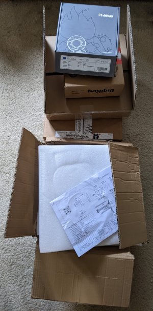
  • The printer parts kit
  • The input shaper, klipper expander board, nevermore filter media, heat set insert tool, PET-GF filament (from Fabreko)
  • The klicky probe kit, replacement fans for what’s apparently cheap, wago connectors, extra magnets, and an extra set of shim rings.
  • The 3D printed printer parts kit.
  • A bunch of misc things that may be useful
boxes.jpg

Print-ahead parts in PETG:​

Print-ahead parts in PET-GF:​

Initial inspection​

  • SrgntBallistic’s build noticed that the Kirigami was over-sized by 0.3-0.5mm. I did the same measurement on my kit and found that it was within tolerance - generally something closer to 0.03-0.05mm.
  • There is exactly one piece of paper documentation included, which is the spec for the steppers. Oh well, I knew that already.
  • There’s no threaded bar, just a printed nut carrier.
 
I'm right at the same stage as you. The V0 parts just came a few days ago and most are still in the box. My plan also is to use the V0 to print a V2. The V2 will be very much customized, the V0 will be mostly stock.

My current printer has zero hope of making usable Voron parts, I tried printing a mini-stealth just to see if the tolerances would be good, but no.

I bought the FormBot printed parts kit. It is complete with all functional and accent parts plus they through it a microswitch of the filament sensor and some aluminum spacers to replace some plastic ones. They use ABS-GL with 10% chopped fiberglass. The parts are more rigid and have a dull matt texture. There are no printer defects other than a tiny corner lift in a place that does not matter. You have to look to see the layer lines

I think the plastic nut inserts are better as they do not add more steel or weight. The steel causes the beams to bow when heated and the mass is just added mass.

I am going to start my own build log and try and cover things others don't.
 
Earth Star Voyager, a Disney tv-series-plot-recycled-into-a-movie-of-the-week from 1988 spent about three hours hinting about “Assembly” that would finally get explained at the two and a half hour mark.
I won’t spoil it for you.
Even if, you know, it looks greviously silly when compared to certain other shows that hadn’t grown the beard yet that also were showing new episodes around then.

Linear Rail prep​

Since it needs to sit in a bath, I figured I’d do all four of the non-preloaded rails before I got started on the actual assembly
I decided to follow the written docs on the LDO website because I hate videos. Basically, 10 minutes in 90% Isopropyl Alcohol in the cute little individualized birdbath to get the grease off. And then SuperLube 21030 is one of the suggested greases.
I printed a pointy tip that goes on the tube, except that turned out to not work very well because in order to get enough pressure to force it as per the LDO instructions, I ended up squeezing it hard enough to make the SuperLube tube burst. So I switched to a disposable dispensing syringe and then that worked better.
(I have a bit of skepticism about the whole “shipping oil” thing, but I’ll do it anyway. For my bike, a lot of people went on and on about how the oil that comes on your chain is “shipping oil” as if the bike chains are sitting on a boat deck getting salt spray on them and a bunch of Actual Bike People With Mechanical Engineering Degrees explained that actually the chains are dipped into hot oil and it’s probably going to last longer if you leave it on. You are invited to try this on your time.)
This has actually been the most annoying part of assembly so far.

Extrusion Prep​

  • There is no un-tapped A extrusion, there’s 10 A/B extrusions
  • There is no un-tapped C extrusion, there’s 4 C/H extrusions
  • I checked manually all of the tapped holes and they seem to be reasonably solid.
  • There is no G or F extrusions (because the Kirigama bed)
  • I am glad that I printed some of the Parametric OpenSCAD tape cutters because they were quite helpful for getting reasonable pieces of blue tape to label the extrusions.

Frame​

  • “Functional parts and decorating parts” doesn’t include the tools directory. Oops. Since I’ve got to print that, I decided to print the neat compliant remix of the idea that I spotted along with the tools folder.
  • There’s a section on “Populating Nut Carriers” that says that I need 50 M2 nuts and M2x6 screws to fully populate the nut bars. The Formbot kit does not use a metal bar, just the printed nut carrier, and seems to have enough nuts. I read forwards in the manual and I think this is the only application for M2 nuts, even if there are more places where M2 screws are required.
  • The assembly jigs came in real handy because I could leave all of the screws finger-tight, get the 38mm piece on one end and the rail centering guides over the linear rail, and then tighten things down. The rail centering guides in the kit seemed to work fine but the compliant version clips in place more easily.
  • I had printed out some No Drop Nuts for LDO-styled extrusions from the VoronUsers repo in PET-GF ahead of time and I thought they fit because if I shoved one into the extrusion, sans nut, it was fine. But once I got started with installing, it turns out that they are printing a bit oversize and tight. I printed some that were better by scaling down the print but then I started printing the No Drop Nuts from the f-zero repo that never made it up into the users repo and those seem to be fitting much better. One of the “charming” properties of PET over PETG is that if you think PETG sticks to the bed hard, PET sticks even harder, which is convenient given how small the contact area with the build plate is, LOL.

Summary: Atmospheric river edition​

I had aspirations of getting farther along on than just the Y rails but the power was out for a few hours and that meant I couldn’t print the No Drop Nuts and kinda disrupted other things as well.
  • Lubing the linear rails is surprisingly annoying.
  • The tools are missing. This sucks. I feel like one of the aspiration of community supported 3D printers is that you can order a set of parts kits and get a fully working printer without having an existing working printer. The tools can be printed with PETG or PLA, which means that you probably know somebody who has a 3D printer that can do it, but it’s still sucky.
 
From a conversation with a friend who I was offering my skills as a 3D printer mechanic to, reminding her that it’s both easy and fun to fix her Ender so she can print things again and she wouldn’t need to feel bad about asking…

Me: “You know, 3D printers are really really neat things! We should strive towards fully-consumer-oriented reliable printers and friendly tooling so that people can alter their world in new and different ways”

Also me: [Looks uncomfortably at all of the mods I have done and want to do to my printers]

Frame - Z Rails​

  • The nut bars feel a little flakey. I can’t necessarily critique the way that Formbot printed them because I pulled them into my slicer and they are really tiny minimal parts and I’m not sure I’d do better on my Ender. As such I opted to assemble them with the nut bar facing towards the linear rails and the nuts facing the extrusion rail, however this means that the M2 nuts want to pop out and get stuck where the screws can’t quite reach. ChrisA, who is building roughly the same printer at roughly the same time points out that the nut inserts are better in many ways than the threaded bar because the steel would make the beams bow when heated and also add weight. I’m assuming that the effect that makes the extrusion backers isn’t going to happen here because the steel is exactly in the wrong place so I’d tend to agree with that logic and would also add that M2 threads are delicate.
  • First error of assembly: On Pg 26, you are adding stoppers to one end of the Z-rails but leaving the other side alone because you add those later. I added stoppers to the wrong side. No biggie, I guess the angle that the image is rendered makes it a bit unclear.

Frame Z-Axis​

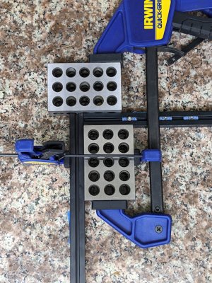
  • My technique for squaring the frame is to use 1-2-3 blocks with little clamps as the right-angles and I used my granite countertop as the flat surface.:
PXL_20240210_232527741.jpg

  • Minor surprise here on pg 35. There are exactly 5 railstops. I had exactly 5 railstops in the kit. I kinda breezed ahead-ish and figured that I was missing either one or three railstops. Oops! Let’s keep going.
  • Okay, now things get weird. My Formbot kit comes with the Kirigami bed so I skip a bunch of pages.

Heat set inserts​

Traditionally I’ve avoided dealing with heat set inserts. Also, I have not used the right tip. So I got the LDO insert kit and put it in my now quite old Hakko that predates the current generation to see if it would work. It seems to.

I put the inserts in the DIN rail mounting brackets for the boards and the DIN rail bracket before I got started on the actual parts because I was a bit concerned about screwing it up.

My one complaint with the LDO insert kit is that I wish they’d included something other than a pair of heat set inserts to set the distance on the tongue, because it’s hard without magnifiers to see where each part ends. On the other hand, getting out my flip-down magnifier hood is always useful for getting things right. And, otherwise, this made the process a lot easier.

Kirigami Bed​

  • Starting out, I am using the Pre-release version of the Kirigami Manual. I am assuming that I’m using the IGUS or a generic clone.
  • The manual’s great but then I run out of the sections that Kag_ee has so then I needed to switch to the LDO guide to finish up.
  • This is a bit of a weird section for documentation across the projects. Most of the kits these days are coming with the Kirigami bed instead of the extrusion bed. There are pros and cons for each bed type but overall the Kirigami bed is going to be a bit happier because of the rigidity for the stock zero even if some of the other projects like the TriZero seem to be happier with the extrusion bed. But the Kirigami bed is a custom-manufacture product and so if you are sourcing it yourself, it’s another barrier between you and a full BOM to start building.
  • The kit doesn’t come with the Stealth bumper at the front. I’m not entirely sure I’ll bother adding one, actually.
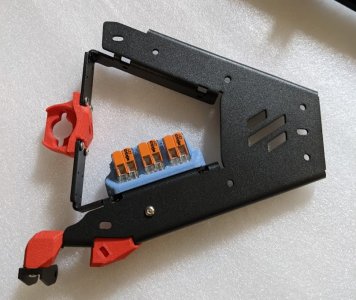
  • Everything came together just fine, so the issues older people’s builds had got fixed. I added the Wago connectors to make wiring easier for me.
PXL_20240211_213605151.jpg

Frame - Z Axis​

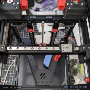
  • Second error of assembly: Everything went together fairly well except that now I need to move the Z-beams a lot from where I had them set up initially. After looking back, I realize I’d set them ~58mm from the outer edge of the H extrusions, not ~58mm from the inner edge of the H extrusions, so I ended up having to do a bunch of re-squaring.
  • Mounting the bed on the Z rails was annoying. It turns out that the best approach was to grip the M2×4 screws with my tiny tweezers, apply threadlock, and then kinda drop them in while wearing my magnifiers. Which is extra-fun because I don’t have depth perception.

Frame - Z Endstop​

  • The microswitch that was provided by Formbot already has the wires ready and also is the type that doesn’t have a lever on it.
  • Minor surprise: The M2×10 self tapping screws are Philips.

Frame​

  • I’m preloading extras. One might even say that I went nuts with the extra nuts.
  • I realized that if I wanted to install the Voron V0.2 deck plate cover for Kirigami mode, it would be awfully convenient to do so right there. The problem that I’m having is that the Z endstop is something where any degree of creeping would be bad and that modification replaces the PET-GF printed Z endstop mount. So I’ll do that mod… later.
  • On pg 58 of the manual, it’s not entirely clear what you are supposed to be using, on the left side of the page. I am presuming that it’s the other end of the IGUS (or generic clone) cable guide.
  • There’s a reminder for the Nevermore filter but the instructions for the ZeroFilter inside of a stock Zero are a bit ambiguous so I just made sure to have plenty of extra preloaded screws there.

Summary: A moment for the mindfulness​

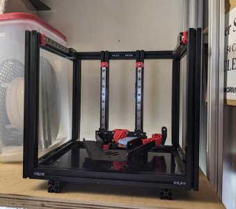
PXL_20240212_033248401.jpg
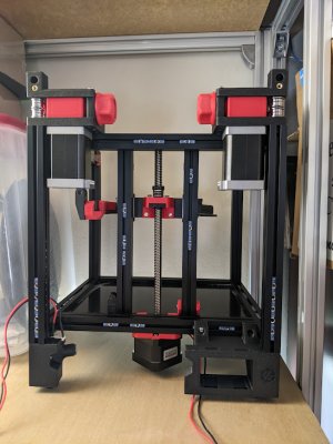
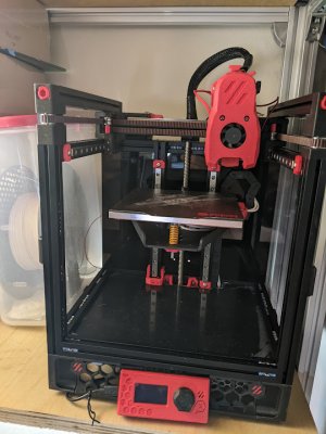
I’d hoped to be at this point maybe a bit earlier but storms and power outages and other projects and other real life things intruded. It’s starting to look like… you know… a 3D printer… instead of a bunch of somewhat random parts on the floor, so I put it up where it’s going to live when it’s done. Which makes me feel better.

I’ve made a few mistakes so far, but nothing too bad. Although I’ll find out later if I forgot to preload something, heh heh.
 
From a conversation with a nice lady who dropped off a giant metal albatross for me to add electronics to that I’ve been working on in parallel with the Voron 0.2:

Me: I have an ungodly amount of different screws organized into little Akro Mills organizers and baggies and things.
Me: But, like, for the Voron 0 I need to get built so I can start retiring my current 3D printer, it’s mostly M3 screws, but it’s 10 different kinds.
Me: And until you’ve accepted McMaster Carr as your personal lord and savior, good luck finding the right screw.
Her: Yes they are amazingggg!
Her: I’m so glad you exposed me to McCarr
Me: There’s a joke to be made there about finding the best screw over the Internet.
Her: Lmao

ZeroFilter test-fitting​

I realized that things were assembled far enough that I could test-fit some things and thus answer some questions about if I had enough nuts inserted in the extrusions. And, at least with the printer as I’ve got it assembled, the Kirigami bed seems to impact the ZeroFilter before it hits the endstop, so I’m concerned about how much room there would be. Coincidentally, most of the shots of the ZeroFilter show the various Zero mods that are so tantalizingly fun looking but I’m not doing yet because I want to build my printer.

Instead, it looks like there’s a side mount that holds the ZeroFilter upright that should give it more room, so that’s what I’ll make sure I have the screws for.

A Drive​

  • Conveniently, the parts for the A and B drive are roughly assembled which means that you do a little less hunting for parts.
  • Other reviews commented on the spacer shim washers being of low quality. I’m using just a plain old pair of calipers but I’m measuring a fairly wide variation in height, plus they don’t look especially well fabricated. Conveniently other folks had mentioned this and so I’d gotten some rings from DFH and they seem to be a lot better such that every one I have is within the tolerance of the calipers to each other. I’m using the supplied washers as washers instead of shim washers where the instructions are just calling for a plain old washer. Coincidentally, while I was building the A/B drive, the same thing came up on the Voron discord as well.
  • I’d gotten some bearings on an auspicious day in my spouse’s faith because I was planning on getting the zero but wasn’t ready to deal with building it so that I’d have the printer “started” on an auspicious day, so I used some in the A drive instead of the supplied bearings.
  • Okay the manual says to use temporary nuts to keep the whole thing from falling apart but doesn’t say when I’m expected to take them off… so I left them on.

B Drive​

  • Second mount went much faster. Maybe I just need to build more Vorons?

A/B Drives​

  • Ah, now I know when the temporary nuts come off of the A and B drive!
  • This is the first time I had to back up a bit. Not because I’d not preloaded a nut but because the preloaded nut I was using was bad and so I had to put a fresh nut in. Not sure if I used one of the kit nuts or if I used one of my existing nuts.

A/B Idlers​

  • On pg 84, it would help to denote which set is the A and B idlers, because I kinda had to extrapolate based on the pictures.

Z Axis​

  • Okay major confusion on the leadscrew nut. The way I’d assembled things using the Kirigami bed means that I already had the leadscrew nut already mounted on the bed, and I was hunting through the pile of printed parts starting to think that I’d lost my marbles and/or a key part.
  • As I’m pre-loading a bunch more screws, I’m realizing it would be nice to have just a map of the extrusions and how many nuts they are supposed to have, in total, and what it’s for. It turns out that BallisticTech has a version of this.
  • Also, I think this section of the manual is confusing, which is made worse by the Kirigami manual. The right thing, I think, to do would have been for the Kirigami manual to have you screw down the leadscrew nut when you are assembling the bed. I don’t like that the manual links to a video that explains how the leadscrew nut works because this feels like part of the actual assembly process… although the sourcing guide still calls the anti-backlash nut the “preferred” option. And then it’s drawing the anti-backlash nut as if the spring is somehow magically not about to spring all over the place.
  • It turns out you need an absurd number of no-drop-nut sleeves. I keep thinking “Oh, this should be enough to hold me for the rest of the build” only to discover that there’s still more to go.

Feet​

  • I thought I was one MR85 bearing short. The extruder takes 2 and the filament sensor takes one more. There’s a canister containing the gear drive kit and there’s two MR85 bearings there. And then the baggie with the pre-wired filament sensor microswitch has a third MR85 bearing, which I didn’t notice. Oh, and then the BOM on the sourcing guide has it wrong. I’m digressing but I would love to see somebody work on the automation and workflow for the documentation and BOM management, understanding that’s an entirely different skillset than things like designing all of the other bits and also, to do it right, might involve doing battle with Fusion360.
  • I’m not entirely sure if I’ve got the ECAS04 collet assembled properly? I’m also going to re-do how filament is fed to make it fit in my space anyways, however.
  • The No Drop Nut is too wide for the screw that holds down the power entry foot, so I left one screw out.
  • I am not installing the color accent pieces. The feet are printed out of ABS-GF and it’s connected with Phillips head self-tapping screws and after I screwed down two of them part way I decided this is a great way to never be able to disassemble the printer feet.

Z Axis - Leadscrew​

  • Looked at how the leadscrew was being mounted and realized that if I wanted to use the Voron V0.2 Electronics DIN Rail Bracket I needed to pre-load some nuts, so I took the feet off real quick and added 5 more nuts to each side.
  • Okay, the whole leadscrew section really is a mess to follow along with. I had put the nut on upside-down, not sure how much that matters of course, so I had to disassemble it. And then to get the screws for the Z stepper in, you end up needing to use a pair of tweezers to drop them in and you definitely need a ball-head key to tighten them. There’s an open issue suggesting that it needs to be done earlier and maybe that’s right?
  • Also, I suspect that there’s some interactions with the No Drop Nuts, probably because it’s holding the nut just a smidgen too far away to engage, so I switched the M3×8 screws with M3×10 screws for those parts.

Summary and future planning​

PXL_20240309_194825318.MP.jpg
A few other things meant that I had a bit of time with the printer sitting on it’s shelf and hadn’t gotten to doing much assembly.

I guess now it’s starting to be clear where a lot of the things go and, looking at the mods I’m planning on applying, where I need to make sure the screws are preloaded, etc. So I spent some time checking the DIN rail mounts, the ZeroFilter, etc.

The Z-axis install is actually the fiddliest part, at least partially because the community moved over to the Kirigami bed as the standard, but also because the manual is itself a bit confusing because it’s trying to accommodate the entire space of possibilities for a leadscrew nut.

And one of the problems with ABS-GF for all of the parts is that a M2 self-tapping screw is not super-excited about ABS-GF, especially the Philips screws that came with the Formbot kit.

I am pretty sure that I am going to end up re-doing the feet and skirt, either by just making my own darn design or because someone’s got one that looks nice and fits my needs. This is a Voron, after all. The primary problem, and one I don’t have a clear ready-made solution for, is that I’m not using the spool holder and I want to be able to swap spools without moving the printer forward on the shelf. I need to see how things are looking as I get closer to done to decide what my best version of filament feed and drybox location is going to be.
 
This work session aligned to the 8th anniversary of Voron’s release

PSU mounting​

I’ve found a few options for mounting the PSU not using VHB tape:

I think I’m going to try the last option. I printed it with PET-GF and test-fit it, which revealed that I had two nuts in the wrong place, so I had to the screws on the Z-axis to get them in the correct place. Thankfully I’d stopped just short of getting the Z-axis aligned, so I wasn’t taking it too far out of whack.

No-Drop nuts and the edge cases​

It’s an understandable problem… but there’s a lot of context required in the Voron community because everybody’s building out their printer, applying customizations, and not everybody’s a documentation writer and it’s a lot easier to distribute STL files and a lot harder to distribute valuable context.

Part of my goal of writing up my build log is to write at at least some of the context, as it is when I built the printer.

Ergo, the story so far on No-Drop nuts:

You probably want to print the No Drop Nuts from the f-zero repo that never made it up into the users repo because they seem to be a lot less fiddly, assuming that you can get them to stick to the build plate. I like PET or PET-GF because it’s extra-sticky!

So far, the cases where No-Drop nuts will interfere:

  1. Four nuts on the front door.
  2. One nut on the back skirt where the power socket screws in.
The second one is a bit of a problem, but since I’m probably going to redo the skirt regardless I’ll leave one screw out. The first one I am catching in time to replace it.

There’s a set of 10mm NoDrop nuts that should be good for the front door. What I did instead, and in a few other cases, was sandwich an extra bare nut between two NoDrop nuts.

Camlocks needed to be carefully un-wedged​

I did an assembly error because the manual doesn’t quite cover what direction the camlocks in the idler mount are supposed to go, so one of them was backwards and that was a bit tricky to convince it to come out.

X Axis​

  • I’ve had a few cases where, because of the angle chosen in the manual, I spent a bunch of time digging through the 3D printed parts box trying to find something, only to realize that it was there the whole time. The XY joints are some of those parts. In a few cases, it would help to show the opposite side of the part, I think. Then again, I am running out of 3D printed parts in the box!
  • The M2x10 self-tapping screws are annoying. I finally found one bit in one driver set that seems happy driving them? It’s a PH-0 from a frighteningly cheap Harbor Freight set.
  • Instead of pre-loading a nut and then screwing the bolt in, I instead decided to just insert the two brackets with the screws and nuts already inserted, which means that I don’t need to think about the No Drop nuts and it also makes the whole thing less annoying.

Summary​

I ran out of weekend before I worked up the energy to actually cut the belts, LOL. It’s a very imposing thing!
PXL_20240317_190723726.jpg
 
I wanted to laser-cut the piece for a lower rear panel with a 8010 MCU fan and my friend-and-fellow-tinkerer CraftySorceress happens to have laser cutter access so she was nice enough to cut it for me.

I told her she’s a cut above the rest.

A/B Belts​

  • I was overly generous with M2x6 BHCS screws for the rails and so I needed to do a bit of disassembly to get a few out of the rail. Oops!
  • Instead of a pre-cut belt, I get 3 meters of belt. Apparently SrgntBallistic’s one easy trick is to run one belt, leave a little excess, and then use that as the length for both. so I did that. I just wrapped a piece of blue tape around the cut mark and that worked well enough. Also, it turns out that, out of the random 3D printed spudger and poking things that I’ve printed, the spudger pencil from orax’s set was most helpful for me to get the belt going.
  • I’m not sure if I made my life harder at some point, but it really feels like the Belt Tension tool should be included as part of the “tools” subdirectory because I am really really really trying not to get my hands and wrists any more screwed up from where they are. Also, apparently the way to go is to use the Gates Carbon Belt tuner - use Motorcycle mode - because it’s presumably doing a little better at the less-guitary more-thumpy tones that a belt is going to produce.

Print bed​

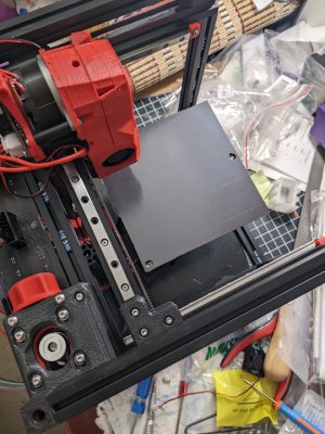
  • I got the Fabreeko edge-to-edge bed heater and magnet plate so I’m using those to build it out instead of the standard bed because folks were complaining about not quite being able to use the full build-plate of a zero on account of the magnets not being strong enough and the heating for the bed being a bit uneven.
  • The Fabreeko magnet plate didn’t come with holes drilled or anything, so I applied it using the instructions on the video the manual links to and then I took a 2mm drill bit, a 3mm drill bit, and a 5mm drill bit from my metric drill set and carefully manually twisted them inside of the drilled holes to get the access holes drilled.
  • The Fabreeko edge-to-edge bed heater comes with the cables all lovingly bundled with a JST connector on the end… but now I’ve gotta cut into the cable bundle because there’s a 150 degree thermostat for safety… but not a thermal fuse.

Summary​

PXL_20240323_175205212.jpg
Reaching the end of the build, it feels like. I need to mount the build plate, build the toolhead, and then it’s “just” electronics. Which is good, because “Why the heck is everybody ordering 100mm and 200mm MakerBeam XLs all of the sudden?” day is coming.
 
As I said last update, it feels like I’m reaching the end of the build?

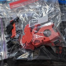
I grabbed the manual and the remaining parts and was able to fairly quickly sort the remaining 3D printed parts into a few small ziploc bags.
PXL_20240323_193356165.MP.jpg

Print bed​

  • In the absence of actual documentation, I’m going to assume that what I’m meant to do is to screw the thermal fuse to the bed with an M3x10 screw and use one of the “shim” washers that aren’t accurate enough for shimming the idlers and pulleys between the screw head and the thermal fuse.
  • There’s kind of a wiring mess here and I’m not entirely sure where the bug lies. You cannot fit a 2 pin JST-XH connector through the cable chain, but both the Fabreeko and stock beds come with a JST-XH connector that’s been helpfully crimped, which means that either you are going to end up leaving a pair of wires dangling, or you have to improvise in one direction or another, either cutting-and-joining or crimping on a fresh connector. I’m not sure what the right “fix” is for this.
  • I carefully sliced apart the Fabreeko cable protector without cutting any of the wires, then I cut the heated bed wires to the right length to hook them up to the Wago 221 terminal blocks that I had printed the Kirigami mount for myself because it didn’t come with the kit. And then I ended up cutting off the JST-XH connector for the bed and I’ll probably just crimp on a fresh connector later.
  • Not as part of the manual but I grabbed the multimeter to make sure that the heater connectors were connected. The Fabreeko wires seem to be roughly 18ga wires when I was stripping them. Also, Wago 221 connectors, the little lever-flip connectors that are popular these days, do not require you to use a ferrule.
  • SrgntBallistic’s wiring diagram comes in handy here as I’m contending with snipping wires and constructing things.
  • SrgntBallistic noticed that the position of the Formbot bed has mechanical interference with the Kirigami bed. I don’t think this has been fixed on the bed I’ve got, even if most of the other problems have been fixed.
  • I am definitely going to have to print the massive nuts mod or the snow knob mod because the stock knobs are way too small.

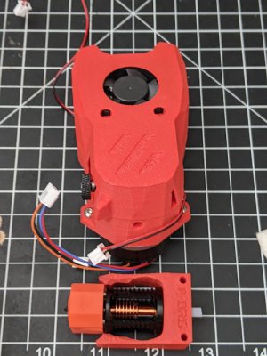
Print head​

  • I am not sure what lube is suitable for the MR85 bearings in the extruder so I’m just going to put in the same SuperLube that I used on the rails.
  • When it comes to glues, I guess you could say that I’m not really much of an adherent. I generally design things to not need glues, especially superglue. Naturally this means that the superglue that had been sitting around that was described as not being like the other superglues is all dried out, before I’d ever gotten around to opening it up and trying it out, which meant I needed to get a fresh tube real quick. Would Epoxy have worked? No idea.
  • I did have to sand a bit off of the metal gear shaft in order to get things to fit properly.
  • When I was screwing around in Step 5 trying to figure out what I was supposed to do about the M85 bearing, I opened the container with the drive gears, which required me to peel off the tape holding it shut. Naturally, in between then and now, it managed to pop open and spew it’s contents and so I had to do some very careful digging to find a few bits. The magnets for the door were true bros in this case because that’s where the M85 and grub screw were but the little plastic washer thing was not magnetic and required a bit of a search.
  • I realized that I only got one 3010 24v blower fan and I should have gotten a second one. So I ended up using a genuine gdstime fan for the hot-end cooling fan and used the stock blowers. My impression is that I’m going to want to upgrade to the DragonBurner relatively quickly and that one uses 4010 blowers.
  • Manual writing is hard. For example, there’s a part where the manual talks about why you need a M3x10 screw so that it’ll have extra thread on the back side and two screw holes are slotted so you can adjust the backlash. In order to do this right, you’ll probably need to understand a bit of the why, even if the rest of the why is what makes a mechanical engineering education.
  • I ordered my kit with a Phaetus Dragon ST hot-end because I really really like one-handed nozzle tightening. And when I started trying to assemble it, I realized that the Dragon ST that I was looking at had the kinda unfortunate E3D V6 style mount that I think even Sanjay felt bad about in retrospect and was about to flip out because the provided hotend mount was not designed for the V6 style mount… and then I realized that I could just unscrew the V6 mount adapter and everything was fine.
  • BOM and/or sourcing issue: The BOM calls for M2.5x12 screws to mount a Dragon and there are none provided. I used some M2.5x12 screws I already had, except that the screws were too long. So I switched to the M2.5x8 screws provided and those fit perfectly. The error is either that the Dragon’s mounting screw depth changed, the screws were wrong all along, or the depth of the screw holes changed. Unclear.
  • SrgntBallistic got a 104NT-4-R025H42G thermistor for his hot-end but mine came with a generic 3950. I’ve got an extra higher-temperature handy, thankfully, so I’ll use that instead.
  • There were some folks who found that their umbilical breakout boards were mis-wired with the molex connector in the wrong orientation. Mine seems to be fine. One thing to note is that the polarity of the fans is labeled… however the input fan connector has the opposite orientation to the output fan connector.
  • The manual doesn’t state but it’s generally understood that you want to use the 2mm inner diameter teflon tube for the hot-end’s teflon tube.

Getting started on the software side of the fence​

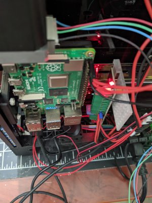
I have various issues with Raspberry Pi the company. The Raspberry Pi started out with this vague goal to re-create the experience of the BBC Micro in the UK, but over time they split it into the foundation and the company… and so there’s no hero companies with capitalism… but there's been a few incidents where they've been tone-deaf and not supporting their stated goals.

Also, they’ve had some catastrophically silly design flaws with the USB spec.

On the other hand, you want a Pi-shaped object to run klipper on and interface with the printer’s microcontroller side and the easiest option seems to be a genuine Pi because I trust the Pi OS’s longevity over the rest of the similarly-sized objects, so I’m not going to use that instead of the included Pi-shaped device because it makes my life easier if it’s identical to my other devices.

Likewise, it comes with a Sandisk branded MicroSD card. I don’t, in general, trust Sandisk cards right now after a very fancy and very genuine Sandisk card for my camera started acting up. Thus, I got a Samsung high endurance MicroSD card instead.

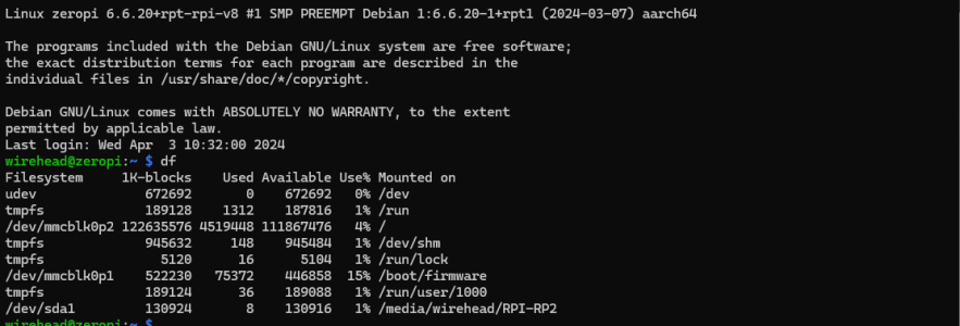
So, the first step is to download the Raspberry Pi Imager, tell it I’ve got a Pi 4, pick the 64 bit Raspberry Pi OS, and then when it asks me if I want to add some settings, I filled in my Wifi SSID, set my account name and password, and turned on SSH, at which point I can make Ansible do the rest of the work.
 

Summary​

PXL_20240406_173621781.jpg
I’m assuming that the MiniSB is probably one of the trickier bits of assembly with all of the interlocking parts. There’s a lot of stuff where, had I built a blanket fort around a not-well-calibrated printer, I could probably print some ABS parts and they’d probably have some elephant’s foot and roughness and whatnot but they’d mostly fit together, maybe with some sanding and forcing.

The MiniSB is a different matter entirely. All of the work on putting in heat-set inserts into relatively simple parts paid off because now you have some fairly dicey inserts to insert. And a bunch of stuff needs to fit together fairly perfectly, etc.

On the other hand, I’m not sure about how well the MiniSB is going to work out for me long-term. Okay, so it looks cute. And if you look at the cost of a Bondtech gear kit or a cheap clone gear kit, you can kinda feel like it’s still good for self-sourcing to go back to the least expensive parts and not require a person to purchase a fancier extruder. And so on. There’s a bunch of design concerns that may not apply to me.

Mostly I’m annoyed because, compared to the Bondtech DDX on my Ender 3v2, the DDX has the main gear positioned such that I can jog it back and forth to load and unload filament manually. And the tension knob seems to be kinda dicey, although I’m not sure what would happen if I were to replace it with a genuine Bondtech knob since I don’t think I have a genuine set of gears. But it’s fine… this is a Voron.

I’m reaching the end of the build, I guess. Which is good, because my Ender 3v2’s acting up and I know what to do, I’ve even got the parts. On the other hand, if I’m going to spend a bunch of time hunched over a 3D printer, I’d rather it be the new one, not the old one. We’ll see how this goes…
 
One of my friends was visiting a while ago and we were doing the “parallel play” thing where we were both working on different stuff the same time. And then she realized that she needed some springs, so we walked to the local Ace Hardware, which I’d never actually been in, so we had to also browse the place.

I put one foot in the glue aisle and she looks at me and says “We are no longer friends”

(She’s kidding of course. She just really hates most adhesive products because a glued thing came apart during judging and so she’s gotten really good at designing things that can be bolted or screwed or snapped or whatevered together such that you can maintain them later, which is great because we’re also both extremely mad at this person who blandly suggests that it’s OK to hot-glue a Li-Ion battery down in a cosplay)

Anyway, the thing that finally came to fruition was my particular answer to the “How do I assemble my Zero without all that VHB tape” problem.

Print head​

  • The instructions aren’t clear so I’m doing things the way I did the Mosquito I put on my Ender 3v2: Apply a liiiiitle tiny bit of Boron Nitride thermal paste to the thermistor and heating cartridge, shove them in, either let them dry overnight or warm them up at 90°C for ten minutes. I ended up deciding it was easier to wire up if I put the wires for the heater sticking out the opposite side as the thermistor and dumb-lucked the sides.
  • I do not see any instructions for what kind of screw to use for the umbillical PCB. I ended up using a M3x8 thread-forming screw. The folks on the Voron discord suggested that it was probably OK to just use a M3x6 screw and thread it in to the plastic.

Electronics and wiring​

  • Okay here’s where I slipstream the Voron V0.2 Electronics DIN Rail Bracket into my build. I had printed some alternate brackets but I didn’t end up using those. The DIN bracket for the SKR Pico is just slightly wrong, it’s got one hole out of place but it’s functional as-is probably.
  • I did have to switch the input voltage.
  • Again, I’m also slipstreaming the screw-on bracket instead of using VHB tape. It does fit my Zero. I printed it with PET-GF on my Ender 3v2 on a G10 bed with Elmers purple gluestick to make it not warp. I used the 4.6mm hole version, and I guess the big thing not explained is that the M3x6mm screws (I ended up using M3x8mm screws because the NoDrop nuts sometimes don’t quite grab with the 6mm length) are used to screw down the four mounting holes, plus one of them goes into the threaded insert via the tap on the side of the PSU. The M3x10mm screws go in through the side. And you really want to mount the power supply to the bracket before you mount the bracket to the printer.
  • Out of a spirit of paranoia, I decided to order the BOM-spec AC power inlet from DigiKey and the matching fuse instead of using the one that came in the box. Not a diss on Formbot, just my own fastidiousness and paranoia.
  • Also out of a spirit of paranoia, after I’d hooked up the wires as per the diagram (The wires are in the IEC scheme) I checked with my multimeter to make sure that things were actually connected right with the continuity probe. And then I plugged things in with just the power supply connected so I could make sure it’s actually putting out 24v and the polarity is as I expect it to be. And then I plugged in just the SKR Pico to verify that the 5v out wires were actually putting out 5v and the polarity was as I expected.
  • Either the stepper motor thermal compound on the SKR Pico isn’t very sticky or it’s some kind of removable putty? I dono, this doesn’t make me feel very good at all.
  • I figure the best thing to do, at this point, is to get the current Klipper version and image installed now that I’ve got enough of it such that I can ssh in. So I set the jumpers for flashing mode, booted the pi… and now I have to actually provision the pi.

A brief word on my intended infrastructure​

Understand that I’ve spent a lot of time doing various infrastructure work, both “in the cloud” but also on the real hardware. So… this is not going to be a normal Klipper setup process, because I’ve got opinions and I’m not afraid to whip out the chainsaw and cut things apart until it works the way I want it to work.

I’ve got an Intel NUC that’s set up with a mirrored array of real drives and that’s my home Linux box. If I’m talking to hardware with a Dockerized Linux-oriented build process like ESPHome, it’s a zillion times easier to plug the device into that than try to get USB connectivity routed through a hypervisor on my main computer.

Because Pi’s, up to the recent 5, are using SD or MicroSD cards for storage where they aren’t super trustworthy in terms of long-term longevity, I generally want to avoid having too much that’s running there that I can’t replace easily.

So, overall, I want things to be reproducable. Also, I don’t want my home DevOps infrastructure to get in the way of having fun.

Ansible is in a nice sweet-spot. Unlike everything that came before it (Chef, Puppet, et al) it doesn’t rely on an agent and control server, it just uses SSH to log in and do things, offering a vaguely reasonable but not especially pure intermediary between a stateless declaritive configuration language and the stateful operations required to actually apply changes to a running machine.

Docker is also in a pretty darn nice sweet-spot. There were docker-like things before Docker came out, such as lxc, but Docker provided a really amazing abstraction layer that, for better or worse, was real easy for folks to get started on.

Thus, my goal is to put the minimum amount of functionality, using Ansible to set up the box and then Docker to land the images, on the Pi, and then run as much of the higher-level tooling on my NUC.

Summary​

step9.png
This feels like a worthy accomplishment for “Why the heck is everybody ordering 100mm and 200mm MakerBeam XLs all of the sudden?” day
 

Ansible provisioning​

I don’t have the energy to turn this into a proper Ansible tutorial that’s generic enough to be safely shared so I’ll be brief here.

Basically, when I set up the firmware image, I gave it my username and ssh key so that I’d be able to just run Ansible.

And then I’ve got a set of standard roles already set up that do things like give me a proper home directory with the right files, docker, etc.

Part of the nice thing about a tool such as Ansible there’s a community role that wraps up very nicely the care-and-feeding for getting Docker going. And if something zaps the file structure of my Pi’s SDcard, I can just start fresh and everything will be back where I set it up, more or less.

In order for this to work, when I’m tweaking the configs, I need to make the changes via Ansible and apply them instead of making the changes locally.

Klipper firmware build​

prind is fairly close to what I want and is going to save me a lot of effort.

Except I don’t really need the Docker Compose part. And, actually, the idea of aliasing make weirds me out in general.

So here’s my shell script, which mirrors what the prind docker compose file is doing:

Code:
#!/bin/bash
VERSION=v0.12.0-143-g01c7befa

docker run --entrypoint make --rm \
-w /opt/klipper \
-v ./config/build.config:/opt/klipper/.config \
-v ./out:/opt/klipper/out \
-it mkuf/klipper:$VERSION-tools $@
And the process to build an image looks like this:

Code:
mkdir config
touch config/build.config # to force the creation of a file to map instead of a directory
./build-image.sh menuconfig # replace make with the name of the script
./build-image.sh
I kinda left this ugly and just manually moved the built klipper binary over to copy it.

Electronics and wiring​

  • Ended up putting on a new JST-XH connector on the bed thermistor wires I’d cut on Step 8.

Skirts & Panels​

  • The way the order of setup is going, it is way too easy to end up dropping a screw into the power supply while putting the skirts on. I’d go so far as to call this a design flaw in ways that all of the other side-effects of a smol babby printer are not because this is something that could start a fire.
  • The straing relief and umbillical support is just a smidgen too small.
  • I think the most annoyingly badly documented part so far is the umbillical. It’s 100% guesswork, which is fine for me but might present a lot of problems for a new user.

My BTT SKR Pico sucks​

I was just checking through all of the wiring because it’s actually at a point where I could power it up and start getting it printing PETG without the full chassis on. So I went through and checked all of the wires to see if everything seemed secure.

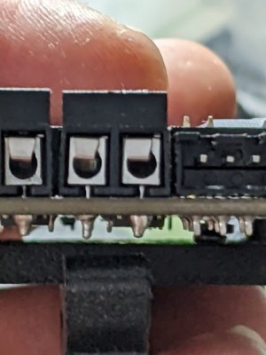
One of the screw terminals is bad. The one for the hotend, ironically, which is also the one that went bad on my Ender 3v2.

PXL_20240407_225057507.MP.jpg

The screw terminals are the sort where there’s not a good-side/bad-side thing, you can just jam in a wire and it’ll end up on the right side. You can see how the other ones have a metal contact that bends down to hold the wire in place and make the circuit. And the one on the farthest right… no matter what I do with the screwdriver, the contact never moves.

The thing that concerns me about my particular Pico is that all of the screw terminals feel flimsy as I tighten them where the Creality board for my Ender 3v2 also has cost-optimized screw terminals but those aren’t nearly as bad. These are, and understand that I default to using screw terminals for my electronics designs, probably the worst screw terminals I’ve ever seen.

Also, as I said last time, the heat sink is held on by what feels like putty.

The LDO kit… which is what folks tell you to get because you’ll end up swapping out all of the parts from your non-LDO kit till you get to the LDO version… has a SKR Pico. So I’d like to think that if all of the SKR Pico boards were this bad, there’d be a lot more unhappy people.

Other than sending in a support ticket, do I?

  1. Buy another SKR Pico so I’m not sitting around staring at a broken printer for however long formbot and/or BTT take to figure things out because it can’t hurt to have a spare, hoping that I’ll get lucky on a $39 control board?
  2. Buy a different board that’s fairly compact because maybe BTT is making the SKR Pico too cheap. Say the SKRat control board?
  3. Get out the soldering iron and fix it myself because I can and because there isn’t a better replacement anyway? Maybe put a Phoenix-style connector this time?
 
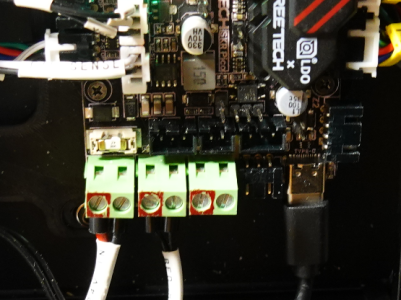
Yes, these terminal blocks are garbage. One wasn't even threaded (the hotend one) ! Replaced them all with beefier ones I had in stock, made of plain metal instead of this skinny sheetmetal.
Requires a lot of heat, even with the desoldering station, because of the copper planes all around the pads. But definitely doable and worth the effort.

Poor quality, and poor design ; they didn't even take advantage of the dovetails because of the silly grid placement. The guy that routed the PCB most likely does not know how terminal blocks are supposed to be assembled.

1712965415173.png
 
Yes, these terminal blocks are garbage. One wasn't even threaded (the hotend one) ! Replaced them all with beefier ones I had in stock, made of plain metal instead of this skinny sheetmetal.
Requires a lot of heat, even with the desoldering station, because of the copper planes all around the pads. But definitely doable and worth the effort.

Poor quality, and poor design ; they didn't even take advantage of the dovetails because of the silly grid placement. The guy that routed the PCB most likely does not know how terminal blocks are supposed to be assembled.
Yeah, I'll probably do the same, assuming my soldering iron has enough heat output for the job. I'm assuming that they designed it in the biggest hurry during the time period where you could not get STM32's but could get RP2040's. I guess yay for them actually using a fill underneath the screw terminals?
 
Just thinking of something... Could be on purpose : 6-pin screw terminals cost more than 3x 2-pin, and it's unlikely pick and place machines could assemble the three components in one...
If you don't already know this YT channel, have a look to Mr SolderFix. Tons of tips and tricks.
Another way to remove the terminals is to destroy them, and remove the remains one by one. But it is risky.
I dono, I've tended to order 6-8 contact screw terminals and split them on the dovetail to get down to 2-pin versions because at least when you are getting them from DigiKey in the US it's usually somewhat cheaper... except for one connector type where the 8 contact screw terminal was actually an indivisible 8 contact screw terminal, LOL. Not sure what the impact on assembly is either.

I guess it makes it less likely that you'd line up the wires wrong, tho.

Hm, and actually, no I haven't seen Mr SolderFix...
 
Okay, so we started last weekend with zero working printers and ended up with zero working printers. Let’s see how this weekend goes…

The SKR Pico and Formbot support​

Yaaj on the Vorom forums had the same problem. I’m unclear on if it’s “Hey, we really need to get a small Ender-sized board out that doesn’t use a STM32 because we exhausted out favors out of our suppliers and the RP2040 is still available” or it’s there to make it a bit easier to not screw up the wiring.

Hard to say, in spite of having very strong opinions on a bunch of things, I’m absolutely not a trained electrical engineer. I will be trying my hands at rework for this SKR Pico when I have a replacement at hand.

Either way, I’m not sure if I were to get angry and replace it with … say the SKRat … I’d have a second crappy board because everybody just tolerates bad BTT boards or if it’s just that I need to get a board from someone else.

It took a bit of back-and-forth but I was able to convince Formbot to send me a new SKR Pico, but it’s on the way.

The Klipper Expander I already have…​

It hit on Wednesday that I have a complete and reasonable solution to my problem already.

I got myself a Klipper Expander because it seemed to be useful. And it’s able to handle 3A per MOSFET, which means that 24V × 3A = 72W, which is more than the hotend is capable of. Which I was in the middle of something else so I didn’t remember how ampere the capacity of the MOSFETs were so I realized that, worst case scenerio, I can breadboard a Klipper-Expander-like-thing solely using parts sitting around my geekroom.

While the RP2040 devices can just mount as a filesystem, STM32’s use DFU, so I had to re-arrange my dockerized provisioning scripts. I’m not sure what the final version thereof is, but this works well enough for now. Because each board has a unique klipper.config file to drive the build, I now have a build-image-skr-pico.sh script that loads the config for the SKR Pico and a /home/wirehead/klipper/build-image-expander.sh script that loads the config for the Expander, plus a /home/wirehead/klipper/dfu-utils.sh script that runs dfu-utils inside of the docker container.

Once I got that moved over, I was able to follow the Klipper Expander flashing guide to flash the firmware.

Bonus points: I have a DIN rail mount that I’ve already printed that can be pressed into service as a temporary bracket.
PXL_20240414_160021162.MP.jpg

A digression on Klipper and commercial printers​

I would suggest that a lot of things in the open-source and reprap-derived world of 3D printing may tangentially or otherwise make some people some amounts of money, but one thing I do push back hard on these days is the idea that an open source developer must necessarily act such that other people can make money on their hard work.

Klipper and the way that it has been structured make this a bit convenient at the cost that commercial klipper products will cause you to eventually waking up, realizing that your 3D printer has filled your house with autonomous killbots.

Klipper requires a reasonable chunk of a real operating system. This makes all of the higher-level Klipper tasks real easy because you can just write yourself some Python instead of screwing around with Arduino firmware.

However, it’s basically impossible to package a complete operating system plus Klipper in such a way that it doesn’t necessarily phone home and that it won’t eventually get hacked in a distributed fashion such that a bunch of people wake up to house-fires and/or a geekroom full of autonomous killbots. It’s sadly part of the nature of the beast and why IoT devices, as a general class of devices, kind of suck. This looks a lot worse when you realize that doing this right requires that you need have a company with a well-developed site reliability and software infrastructure team, including people who know security very well… and then they also have to get good at all of the mechanical and sourcing and everything else… and then they have to deliver the printer at an astonishingly cheap price. Bambu’s misstep where they triggered phantom print jobs in the middle of the night is one example of the difficulty here.

Vorons and other open source printers don’t solve this problem, but at least it’s now my problem to patch my own darn Linux devices, which I can do using whatever patching mechanism is appropriate for the environment within which I exist.

Mainsail + Moonraker + Klipper​

What wasn’t initially obvious to me is that Mainsail and Fluidd don’t have a server-side component to them. But, yeah, any storage is done in the browser or on the local machine.

Which makes things make a lot of sense. Of course neither Mainsail or Fluidd would have plugins because everything’s in the browser!

So I ended up setting up Mainsail on my NUC using an Ansible-ized version of the instructions, making a simple Ansible role named klipper-control to represent the control plane, and then I used a config file that looks something like this:

{
"defaultLocale": "en",
"defaultTheme": "dark",
"hostname": null,
"port": null,
"instancesDB": "json",
"instances": [
{ "hostname": "xxx.xxx.xxx.xxx", "port": 7125 }
],
"remoteMode":true
}
Klipper and Moonraker took a bit more effort. I’ve been adding everything to a klipper role that represents everything that needs to actually run on the Pi. I’m using the prind containers but only the containers, because I replicated what it was trying to do in docker-compose with Ansible.

Prind’s containers are hardcoded to run the process with a UID of 1000 which forced me to do probably the right thing, which was to create a klipper user to sit at that UID.

And then also, because Mainsail is a single-page-app with no functionality inside of the browser, you need to use the include functionality to insert a mainsail.cfg provided by Mainsail into the klipper.cfg file. This feels awkward in terms of long-term print-farm maintenance to me.

The advantage to the way this is working is that when I build a second Klipper printer, all of the pi-side work is completely done; it’ll go much faster than the non-containerized build processes.

Machine bringup​

  • I flashed the display using the V0 Display flashing guide to make sure everything was current.
  • I checked to make sure I’ve got the same motors and thusly used the pre-calculated values from SrgntBallistic’s config to get started.
  • I started going through the general Initial Startup guide first.
  • I went through testing the fans and stuff and discovered that the Triangle Labs 3D sensor I put in place of the stock 3950 sensor has some bad wires, so it’s back to the stock sensor. Also, I realized that the hot-end fan wasn’t turning because the wires are reversed, so it’s back to the stock fan as well, ugh.
  • Then I had to check out the sensorless homing guide to try and get that calibrated. It’s really confusing when you are calibrating because every time you run a G28 X0 or G28 Y0 command, it will lower the Z axis slightly… which is arguably probably a safe operation, but this also caused some confusion. But I have a printer that’s properly homing. I ended up, while going through the process of setting up homing, using the M18 code to turn off all of the stepper motors and manually re-setting the positions.

Summary​

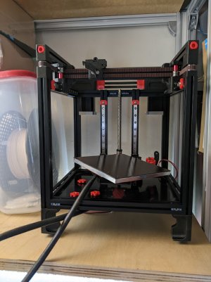
Everything seems to be working?
PXL_20240414_160030585.MP.jpg
 

Prelude to first print…​

  • I washed the Formbot-provided flexplate with dish soap because I figure if I’m going to screw up a flexplate, it’s the right one to screw up. As I’m washing the smooth side, I feel something coming off. Okay, that’s not good. But, no, oops, it looks like that was a protective coating to keep the smooth side smooth.
  • I set the Z-endstop position with an eye towards seeing where exactly the Kirigami bed interfered with the screw for the thermal fuse and it’s definitely eating up a few mm of travel.
  • Overall.. the bed-leveling process seems better with Klipper and the BED_SCREWS_ADJUST macro. What I’m really interested is in how much the bed drifts over time, of course.
  • Did the PID tune for both the hot-end and the bed. One thing I’m thinking about is having the klipper.cfg be a skeleton file so that Ansible could put it in place and not need to touch the config settings saved, because right now, Ansible will overwrite the saved settings for virtual endstops, PID tuning, and Z-endstop position.
  • Did the extruder tuning, the default is pretty close to fully right, just a little bit off.

First print​

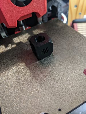
I decided, before getting too far into things, that I’d at least print a proper Voron calibration cube. So I’m using the SuperSlicer provided profile with everything left to the defaults. And since most of what I’ve got is PETG I figured I’d just print everything with that, for better or worse?
PXL_20240414_195744258.jpg
Seems actually pretty good considering that I need to actually properly calibrate things, LOL.

Spoolman​

🎶Well, all my friends are ABS

(All my friends are black and red)

Spoolman

And all my friends are S.R.E’s

(They beat the software with their hands)

Spoolman

Oh, hmm

Spoolman, come together with your hands

Save me, I’m together with your plan🎶

(With apologies to Soundgarden)

This is something I’m super-cheerful about being able to run on my NUC instead of on the Pi. With OctoPrint, you’ve got a bunch of functionality that ends up existing in plugins, filament spool management being one of them. If you have multiple printers, you probably want to have a single database with all of the spools shared between the printers, which doesn’t fit into that model. Thus, in this case, Spoolman.

For me, it’s just another container running inside of the klipper-control role on Ansible and a tweak to the Moonraker config file to point the printer at spoolman.

Starting the wrap-up process…​

I’m (mostly) back to having a functioning 3D printer again. Looking at it move, it feels like it’s already printing faster than the Ender 3v2 and presumably once I’ve got it fully tuned, it’ll potentially be faster still.

The first pre-printed part to break was one of the DIN rail electronics mounts. It was probably a silly idea to print that in ABS-GF in the first place, of course. I’m not sure what the best way to destructively inspect the printing so as to make a better guess as to how fast I should have a full set of replacement parts ready.

The heatsink won’t stay on the SKR Pico, which is putting an end to printer commissioning. I’d intended to work my way through the Ellis’ Print Tuning Guide as well as rigging up the accelerometer to test all that out but that seems like a bad idea if I’m worried about frying the SKR Pico’s steppers. If I had been thinking more clearly I’d probably have ordered thermal glue earlier in the week, so we’re still in the land of a 3D printer that’s not fully functional.

Just ironic that the thing that has made this build the hardest is the controller board that’s hard to avoid because it’s also on the current rev of the LDO kit.

It would have been really nice to put an arrow or some sort of marking on the corner pieces because every corner is slightly different and only a few of them are actually the obvious sort of difference so I gave up and just used the middle mounts such that two of the sides are enclosed. This feels like progress because my Ender 3v2 was never enclosed.

So the big remaining items at this point before we’re in full extra-credit land are:

  1. A fully operational SKR Pico, ugh
  2. A full Ellis tune
  3. Cable management
  4. All of the panels installed so it’s all able to be closed up
  5. ZeroFilter
  6. Serial number
PXL_20240415_003637563.jpg
 
Top