What's new
VORON Design

Register a free account today to become a member! Once signed in, you'll be able to participate on this site by adding your own topics and posts, as well as connect with other members!

Voron 2.4 r2 350 Formbot Kit with stealthburner, revo and tap

Upperbottom

Active member
I'm about to start building a Voron 2.4 with a Formbot Kit as base (yea NOW I know it's a lottery...but at least the cables come pre-cut and crimped), then add Tap. Stealtburner is now standard in the FB-Kit..

What could possibly go wrong 🤪

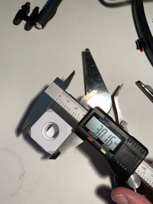
Currently only the Tap-kit and the Formbot parts have arrived. Eventually I will get my printed parts but while waiting I greased the rails (veeery satisfying work and nice woshwoshwosh), I checked the BOM and I'm currently prepraing myself for an inhumane amount of heatset inserts.

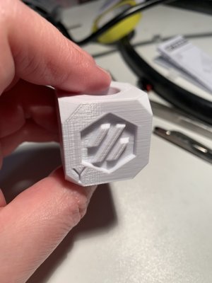
The picture shows my current printer (ReprapPro Mendel Tricolour) printing it's first VoronLogo in the heatset-trainers.. Unsuspecting of it's future in my parts-and-projects drawer...
"You served me well, now it's time to rest"*

IMG_0318 2.jpg

Next up: convincing my better half to yield the kitchen counter for a day to get a great square frame...

*ok.. this sounds much more affectionate than it should be... NO automatisation whatsoever, the cooling is abysmal, speed would probably be better to use a 3d Pen, ringing more than an ancient schoolbell and the killer is a tempramental Z-axis that punishes any sudden and fast moves by seizing up and drooping one side... However: it was my printer, it could in theory print 3 colors and i learned a lot building and maintaining it**
**yes.. I know.. I could probably adress a lot of these issues with tuning, adding better cooling fans, better bed, better Z-axis bearings and screws and maybe a bed probe and new firmware.. maybe klipper? But then again.. why not a new one. Just because you can still drive a t-ford why not build something more modern...
 
Ok.. first build day.

Managed to free the only flat surface of the kitchen and get a nice and square frame.

BriskRewardingDove-max-1mb.gif

On the "to-threadlock-or-not-to-threadlock-thy-frame" question, i went heretic and used threadlock (btw. "blue" fischer-threadlock with a nice pump dispenser)

The square showed nice 90 degree angles, and the diagnoals were also within tolerances.

IMG_0330.jpg

IMG_0331.jpg
Next were the rails and the bottom panel and DIN-rail.
Fortunately my old printer was able to produce the rail-guides. I used a m3 screw to get the 3mm space on the bottom.
To help me get the spacing for the t-nuts correctly i put the rail on the extrusion and marked the relevant holes with a pencil, the markings can easily be removed with a soft eraser.
Since there are an even number of holes in the rail, I had to decide where I left out a nut and decided to leave one space on the bottom, but put a screw in the top and bottom hole. My resasoning being that the upper part of the frame "shakes" more*

Finally i installed the floor plate. Again, rughly marking the t-nut-hole with pencil, inserting the nuts, and then tightening everything with the screws. Nice and clean. I won the hole-lottery!

IMG_0332.jpg
Aaaand.. thats all I can do for now without printed parts.
They are in limbo but I hope to get them soon...


*nononono! MY frame is RIGID! NOTHING shakes!... eVVAAAA!
 
My parts finally arrived!
Now I can reveal the name of my machine "It was Grey!" (Futurama nerds will know...). The colorscheme is grey-blue, the parts were sourced from Brink-3D and so far the quality is quite nice.
The surface of the bottom panel was quite nice and shiny, so i put down a layer of masking tape.. just have to remember to remove it later... :unsure:

I managed to put the z-drive assembly together, and had slight problems with the 5x60 shaft, where the tolerances between the 20T pulley and some bearings were quite tight.

At one point there might have been some choice-words, sandpaper, a small hammer and a vice ivolved, but in the end everything fit together and spins freely. A win i my book!

IMG_0340.jpg
Next the "Eye"dlers... now the whole build is followed by some angry silvery eyes... Not quite sure how to feel about this...
IMG_0341.jpg

Up next.. bed and x/y gantry...
 
The next few steps were a little more challenging, but nothing that was beyond manageable.
I started by NOT following the manual, and postponing the bed installation to a point later when the risk of dropping anything on the bed are lower...

So I went directly to the x/y gantry.

A slight setback was when a printed part failed, but nothing that could not be fixed with a droplet of superglue. I'll have to watch the part and will make it one of my first spareparts to print..

The next mistake was mine.. mine alone..
IMG_0356.jpg

Yea.. about right and left.. not my strong side.. the front idlers were switched, no biggie..

But.. fixing it gave me a chance to "pre-un-rack" the gantry before installing so when I put it in the frame it was really smoth going front to back..
IMG_0357.jpg

After re-watching the un-racking video to make sure i hadn't missed anything I had to go to the TAP-manual to prepare the toolhead for the x/y belts.
The kit from Meltbro is complete and the sensor-board was already fitted with the propper resistor to prevent magic-smoke release. Unfortunately the tap-parts are not in the color of the other printed parts, but that's no biggie, black-goes well with the the frame.

While the formbot rails were somewhat clean and easy to clean and regrease the smal rail of the TAP-kit was an oily nasty mess.. and it was slightly "crunchy".

I took it apart and cleaned it best I could with isopropanol. Applying grease was easy because the sled was already off the rail and the bearingballs were accessible. The rail is still a little crunchy, but should hold up. At least I know of this possible point of failure.

The rest of the tap-kit were no problem, to assemble, but first the x/y-belts have to be fitted...

To be continued....
 
Just a quick update, belts are fitted, clockwork 2 assembled, but I can't continue because i misplaced my hotend-holder for the Stealthburner hotend.

Jupp.. I'm an idiot!

So now my old printer has to produce Voron-spec ABS parts... Pictures coming soon..
 

Printing detour....

The challenge: Print ABS on an open bedslinger that struggles to print PLA models at quality.
So.. for the first time in it's 10 year lifetime it has to go over 210 degrees on the hotend and to 100 degrees bed temperature.

I couldn't find a good enclosure (makeshift or otherwise) so I opted to print with a draft-shield.

A benchy should give me hints towards possible tweaks...

The result:
On the theme of me being an idiot: print a draft-shield with one line width and expect it to stay put...

IMG_0370.jpg

BUT.. under the mess is a decent first try Benchy wich gives me enough info to adjust settings try real Voron parts....

Oh.. and if you have a custom end gcode make sure your 5mm nozzle travel in z direction is RELATIVE not absoulte... This is the reason I have an emergency switch on my old printer...
(wasn't fast enough though.. )

IMG_0372.jpg
A lot of the surface imperfections are due to the "Lassoing" of the draft-shield extrusion. The z-axis is a mess... but OK for a m5 threaded rod, fastened with a rubber hose to the motors and held in place by straight rods with an iglus bushing (bearings? PAH! to expensive, this is reprap, WE PRINT our bearings...)

In good news: Dimensions are OK, layer adhesion OK, bridging OK.
First layer maybe little less squish, not enough cooling, but I won't adjust the latter, to prevent curling and delamination.

Finally the real parts.
IMG_0376.jpg
Yea... somehow the old gcode was still active, so I got a nice burn/meltmark in the only functional part of the front part of the mount (this time i was a little quicker...).
So nothing a file, an exacto knife and a drillbit wouldn't be able to fix...
The other part was fine... except for the overhangs and bridges... Cooling is a bi**h!
IMG_0378.jpg
Ohterwise, not bad for a heap of hardwarestore rods and nuts... Then again.. Adrian Bowyer was part of the design team.

Build contiued​

Next part was completing TAP and attaching the toolhead.
IMG_0379.jpg
...and clockwork2

IMG_0380.jpg
Before proceeding with the electrics/electronics I tested TAP and the SB neopixels, as well as continuity/resistance of the temperature probe, heater and fans.

IMG_0382.jpg
(I will talk about the quality of components in the summary)

All was well... appart from the bed, the mechanics were complete!
IMG_0383.jpg
Not quite ready for cereal, but I guess a nice medicinal Whisky is in order...
 
Baby steps..
Today I mounted the printbed.
First fitting the magnetic sticker, to get the holes right i put the plate on the sticker, marked the screw positions and punched the holes with a belt-punch.
IMG_0384.jpg
The largest hole was still too small, so i reamed the holes with some drillbits with satisfactory results.

Next step: mounting the plate on the thumbnuts and the correct place on top of the T-nuts.

Again I marked the position of the screwholes on the extrusion, moved the t-nuts in position and put the thumbnuts on top...
hitting the nuts and holes with the plate, while the thumbnuts can move was almost impossible...
Toothpics to the rescue!
IMG_0386.jpg
The next step requires the correct tounge position* and with some wiggling i threaded all tootpics through the holes in the plate

IMG_0387.jpg
Just hiding some wires aaaand...

Final position: exactly 38 mm from the front... a good build day!


*the tip has to be slightly out in the left corner of the mouth, don't bite down!
 

Software and Electric wiring​


Finally, some time to continue the build.
The next step is electronics and doing all the cables. But before I mount the electronics i decided to set up the software first. At least getting Klipper and Mainsail running, installing the firmware on the octopus and try to get as far as I could without connecting any of the hardware. Then wiring up electricity to power all components.

Software​

I had some help when installing MainsailOS from an 7 inch touchscreen I had laying around.
But it wasn't smooth (main)sailing.

The first hickup was that I couldn't see the raspberryPi on my network.
After some poking around, I found that the raspberry pi imager was not able to correctly set up wifi and SSH.

If you have the same problem you have to manually edit the setup-file on the SD-card before installing it on the raspberry and using
Code:
sudo raspi-config
to get SSH running.

Then I borked something and couldn't find any way forward.
Fortnunately the discord community is helpful and guided me to a re-install.
Now everything was working as expected.

IMG_0392.jpg

Wiring​

Installing the components in the electronics bay was easy but required care and wasn't rushed.

In order to make the wiring a little cleaner I used some wire ducts I had laying around for the same (unfinished) project.
Not quite as clean as covered ducts, but it keeps everything together.

One of the advantages of the Formbot kit was the pre-crimped and labled wiring.
Hating crimping would be to strong a word.. although.. yea.. I hate it.. that's one of the reasons I haven't tinkered with my old printer.

The wiring made installing everything easy... unless you are an Idiot*...
In which case you take the first available wire and connect it to the PE-screwpoint of the heatbed, although clearly labled "PE to "SSR"

Getting that one out and in again with the correct wire without re-installing the bed, was somewhat... challenging...

IMG_0396.jpg

Finally everything was in place. One major disadvantage of the Formbot kit is the lack of propper documentation.
My guess was that the connection between the thermal fuse and the bed should be done with pre-crimped wires and wago connectors.

IMG_0398.jpg
Now that everything was in place, I checked and re-checked the connections, did a test of the main-switch and probed all conections, including PE to the frame and bed.
There is one rail that is not connected to PE, so that's something to fix later.
Before the final test:
  • Main switch in off-position
  • Small fire extinguisher at the ready
  • Hand on the switch of the power strip
  • Mulitmeter and IR-thermometer at the ready...
Step 1:
Plugging it in..
😱


No smoke! No heat! 🤨

Step 2:

Main switch on 🦆

....

No smoke! No heat! All voltages correct! No leaking currents!
But the best:
BLINKING (and non blinking) LIGHTS! 🙂

IMG_0399.jpg

Testing klipper...

alive GIF


Next up: wiring the rest...


*this was established in previous posts
 
Ok.. wiring is.. interesting..

For some reason the stock Formbot wires have the TOTALLY wrong terminals for the Tap probe and the Revo. So even if the type is correct, the "gender" is switched so I can't even re-pin. Fortunately the Revo comes with connection cables and some splicing with shrink-solder joints solved the problem.
IMG_0401.jpg
Here I'm soldering the tap-connections in place, some tinfoil for heat-shielding...
The connections also worked well for the other cables, so on to wiring..
My strategy was to connect from the hotend, and alinging all connectors so i got the same length to the first cable-tie to the beginning of the drag-chain , excess wires can be hidden underneath (din't work so well.. the thermistor connector and one fan connector were too short)..
IMG_0403.jpg
Yeaaa... the excess of wire and the splices are NOT so great.. but maybe it works... (keep scrolling for results)

Of course.. managed to do something stupid, bonus points if you figure it out!
(and no.. it was NOT breaking off the downward lip of the printed cable guide.. that seems so fragile I was extremely careful!)

IMG_0402.jpg


The remaining wiring was without any special events, to mark A and B motors i used some colored tape i had laying around, the B-wires were hidden in the extrusion with some tape.
Quite content with the results!
IMG_0405.jpg
EXCEPT the wire to the extruder gear.. it was just about 4-5 cm too short to route it behind the PSU and under the controller.. the way i could do with all the other wires!
The final touch was attaching the display. I used the injection molded formbot parts, because i somehow mislaid a couple of larger printed pieces..
The screw size is wrong and I have no way to attach it, but it'll work..
IMG_0406.jpg
There was no more delaying it.. everything was wired, the last excess cable-tie was cut, the final wire was attached, one final walkaround and comparision to the manual..
Again, out with the small fire extinguisher, turn off the wire-strip, connect the mains, ready the computer with the correct adress and hold your breath..


AAAAANND...


IMG_0407.jpg
NOTHING!
Nothing is good in this case! 🥳

lift off space GIF by US National Archives

We have liftoff.. WOHOOO!

Of course just as the latest Starship launch this too was a sucessful failure:
Everything beyond this point is bonus!
Hotend and heated bed test: CHECK!
All motors buzz: CHECK*
Endstop X: CHECK
Endstop Y: CHECK
Endstop Z: Triggered? Yea.. I use tap.. something to debug later
now home X/Y
*This is where I missed checking the direction of the motors.. they were obviously wrong
Home X: ... wrong direction.. STOP
Home Y: ... wrong direction ... STOP
reversing the direction.. of X and Y.. oh and while were at it, we do the same for the z...

DO'H!
Two Z-motors have to be reversed, to nomal.. if all 4 go in the same direction you end up with a VERY skewed gantry...

Time for bed!
 
Ok.. next day, a good nights sleep and some light reading of forum posts does wonders!

All above problems could be resolved by changing the config file.
Basically all directions had to reversed.. of course this goes for ALL steppers (except extruder of course). Six exclamation-points later the axis were well-behaved!

Then the tap-probe had the wrong input. The config differs from the manual so the correct probe input has to be uncommented.

Then everything seemed to be OK.
Great movement in all axis, homing was a breeze, QGL 3 rounds and bingo!
Z-height adjustment worked flawless.

Extrusion multiplier had to be adjusted, 100mm extrusion, were in fact 95mm. Adjusting the correct value was the true challenge, would have been really nice to make a calibration rectangle... :rolleyes:

Something has to have gone right during the build!!

So next: First print!
IMG_0409.jpg
Boring....
Boring is good!*

And the result was quite good... actually better than I had hoped for, since the filament was at least 4 years old and had never been dried (there wer popping-sounds coming from the nozzle.. never a good sign)
So i have high hopes for the future of this machine!

IMG_0410.jpg
Nice bridging, slightly oversquished first layer with a hardly noticeable elefants foot.
IMG_0412.jpg
Dimensions are Y30.16, X30.14, Z30.2, slightly oversized, but can be compensated...
IMG_0411.jpg
WOHHAABOY.. The hunchback of Notre-Dame would be proud of this ringing... on all axis
guess i have to do the tuning guide, see over belt tension and then do input shaping...

all in all...
nice wow wow wee wow GIF


Next steps: Printing the remaining parts (skirts, hinges/fasteners), Lighting and exhaust fans.. Maybe Nevermore?
Then I'll print everything necessary to prepare for the inevitable CAN-bus upgrade after the first cable snaps... Then spare parts..
And then?
I'm still undecided: cosplay armour or v0.2? :ROFLMAO:

*The eagle eyed reader noticed the lack of blinkinglights in the SB toolhead.. config file TBD
 

Attachments

  • IMG_0412.jpg
    IMG_0412.jpg
    327.2 KB · Views: 14
  • IMG_0411.jpg
    IMG_0411.jpg
    251.4 KB · Views: 11
Ok.. now for some fun..
Just to shake things up (literally) I sliced a benchy with everything turned to 11: 400mm/s print speed, whatever.. 25k acceleration, max flow rate 50mm3 - revo .4mm can take 13 in pla..

Went about as well as you'd imagine...
IMG_0416.jpg
I aborted the print...
not because of the layer shift.. noo.. above the vibration and general prostest of every item on my workbench i heard a faint "clink"
The noise of some screw falling out of a machine.. the kind of screw that would self-destruct a newly built marvel of techonolgy..
A good use of that "emergency shutoff" button on the klipper screen.

It was worse though.. it was the sound of a screw from the 24V PSU
IMG_0415.jpg
Not good.. I was lucky i caught it.
But after checking it just turned out to be an unused terminal on the PSU that i had loosened in preparation for installation...
so no biggie.

Next a real benchy, with the same settings as the first cube.


For some reason i had a ... one sided layer shift.? there is a noticeable shift, but only on one side.

After the benchy, I activated LED:s and bed mesh level..
First result of a cold bed level..

Skärmavbild 2023-05-10 kl. 22.14.15.png
A wonder the prints didn't just roll of the bed.. then again...

QGL to the rescue...

Skärmavbild 2023-05-10 kl. 22.14.58.png

Not too bad, could be better... have to test with a heatsoaked bed later...

Next up: some larger print, testing a larger nozzle, maybe at a more reasonable print speed increase...
 
I'm quite happy with hf-dragon and a .5mm bond tech nozzle. Quite some timesaving without to crazy speeding print head. Often printing happily 0.4mm layer hight..

P. S. And I see on your hight map the same strange effect that also after qgl the four corners are not on the same level... Nobody ever gave me an explanation...
 
About the shape of the mesh, it could be an effect of the heatsoak and that the extrusions "sag" a little.. but who knows, i am consistently 0.1-15mm in variation.

I decided to attach the panels with clamps, unfortunately, without propper enclosure even small parts will lift, if they get half the chance.

So of 30 printed parts, about 24 were useable.
I was also a little impatient, so I used the .8mm nozzle for the outer clamps, and since they could have some flex, i skipped the infill but did 2 walls.
For whatever reason they came out nicely (ok.. the first layer had a nice squish so they had no chance of lifting! And one piece did indeed lift and went wandering. I just watched the print and removed the "snot" until the remainder was done.
IMG_0422.jpg

The remaining prints were done with enclosure, the door hinges were printed with the front doors attached with painters tape, so in theory they should have come out nicely, they did not lift...
But alas.. I had to redo these since i printed them with a .6 mm nozzle and the print-in-place was not quite up to scratch, the .4mm was better for the print-in-place.

Printing the skirts and accent pieces was uneventful, but I noticed that the bed-mesh isn't loading propperly and I had one piece that "bananad" on me, but it can't be seen from the outside, so I'll adjust it when i get to it.

I read that the mesh has to be manually loaded in the start-script, so that's what I'll have to check during my upcoming advanced tuning run.

I printed side insets for USB-sockets so now I have two ports. At least one will be used for the webcam.

The enclosure is done and all holes are coverd, so in theory the machine is ready for it's serial number.

There are still lots of tweaks before it is "done"*, for example I have to get to a good slicer-profile, and then pressure-advance and input shaping.

But it's defenitely a major milestone in the project!

IMG_0427.jpg

Let's se what I print next.. maybe something that is NOT printer related ;-)


*I know! This is an intentional joke.. as far as I understand, no voron printer is ever "done"....
 
Ladies and Gentlemen, may i present to you:
V2.5625
"We kept it Grey"

IMG_0494.jpg

Since last time I added a camera (less than 30€ for a new 720p, maybe add a second one to get a different angle) and lights
They are set of old IKEA dioder i had laying around and the mod is super-easy to print and install, currently they light separately, but I'll see if I can hack a 12v output from the board.

Oh, and the bed-mesh works, but only on SuperSlicer both PrusaSlicer and OrcaSlicer happily either ignore the start-script (Prusa) or fails directly (turns off heaters and luckly refuses to print...)

Thanks to the Revo nozzle I change print-diameter almost as often as I change socks (make of that what you will ;-) )

Most mods (handles, revo-holder and Dioder clamps) were printed with 0.8mm and were done quite quickly, The hinges and new enclosure clamps were printed with 0.4 mm and turned out great.
I haven't done input-shaper yet and I haven't fine-tuned each nozzle/filament combo so I guess there is still some work to do when the days get shorter and the nights colder...

But for now I get my Cereal....

ok.. mostly barley...

by barley i mean..malted barley...

....which is crushed then...
...mashed...not with milk, but with water...
ok.. it gets...fermented....
then...distilled...
...usually forgotten for a couple of years in a cask in a warehouse...
basically a cereal-concentrate.....
OK.. fine.. Whisky it is!
15 y.o. Springbank...Slainté!
 
Ok.. I'm close to finishing all hardware mods off (cleaning and rollers for easy maintenance) and the accelerometer is almost done. So I take some time and look at the main components and suppliers.

As per title i start with the the kit supplier

Voron 2.4 kit - Formbot
The formbot kit was ordered in march 2023 with the choice of standard V6 hotend (I still hadn't made up my mind about the final solution) and delivery from Czech warehouse (less hassle with import duties and VAT). Unfortunately that increased the delivery time to roughly a month (they deliver batches to the warehouses, something that is not clear in on their page)

As for the kit, there is really nothing major about it. It is complete, comes with stealthburner as standard (including neopixels and accelerometer), pre-crimped wiring (I was lucky, all connections work... still after over 80 hours of printing) and even had some injection molded parts (exhaust fan shroud, skirt-contacts and display-holder)
The exhaust fan-shroud was a great addition since the part is quite big and printing would have been a chore for a part, basically hidden behind the printer.
The linear rails were OK, the grease wasn't too bad and easyly cleaned and re-greased. The set included wago-connectors for high-voltage side and bed-wiring.

On the negative side, there were some quite tight tolerances on the shaft of the belt-drive assembly, I solved this by sanding the shafts.. yea.. not great for accuracy, but it fit in the end.
Some documentation on the wiring for the heated bed and thermal fuse would have been nice.

Overall grade* B+

Printed parts - Brink 3d
Mostly because the delivery time and order method seemed better than PIF and I was unsure if PIF could be customised to include stealthburner parts instead of afterburner.

When I looked for printed parts Brink-3d didn't have options for stealthburner but after contacting them, the option was available, but great possibilties for color selection, and of course being located in the EU helped in making everything easier for me.

So I ordered there.

Overall the parts were good, tolerances were jus-right tight and overall there were no hickups due to part quality. GREAT!

Small nitpics: delivery time was a little long and somehow communication could have been better (me not being used to discord didn't help).
some parts had some first-layer problems: too much or too little squish, but nothing that impacted the function or look,

Overall grade* A-

TAP - Meltbro

No problem there, the kit was on sale and I ordered.
The kit was complete, the printed parts were great (although I could not choose color..it was black). The cable that followed the kit was fitted with a resistor to prevent blue-smoke.

One small nitpick was the rail-piece, compared to the formbot rails these were greasy and even after carefully taking off the slide and regreasing the ball-bearings the rail never was as smooth as the formbot-parts. But since the rail won't need to be smooth (it basically just has to move from down to up) and it didn't bind I think it will be OK.

Overall grade* A-

The rest - mostly Amazon

Amazon... 🤷‍♂️


*I'm german, so any passing grade is basically A+....
 
Top