What's new
VORON Design

Register a free account today to become a member! Once signed in, you'll be able to participate on this site by adding your own topics and posts, as well as connect with other members!

120mm Micron Build Log

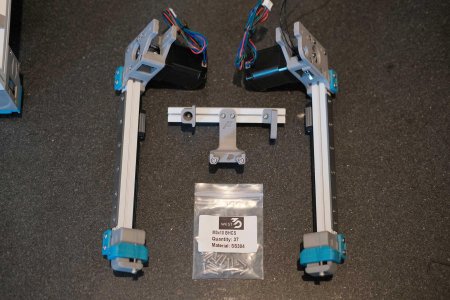
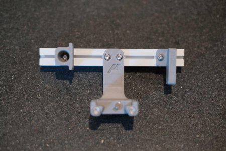
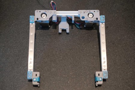
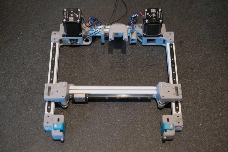
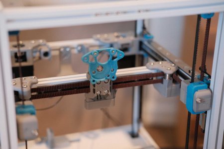
Gantry - Mounting A/B Idlers & Drives

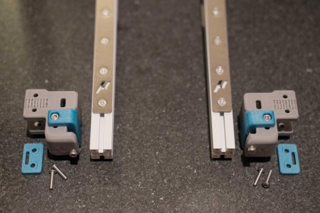
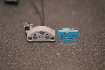
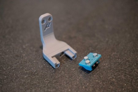
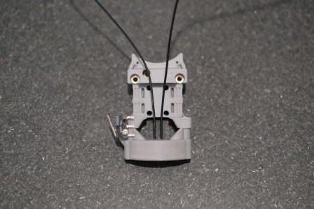
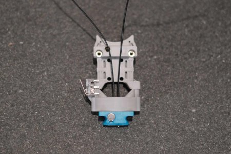
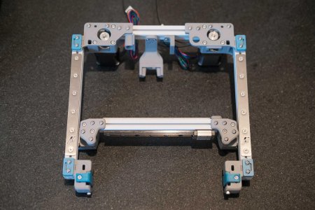
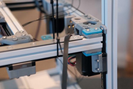
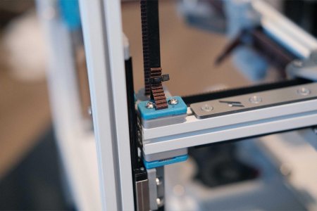
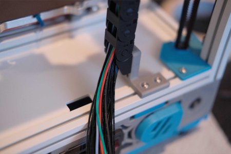
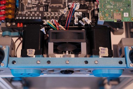
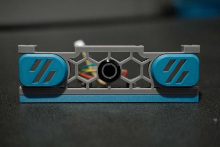
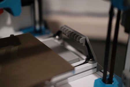
The belt clamps have a recess to accept the belt. That should face downwards. The belt tensioners should have the heads of their SHCS on top.
 

Attachments

  • micron-26-ab-idlers-1.jpg
    micron-26-ab-idlers-1.jpg
    281.4 KB · Views: 53
  • micron-26-ab-idlers-2.jpg
    micron-26-ab-idlers-2.jpg
    246.7 KB · Views: 50
  • micron-27-ab-drives-1.jpg
    micron-27-ab-drives-1.jpg
    321.3 KB · Views: 56
Klicky

You don’t need this many 6x3 magnets. Probably. The switch leads just poke through the printed piece and touch the magnets. Passes my multimeter continuity test.

On the carriage mount, you can see how the magnets press into the exposed wires, completing the circuit when the probe is grabbed. The two wired magnets are the same polarity, while the non-wired magnet is opposite.
 

Attachments

  • micron-28-klicky-1.jpg
    micron-28-klicky-1.jpg
    357.3 KB · Views: 54
  • micron-28-klicky-3.jpg
    micron-28-klicky-3.jpg
    255.1 KB · Views: 47
  • micron-28-klicky-2.jpg
    micron-28-klicky-2.jpg
    227.9 KB · Views: 45
  • micron-28-klicky-4.jpg
    micron-28-klicky-4.jpg
    296 KB · Views: 43
  • micron-28-klicky-5.jpg
    micron-28-klicky-5.jpg
    380.2 KB · Views: 43
Rear Gantry

I’m using leftover 10x11 cable chain, so the mount here is not the default Micron one.
 

Attachments

  • micron-29-rear-gantry-1.jpg
    micron-29-rear-gantry-1.jpg
    307.9 KB · Views: 38
  • micron-29-rear-gantry-3.jpg
    micron-29-rear-gantry-3.jpg
    377.8 KB · Views: 35
  • micron-29-rear-gantry-2.jpg
    micron-29-rear-gantry-2.jpg
    272.2 KB · Views: 35
  • micron-29-rear-gantry-4.jpg
    micron-29-rear-gantry-4.jpg
    363.9 KB · Views: 39
Mounting X Axis
 

Attachments

  • micron-30-gantry-x-axis-1.jpg
    micron-30-gantry-x-axis-1.jpg
    388.6 KB · Views: 37
  • micron-30-gantry-x-axis-2.jpg
    micron-30-gantry-x-axis-2.jpg
    352.6 KB · Views: 36
X/Y Belts

None of the screws holding parts to aluminum rails are tightened yet. Pulling on the belts too hard at this point will case things to shift. We’ll do final tightening of screws and belt once the gantry is installed.
 

Attachments

  • micron-31-xy-belts-2.jpg
    micron-31-xy-belts-2.jpg
    383.3 KB · Views: 36
  • micron-31-xy-belts-1.jpg
    micron-31-xy-belts-1.jpg
    304.5 KB · Views: 38
Mini Afterburner

The little PTFE tube here is the wrong length. I cut it to have 7mm exposed from the printed part as shown in the manual, but this is way too short for the Dragonfly that came with the DFH kit. I later inserted the PTFE tube into the Dragonfly from the top, then measured and cut ~8mm of extension; the 7mm as requested plus a tiny bit to sit inside the printed part for alignment.

Additionally, the drive gear shaft was sticking proud about 1mm and I was worried it would rub against the extruder motor, so I spent some time with a file and knocked it down until it was flush with the printed face.

At first, I had all my fan wires exiting the wire groove, but this required wrapping the left part cooling fan wires around the hotend on the inside of the mount. I changed this after the photo, and just left the fan wires on the left to come out that same side.

Look at how tiny those wires are. Makes standard fan wires look bulky in comparison.
 

Attachments

  • micron-32-mini-ab-1.jpg
    micron-32-mini-ab-1.jpg
    348.3 KB · Views: 41
  • micron-32-mini-ab-2.jpg
    micron-32-mini-ab-2.jpg
    351.8 KB · Views: 40
  • micron-32-mini-ab-3.jpg
    micron-32-mini-ab-3.jpg
    301.3 KB · Views: 42
  • micron-32-mini-ab-4.jpg
    micron-32-mini-ab-4.jpg
    319.5 KB · Views: 43
  • micron-32-mini-ab-5.jpg
    micron-32-mini-ab-5.jpg
    360.8 KB · Views: 49
Gantry Install

The gantry is just sitting on the linear rail carriages here to make sure everything lines up decently. Take the gantry back out and secure the Z belts to the undersides of each corner. Get it “flying” with zip ties.
 

Attachments

  • micron-33-gantry-install-1.jpg
    micron-33-gantry-install-1.jpg
    238.1 KB · Views: 51
  • micron-33-gantry-install-2.jpg
    micron-33-gantry-install-2.jpg
    254 KB · Views: 47
  • micron-33-gantry-install-3.jpg
    micron-33-gantry-install-3.jpg
    274.9 KB · Views: 43
Z Belts

The Z belts should be secured with the bottom clamp, feeding in towards the chamber. Route it down through the Z assembly pulleys, back up through the slot in the X/Y tensioners (just passing through, not actually interacting with the X/Y parts), through the top idlers, and back down to be secured with the top clamp.

Extra belt slop can be fed through the “mouth”. Tightening this clamp down will pull the belt just a bit tighter. It will take trial and error and adjusting one or two teeth at a time to get the 4 corners at equal tension.

I left enough belt length to work with in the future. Finally, zip tie to tidy up.
 

Attachments

  • micron-34-z-belts-1.jpg
    micron-34-z-belts-1.jpg
    183.1 KB · Views: 41
  • micron-34-z-belts-3.jpg
    micron-34-z-belts-3.jpg
    186.1 KB · Views: 39
  • micron-34-z-belts-2.jpg
    micron-34-z-belts-2.jpg
    198.2 KB · Views: 35
X/Y Belts Revisited

Now’s the time to pull the X/Y belts snug, doublecheck for squareness, check for binding/racking in the moveents, tighten up the gantry frame, and cut the belts to length. Flush enough to make me nervous. Also, getting the belt snug enough for the tensioners to set final tension was actually pretty tricky.
 

Attachments

  • micron-35-xy-belts-1.jpg
    micron-35-xy-belts-1.jpg
    196.2 KB · Views: 31
  • micron-36-all-belts-done-1.jpg
    micron-36-all-belts-done-1.jpg
    216.2 KB · Views: 35
Mini Afterburner Revisited

Install the toolhead mount. Test-fitting the toolhead. (I still haven’t cut the toolhead wires to length yet.)
 

Attachments

  • micron-37-mini-ab-1.jpg
    micron-37-mini-ab-1.jpg
    219.5 KB · Views: 35
  • micron-37-mini-ab-2.jpg
    micron-37-mini-ab-2.jpg
    238 KB · Views: 40
Front Skirt

These use the easier-to-print Z motor covers, though I did print the originals and they came out just fine. Spend the time to orient the seam to sit at the bottoms.

Woooo, finally! Still a rat’s nest of wires, but seeing the final colors together is exciting!
 

Attachments

  • micron-38-front-skirt-1.jpg
    micron-38-front-skirt-1.jpg
    335.4 KB · Views: 41
  • micron-38-front-skirt-2.jpg
    micron-38-front-skirt-2.jpg
    279.4 KB · Views: 36
  • micron-38-front-skirt-3.jpg
    micron-38-front-skirt-3.jpg
    211.3 KB · Views: 41
Electronics

AC goes on on the left, DC exits on the right. This lever locks the hinged frame to the aluminum rail. (I later reprint this in Electrolytic Deuterium to make it stand out more.)

The boomerang-looking part is the elevated standoff to mount one corner of the Octopus.

The PSU mounts underneath the already installed hinge.

The Octopus mounts on top of the PSU. The right side mounts of the Octopus have extra printed parts to secure the Pi with self-tapping screws.
 

Attachments

  • micron-39-electronics-1.jpg
    micron-39-electronics-1.jpg
    381.7 KB · Views: 41
  • micron-39-electronics-2.jpg
    micron-39-electronics-2.jpg
    394 KB · Views: 35
  • micron-39-electronics-3.jpg
    micron-39-electronics-3.jpg
    437 KB · Views: 33
  • micron-39-electronics-4.jpg
    micron-39-electronics-4.jpg
    415.2 KB · Views: 38
  • micron-39-electronics-5.jpg
    micron-39-electronics-5.jpg
    266.8 KB · Views: 53
  • micron-39-electronics-6.jpg
    micron-39-electronics-6.jpg
    297.5 KB · Views: 68
Wiring

The mains wires are routed underneath the PSU, coming out on the right and into the AC side of the PSU. The bed wires (heater and two thermistors) are fed into the center hole.

Bed heater wires (white) are installed on the lower left. The bed thermistors are installed in the center (red and blue).

The DC side of the PSU are +/+/−/−, so make sure to keep proper polarity. And I’m jumpering from the second pair to the third pair on the Octopus. I’ve seen people stack spade connectors, but this looks cleaner to me.

A quick test now that AC/DC is all hooked up. We have lights!

The four Z motors are fed up to the top of the hinge, cut to length, and re-crimped.
 

Attachments

  • micron-40-power-inlet-2.jpg
    micron-40-power-inlet-2.jpg
    293.3 KB · Views: 63
  • micron-40-power-inlet-1.jpg
    micron-40-power-inlet-1.jpg
    208.3 KB · Views: 51
  • micron-41-bed-1.jpg
    micron-41-bed-1.jpg
    180.1 KB · Views: 48
  • micron-41-bed-2.jpg
    micron-41-bed-2.jpg
    179.7 KB · Views: 45
  • micron-42-dc-1.jpg
    micron-42-dc-1.jpg
    382.8 KB · Views: 50
  • micron-42-dc-2.jpg
    micron-42-dc-2.jpg
    206.8 KB · Views: 46
  • micron-42-dc-3.jpg
    micron-42-dc-3.jpg
    318.9 KB · Views: 45
  • micron-42-dc-4.jpg
    micron-42-dc-4.jpg
    371.1 KB · Views: 46
  • micron-43-z-motors-1.jpg
    micron-43-z-motors-1.jpg
    323.6 KB · Views: 52
Mini Afterburner Revisited

Eyeballed the wire lengths so that the connectors all sit behind the extruder motor. On the far right, you can see the 4 tiny wires of the Delta hotend fan spliced to normal guage wires and split to two 2-pin connectors.

It’s a lot of connectors with nowhere to hide them.

This is a rear shot of the X carriage mount to show how I routed the X limit switch and probe wires. X limit switch feeds through the center hole and to the left to join the wires on that side, while the probe switch feeds to the right and joins the wires on the opposite side.

The rear side of the mini Afterburner assembly has two zip tie points. Arrange the wire-bundles accordingly, and secure them with zip ties. I am trying to hide the extruder motor’s 4-pin Microfit connector behind the wires. Lol.

Run the wires through the umbilical sheathing and the outer part of the cable gland. Here you can see how full the cable gland inlet is. I don’t think I could fit even one more FEP wire. It’s pretty tough to keep all the wires untangled.
 

Attachments

  • micron-44-mini-ab-1.jpg
    micron-44-mini-ab-1.jpg
    267.4 KB · Views: 50
  • micron-44-mini-ab-2.jpg
    micron-44-mini-ab-2.jpg
    205.4 KB · Views: 49
  • micron-44-mini-ab-4.jpg
    micron-44-mini-ab-4.jpg
    228.1 KB · Views: 42
  • micron-44-mini-ab-3.jpg
    micron-44-mini-ab-3.jpg
    183.5 KB · Views: 43
  • micron-44-mini-ab-5.jpg
    micron-44-mini-ab-5.jpg
    229.5 KB · Views: 41
  • micron-44-mini-ab-6.jpg
    micron-44-mini-ab-6.jpg
    213.1 KB · Views: 41
  • micron-44-mini-ab-7.jpg
    micron-44-mini-ab-7.jpg
    208.1 KB · Views: 43
  • micron-44-mini-ab-8.jpg
    micron-44-mini-ab-8.jpg
    227.5 KB · Views: 41
  • micron-44-mini-ab-9.jpg
    micron-44-mini-ab-9.jpg
    231.6 KB · Views: 39
Umbilical/Cable Chain

I might have accidentally forgot to take photos while maneuvering wires through the cable chain. It’s leftover 10x11 chains from my Trident build with redesigned mounting parts to fit the 3-hole screw pattern common to generic brands.

Also, the A/B motor wires were too short to actually reach the controller board, so I opted to cut them here before the chain to extend them.
 

Attachments

  • micron-45-umbilical-chain-1.jpg
    micron-45-umbilical-chain-1.jpg
    229.4 KB · Views: 45
  • micron-45-umbilical-chain-2.jpg
    micron-45-umbilical-chain-2.jpg
    191.3 KB · Views: 44
Wiring (continued)

Final stepper motors connected: blank, A, B, blank, E, Z0, Z1, Z2, Z3.

Here’s a shot of the electronics before I stack the Raspberry Pi.

Powering the Raspberry Pi with 2x 5V and GND from the Octopus to the GPIO header.

USB-C for data connection. Then flip the Rasbperry Pi over and secure with self-tapping screws.

Wiring complete!
 

Attachments

  • micron-46-ab-extruder-motors-1.jpg
    micron-46-ab-extruder-motors-1.jpg
    356.1 KB · Views: 45
  • micron-48-pi-1.jpg
    micron-48-pi-1.jpg
    421.2 KB · Views: 45
  • micron-47-wiring-1.jpg
    micron-47-wiring-1.jpg
    373.7 KB · Views: 44
  • micron-48-pi-2.jpg
    micron-48-pi-2.jpg
    402.7 KB · Views: 44
  • micron-49-wiring-1.jpg
    micron-49-wiring-1.jpg
    257.2 KB · Views: 50
  • micron-49-wiring-2.jpg
    micron-49-wiring-2.jpg
    305.6 KB · Views: 56
Last edited:
Initial Build Complete

*Tears up
 

Attachments

  • micron-1.jpg
    micron-1.jpg
    315.4 KB · Views: 54
  • micron-2.jpg
    micron-2.jpg
    365.4 KB · Views: 52
Neopixel Front Button

The Micron is headless and neopixel-less up to this point. To bring back some utility, I added a Chromatek 19mm Momentary Push Button. The built-in neopixel will work as a status indicator and the button will cycle through the same preheat macros that my Trident has (60C for PLA → 110C for ABS → 0C for idle).

The wiring is not complicated, but to make it fit, I had to give up the included harness and extend the electronics fan arms 10mm. You have the same 3 wires (5V in, data in, and ground) that Stealthburner neopixels have, and you have the same 2 wires (NC and ground) that limit switches have.

I had to make sure to bend the spades a bit extra so that the wires clear the spinning fan.
 

Attachments

  • micron-50-neopixel-front-button-1.jpg
    micron-50-neopixel-front-button-1.jpg
    243.7 KB · Views: 50
  • micron-50-neopixel-front-button-2.jpg
    micron-50-neopixel-front-button-2.jpg
    305.4 KB · Views: 42
  • micron-50-neopixel-front-button-3.jpg
    micron-50-neopixel-front-button-3.jpg
    203.3 KB · Views: 41
  • micron-50-neopixel-front-button-5.jpg
    micron-50-neopixel-front-button-5.jpg
    276.4 KB · Views: 36
  • micron-50-neopixel-front-button-4.jpg
    micron-50-neopixel-front-button-4.jpg
    246.3 KB · Views: 38
  • micron-50-neopixel-front-button-6.jpg
    micron-50-neopixel-front-button-6.jpg
    224.3 KB · Views: 37
  • micron-50-neopixel-front-button-7.jpg
    micron-50-neopixel-front-button-7.jpg
    224.3 KB · Views: 41
  • micron-50-neopixel-front-button-8.jpg
    micron-50-neopixel-front-button-8.jpg
    233.8 KB · Views: 42
Panels

I lined the rear and top panels with 1mm foam tape and they worked perfectly fine with the stock clips, but I lined the side panels with 3mm foam tape to provide clearance for the linear rail carriages, and these required making the stock clips 2mm deeper. I also flipped the front door 180° and opted to not VHB the handle just yet. Front door has no foam tape because it would affect the action of the hinge.

Fully enclosed and printing ABS!
 

Attachments

  • micron-51-panels-1.jpg
    micron-51-panels-1.jpg
    251.5 KB · Views: 50
Neopixel Sticks for Chamber Lighting

Smaller versions of Eddie’s 2020 LED mounts exist for 1515, but having the LEDs mounted so high will cause the toolhead to always cast its shadow onto the model and bed. Trying something new, I’ve mounted two Neopixel Sticks low and near the bed. I tried to chain them to the front push button, but figured out that RGBW and RGB cannot be chained together.
 

Attachments

  • micron-52-neopixel-sticks-1.jpg
    micron-52-neopixel-sticks-1.jpg
    253.4 KB · Views: 49
  • micron-52-neopixel-sticks-2.jpg
    micron-52-neopixel-sticks-2.jpg
    227.7 KB · Views: 45
  • micron-52-neopixel-sticks-3.jpg
    micron-52-neopixel-sticks-3.jpg
    211 KB · Views: 46
  • micron-52-neopixel-sticks-4.jpg
    micron-52-neopixel-sticks-4.jpg
    199.1 KB · Views: 41
  • micron-52-neopixel-sticks-5.jpg
    micron-52-neopixel-sticks-5.jpg
    173.7 KB · Views: 54
Top