What's new
VORON Design

Register a free account today to become a member! Once signed in, you'll be able to participate on this site by adding your own topics and posts, as well as connect with other members!

LDO Voron 2.4 Build with All Metal Parts

MichaelOToole

Well-known member
General remarks re LDO kit, and ChaoticLab CNC Metal Parts...
Also includes general questions & answers relating to getting printer up and running...


The CL (CharticLab) kit is top notch but quite expensive, even so, every single part was perfect not even a single blemish.
The LDO kit was 99.9 % perfect, only a couple of the pulleys/idlers slug threads were iffy.

If I make another Voron I will choose something less expensive, perhaps the FYSETC version as it's half the price and reviews Iv'e seen are quite good.
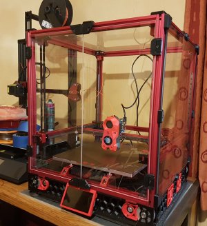
The Build:
Main reference: Voron 2.4 CNC parts Kit Build Guide (here) as my main reference, switching to the LDO Voron Build Guide for a cross reference.

As far as I can tell at this stage*, I only need to print cosmetic parts such as the skirting thingy to complete the project.
Some parts will be duplicated for example you will end up with a few spare bearings and lots of nuts and bolts.
One minor issue was a reference to M3x28 bolt sizes in the CL box, it was actually M3x27 (1mm smaller that referenced)...

VoronBuild.jpg

That's all for now, will keep track of next section and post anything of interest, I Just wanted to mention the quality of both kits is excellent, if a little pricey ...

* please check later posts for updates...

Notes: 22 March 2024
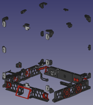
Check the top aluminium part (blue in image below) that locks the Z belts in place, make sure these are horizontal (parallel to the bottom part and not at an angle).
On my build, the M5x16mm screws were a bit too long, bottoming out before fully securing the belt leaving them angled, the front belts slipped.
As I didn't have shorter bolts, I added a 1.5mm washers for each... that did the trick...

BeltTensioners2.png


Notes: 23 March 2024
In software you will/may need to flip the 4.3" TFT Display


1: Open config.txt file on SD card...
2: Find and Comment out dtoverlay=vc4-fkms-v3d, if not already done... add a # at start of line
3: Add these lines to end of file:
display_lcd_rotate=2
dtoverlay=rpi-ft5406,touchscreen-inverted-x=1,touchscreen-inverted-y=1
4: Replace SD card and test, the display should now be correct...
Reference Doc here...
 

Attachments

  • VoronCurrent.jpg
    VoronCurrent.jpg
    1,023.6 KB · Views: 12
Last edited:
As far as I can tell at this stage, I only need to print cosmetic parts such as the skirting thingy to complete the project.

Thank you, that actually answers a question I had a while back. (Whether the CNC kit was enough to complete the motion system.)
 
@Dave32, it appears that way... as can be seen on the image, but, I still have to add a six small parts and some red shims and of course the belts. I'm guessing it's designed to get to the stage where I can print the rest, that would make sense...

I did miss one important notes, the Chaotic Lab PDF does indicate what parts they include are in Blue and parts from the 2.4 kit are indicated in Red.
It might be as well I misses this, as there were no F725 bearings included but a different type similar to MiSUMi Stainless Steel Grooved Bearing V-Groove or possibly 625ZZ or 625VV were, so I used them.

Actually, 625ZZ look more likely...
The shaft could have been 1 or 2 mm longer with these, but if I have any issues, I will swap them out with F625 (F = flange) bearings...
Mike
 
Last edited:
Day 2 of Build

Today I just ran the belts and apart from running one of the Z axis belts slightly wrong (no wonder it was stiff), every thing went according to plan.

The aluminium carriage in the Kit was a nice upgrade (by its self it would be worth while).
Carriage.png
Just realized, I wont be using the aluminium carriage, I have the ChaoticLab's CNC Tap...
I guess I could upgrade another printer with all the spares I have .

The appears to allow additional adjustment...
Tensioner.png

carriage_cnc2.jpg
 
Last edited:
Might need some printed parts?

X/Y End-Stop housing print (for End Stop Board, the one with two micro-switches)...
Z End-Stop housing print (for End Stop Bard, the one with a single micro-switch)...

My aim here is to identify and document the parts that are required to complete the build (for those who went with the CNC kit parts option) and give approximate cost based on quotes I get and supply link to those suppliers.

List of printed parts required:

Required (Full Build without Skirt)
  • X/Y End-Stop housing (1)
  • Z End-Stop housing (1)
  • Z belt covers (4)
  • All Panel Hinges fixings (?)
  • Doors hinges (6 outer, 4 inner, 2 latch parts (parts with magnets)
  • All Panel Clip
  • DIN Clip (3)
  • RS25 Bracket (1)
  • Octopus Bracket Set
  • PSU Stabilizer
  • Raspberry Pi bracket
  • Irs 200 PSU bracket (2)
  • Wago 221-415 mount3 (5)
  • LCD Faceplate (BTT TFT 4.3)
  • LCD Mount (BTT TFT 4.3)
Option (Minimum Build to get started as per Dave32's Suggestions)
  • Build without LCD (Klipper runs perfectly fine without an LCD, you can control the printer via the web interface).
  • Omit the Z endstop and configure Klipper to use the Z probe as a virtual endstop.
  • Use sensorless homing in lieu of installing the X/Y end stops.
  • The panels could be taped in place, the Z belt covers omitted, the Raspberry Pi could be external.
Cosmetic (print later)
  • Skirt (all pieces)
Hot-End (Assembly Options)
  • I bought a full kit in ABS for StealthBurner with specific parts for my hot-end, would recommend you do the same.
Filter:
  1. Exhaust Filter Assembly
  2. (or/optional) Nevermore Parts
Updates:
Got a couple of quotes for the remaining parts, in the ball park of €85. (I missed a few, it may cost a little more).

Mike
 
Last edited:
If you're planning on using the inductive probe, you won't be able to use that mount. They changed the manual to the correct one, but the mount itself is still designed for the old one that's no longer used. Looks like you're planning on using their CNC Tap though, which means you shouldn't have to worry about this!
 
I switched the mount to the CNC Tap V2, it looks awesome.

I will reuse the CNC mount (and all the spare parts I have) to complete an unfinished 400x400mm fixed bed printer I designed years back but never finished...
I could turn it into a Voron :)
 
Last edited:
Image of parts required to complete build if using CNC kit parts:

Imported from original CAD into FreeCad, I used the 300mm parts.
Note the LCD enclosure for the larger LCD has yet to be added, I guess the larger LCD is a mod?

This image does not include panel hinges fixings or BTT LCD parts (attached does).
Voron_Required_Parts.jpg

Mounting Brackets:
Spider Control Board: lrs_200_psu_bracket_x2.stl + Spider_bracket_set.stl
5 Volt Supply (Meanwell): rs25_psu_bracket.stl
Raspberry Pi: pcb_din_clip_x3.stl + raspberrypi_bracket.stl
Main Power Supply: pcb_din_clip_x3.stl +

The image is missing the two Brackets for the main Power Supply - Part: (pcb_din_clip_x3.stl)
 

Attachments

  • All-parts-required.png
    All-parts-required.png
    102.2 KB · Views: 29
Last edited:
If it helps, quite a few of those parts in your "required" list wouldn't actually hold up printing if you didn't have them.

For example, Klipper runs perfectly fine without an LCD, you can control the printer via the web interface. Likewise, you could omit the Z endstop and configure Klipper to use the Z probe as a virtual endstop... and use sensorless homing in lieu of installing the X/Y end stops. The panels could be taped in place, the Z belt covers omitted, the Raspberry Pi could be external, etc, etc.

I'm certainly not saying you should do those things... just that if you are in a "bootstrap" situation without an ABS-capable printer, you have some options.
 
Sometimes you don't see the trees for the woods ;)

I actually ran my Ender 3 with Clipper (headless) but it didn't dawn on me to do that with my build.
Your suggestions make perfect sense, I could make a short term enclosure to print parts I need in ABS and use PLA for parts in the electronics bay area.

I could then updated these parts later if required... it must be possible/feasible to use PLA in the base, theoretically nothing should ever get hot there right?

Mind you I just ordered most of the parts I need but I guarantee I missed some...
I edited "required" post above to include your suggestions, they make perfect sense...

Thanks Dave...

I was tempted to say: "Sorry Dave I'm afraid I can't do that" ... have always wanted to use that quote :)
 
Last edited:
while metal parts means you can really push your machine but does having metal to metal part connection joins add resonance ?
the abs plastic parts while they might not be as strong as metal equivalents can they be better when it comes to resonance ?
can some one please help me understand this better.
I cannot say from experience but I am adding Metal AB joints XY and two more motors to A1 and B1 so I can run some tests but I think the metal will add some very high frequency to input shaper but you won't really see that in the prints as much as a low frequency.
 
I cannot say from experience but I am adding Metal AB joints XY and two more motors to A1 and B1 so I can run some tests but I think the metal will add some very high frequency to input shaper but you won't really see that in the prints as much as a low frequency.
Do share how it goes. I would love to hear your analysis of this.
 
while metal parts means you can really push your machine but does having metal to metal part connection joins add resonance ?
the abs plastic parts while they might not be as strong as metal equivalents can they be better when it comes to resonance ?
can some one please help me understand this better.
It is hard to know without testing. The metal parts are CERTAINLY more rigid. The added rigidity should help a lot. But on the other hand, these Voron printers are mostly made of 2020 extrusion with little bits of plastic added here and there. Using CNC'd parts means that now the printer is made from 2020 extrusions with little bits of metal added here and there. It is still basically the same thing. To see a very different result, you would have to change out the parts that matter the most, the 2020 extrusions.
 
It is hard to know without testing. The metal parts are CERTAINLY more rigid. The added rigidity should help a lot. But on the other hand, these Voron printers are mostly made of 2020 extrusion with little bits of plastic added here and there. Using CNC'd parts means that now the printer is made from 2020 extrusions with little bits of metal added here and there. It is still basically the same thing. To see a very different result, you would have to change out the parts that matter the most, the 2020 extrusions.
thanks for sharing your perspective.
 
Every structure has resonance, the aim is to design so that at operation, resonances don't occur, or, are at a minimum at the frequency of operation.
Plastic parts are better at damping resonance especially where interconnections occur, but are prone to failure, breakage and deformation.

The CNC parts represent a good compromise, adding structural strength where necessary, are they actually needed? not really, are they better suited for purpose? yes...

Besides all this, the combined Red and Black Anodized Aluminum looks really cool :cool:
 
Just updating my progress 23 March 2024.
Electronics installed and wired...
Octopus and Pi flashed using defaults...

As I'm using Tap, I don't need Z end-stop, is that correct?
Also, not using X and Y end-stops, using 2209's with sensor-less homing?
Basic printer.cfg done... Mainsail Dashboard, no errors reported... looking good so far...

Eric Zimmerman: Voron24, VoronTools
Initial Startup Checks
 
Last edited:
Correct you should not need the Z endstop if using TAP.
Sensor-less is great, just don't skip any steps in tuning it to make sure it's very repeatable. Something I don't see mentioned in any sensor-less tuning is if you need to, adjust your run current and or speed of homing to make it perfect.
 
Status on Build 30th March 2024
  • Electronics & Wiring: Completed...
  • CANBus: EBB SB2209 CAN (RP2040) - Programmed, working...
  • CANBus: U2C - Programmed... *working...
  • BED and Thermistor: Tested, working...
  • Stealthburner : Heater & Thermistor tested & working...
  • Motors: All working after some *issues...
Issues so far:
* Lots of fun getting CANBus working especially the U2C board, down to lack of knowledge and mixed resource with conflicting information...
* It appears I may have a fault on Motor_5 driver (Z3) on my Octopus 1.1, switched everything to Motor_6, modified pins assignments and it works fine...

Next the extruder...
 
Last edited:
Status on Build 30th March 2024
  • Electronics & Wiring: Completed...
  • CANBus: EBB SB2209 CAN (RP2040) - Programmed... Working...
  • CANBus: U2C - Programmed... Working (after hours)...
  • BED and Thermistor: Tested, working...
  • Stealthburner : Heater & Thermistor tested & working...
Extruder: next step...
Motors: next step...

Lots of fun getting CANBus working especially the U2C board...
I will be setting CAN for my trident build this week as well. Pi - U2C - EBB 36 - Dragon Burner
 
Top