What's new
VORON Design

Register a free account today to become a member! Once signed in, you'll be able to participate on this site by adding your own topics and posts, as well as connect with other members!

LDO Voron 2.4 Build with All Metal Parts

Here we go...
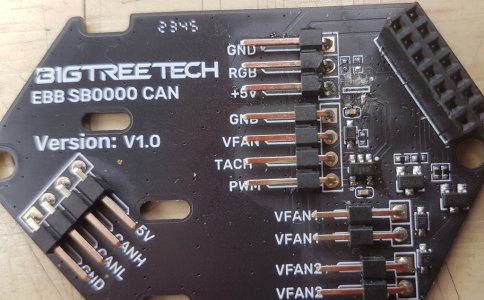
blister.jpg
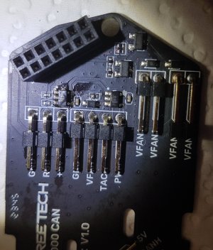
Blistered IC...

felloff.jpg
Component fell off this one, it was not damaged or marked, the damage is from my poor attempt to re-seat the component with poor eyesight and no optics.
I do have the necessary equipment (trinocular microscope) but no room to set it up and I am a pretty good solderer after 45 years of doing it...

Again in hindsight, I should have tested the component before re-soldering it, it was probably faulty by then...
I've ordered 10 replacement buffers, best get out my microscope, it hasn't had any work this year... :giggle:
 
Last edited:
Hmm...
Is there any chance that the "RGB" line is shorted? (Not on the PCB, but on your string of LEDs.)
 
I checked the board and the leds four times, no shorts... besides, it has a 100Ω resistor on the output, that would pretty much prevent blowing the device (assuming a if 5V supply), also, the third board worked perfectly and is still working. The only way I see to cause this damage is if I connected the connector up one place, that would result in the chip/buffer getting 24V...

It's a bit of a mystery...
 
besides, it has a 100Ω resistor on the output, that would pretty much prevent blowing the device (assuming a if 5V supply)
I did see that... it seems like a poor component choice though. The IC is only rated for 50mA of current as the "absolute maximum" - and in a short circuit condition that could easily be exceeded due to the standard tolerances (5-10% is common) on the resistor. In truth, 50mA is a LOT of current for a data line... they probably should have selected a different resistor value to keep that fault current a bit lower.

The only way I see to cause this damage is if I connected the connector up one place, that would result in the chip/buffer getting 24V...
Could be! It's too bad they didn't key the connectors to prevent this from happening...
 
Could be! It's too bad they didn't key the connectors to prevent this from happening...
My exact thoughts, I believe a keyed version exists, I'm sure I saw one previously, exact pin count and pitch...
I did scope the signal, a schmitt trigger is definitely required...

As there's a the 100 ohm limiting resistor, the buffer must source, but even so, 20-30mA should be enough for these leds.
The resistor could be increased to 150-180 ohms but the best solution would be a keyed connector...
 
Extra Fans
As the skirt will accommodate two additional 60mm fans, I purchased and installed two NF-A6x25 FLX fans. Needless to say they are quiet, very quiet...
It's time to update the default 60mm fans...

I should add, I've gone from noisy to quiet with a few simple changes to fan speeds and some damping. I can now print in the same room without getting a headache... :whistle:
 
Last edited:
I may have forgotten to post an update on this, the new SB0000 replacement worked flawlessly, I was extra careful during assembly/alignment...

Over the past three months, If a print stick, it prints flawlessly...
When printing the same part in PLA using exact same slicer settings, sometimes I have no stringing, sometimes a little, and other times a lot ... another mystery...
 
Thoughts after building Voron 2.4 Rev C and spending almost six months with it...

Was it worth the money?

Being an all metal build cost including metal Tap and both sets of tensioners, plus additional plastic parts and other spares cost: €2000
There's no doubt I could get comparable results from a commercial printer for less investment but I would not have full control over the hardware or software.

Was it worth the effort?
Absolutely, I learned a great deal from this build, I have no regrets whatsoever...

Things that stand out:
Quad gantry leveling, ChaoticLab's Tap, E3D Revo Hotend (LDO Edition), LDO's Bed Quality, Voron design and attention to detail and community support...

Essential Upgrades (4 me):
ChaoticLab's Tap v2, I just like it...
CANBus, adds to build complexity but absolutely wort it...

tbc...
 
Last edited:
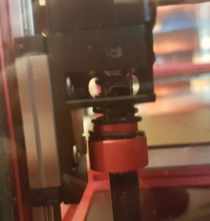
Can you post a picture of your z joints from the side? I was curious to see what the spacing looks like with the adjustable z joints. The chaotic lab GitHub has no mention on how tight or loose they should be. I have looked and cannot find anywhere where someone mentions how tight the springs should be.
 
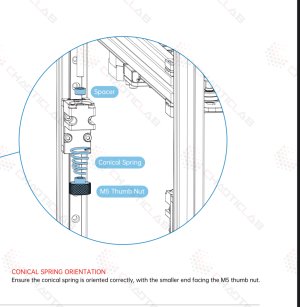
I was speaking of the actual Z-joints with the conical springs. Not the actual tensioners. Like in this picture.
 

Attachments

  • IMG_1671.jpeg
    IMG_1671.jpeg
    429.8 KB · Views: 18
My apologies I misunderstood...
Here is the picture, I tightened these to about 1/3 of the shaft length, just enough provide tension... max would be half way....
20240617_192707.jpg
 
Last edited:
Awesome description of a good upgrade IMHO. I still would like to see something slightly larger in the corners to ensure squareness/perpendicularity and rigidity, but I am a traditional machine builder so that stems from solid cast iron frames and 50 mm thick slabs of steel as a base:cool:

Also I saw your comment on bolts being 27mm instead of 28mm, I found this a sure sign of dealing with Chinese hardware. 27 mm is not a standard so it was simply meant to 28mm I think. So when that happens be aware of sloppy Allen key fits and sometimes even undersized outer thread diameters (will strip quickly). I try to avoid them these days. I have 100s if not thousands of pieces passing my hands every week at work and for my hobby, the hassle is not worth it.

Looking forward to see this thing printing, I will be looking out for that. (y)
 
I recently saw the all metal cnc kit and was wondering how that would work out. Thank you for the updates and information!
 
@3dCase, On another build, prior to finding Voron, I designed a 500x500mm frame with a fixed bed. I used 20x20mm and 20x40mm extrusions with 4mm triangular supports in the top and bottom corners. It was considerably stronger and stiffer than my Voron but most certainly over engineered unless you need a very large printer.

My final design ended up being a 400 cube frame with a fixed bed using both 20x20mm and 20x40mm extrusion, which I still have. I never got around to finishing it. It might make a nice Voron down the road when I have the spare cash to buy another CNC kit plus the other parts...

Mike
 
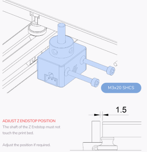
Hi MichaelOTool, I seem to have pretty much the same rig as you. I have it built but still working out the specific (definitely bit off about as much as I could chew). I have a questions regarding the Nozzle Probe that sits under the bed. The instruction show a long shaft but the package came with a shorter shaft as well? The bed sill not fit on with the longer shaft so I am assuming I should use the shorter one. Should the shaft touch the bottom of the bed in any way ? And will using a screw to seat the shaft at a particular height matter? Any suggestions will be appreciated. Also, did you have to run the 200Ma 30V blocking diode for the Probe ?
 
Last edited:
With my build I did not use the Diode, it might be down to the control board but I guess it wasn't required or is already present on the BigTreeTech Octopus V1.1
I used Tap and set up and used endstop_pin: probe:z_virtual_endstop in the config, so didn't need the endstop probe and its shaft. I also used endstop_pin: tmc2209_stepper_x:virtual_endstop to avoide the need for the x/y endstops, this worked a treat...

Otherwise, the 5x?mm shaft appears to be a couple of mm above the bed and at least 1.5 mm from touching the bed (see image attached)...
I would imagine the probe should activate when shaft is level with bed height, lower the gantry until nozzle touched bed, then move to probe and adjust so it triggers at that height.
There may be instructions for this in the build pdf...

endstopshaft.png
I do remember there were two shafts but cant remember what the second one was for... will check my notes...

I attached my printer.cfg, probably not perfect but might be useful if you have Tap and want to use it for setting z endstop, and/or, want x and y virtual endstops too...

You would normally start with driver_SGTHRS: set to a higher value say, 250 and then reduce until the x,y end stops triggered gently (without a thud)
Of course if your using actual ens-stops you can ignore these comments ...

Mike
 

Attachments

Last edited:
The manual did indicate the other way round, but when secured, it resulted in a lot more tension than I was happy with.
After reversing them I noticed they sit better, if necessary I could always add a few more turns to achieve similar tension, so I left them reversed...
 
Top