What's new
VORON Design

Register a free account today to become a member! Once signed in, you'll be able to participate on this site by adding your own topics and posts, as well as connect with other members!

My Modified LDO 300 kit build log - updated all the time

Today I spent trying to figure out a way to gracefully SHUTDOWN the LDO 300 kit printer and how to BOOT it back up.

Yesterday when I wanted to shutdown the printer I would have to go to the upper right corner of the Mainsail UI and select shutdown. This gracefully shutdown the raspberry pi which runs the Klipper service but it does not turn off all the power supplies.

I have 10 independent power supplies hooked up for this one printer:

1. The 24V Meanwell PSU
2. a 5.1V 3A PSU for powering the Raspberry Pi 4B
3. a 5V 2A PSU for UGREEN Powered USB Hub. I have a Samsung 870 EVO 500GB SATA 2.5" Internal Solid State Drive (SSD) that I use as the disk drive for the Raspberry Pi and it needs current to run so I had to attach the SSD to a powered USB hub or I would keep getting under voltage warnings
4. I have two WLED QuinUno servers attached to the printer. One WLED server drives 92 RGBW Leds that is inside the chamber enclosure. It needs 5V 15Amp power supply. The first LED is farther away than the bottom RGB light.
5. Along with a separate power supply to drive the RGBW lights I also wanted an separate power supply to power the ESP32 that is the mcu for the WLED server. This way I can turn off the LEDs without loosing the running program. This power supply is 5V 2A.
6. The second WLED QuinUno server controls the Bottom RGB lights (which is two separate strips on two different channels). Combine they only need a 5V 10Amp power supply. I could have gotten away with 10amp on the Chamber lights but I screwed up and used 24AWG wire between the strips. Next time I will know to only use 20AWG wires. I have a combo of 20AWG but for some stupid reason I used 24AWG between the 7 strips in the chamber (do not make this mistake). The Bottom RGB lights I used 20AWG only. I have 24 RGBW leds on the bed pan mod I made and another 102 RGB leds that light up the ground beneath the printer to give is a low rider look.
8. The second WLED server also needed a separate power supply to power the ESP32 mcu controlling the Lights. This is a 5V 2A psu.
9. I wanted to control the WLED servers lights with a IR remote so I had to buy an IR repeater. The PSU for the IR repeater is 5V 1A
10. I have a Humidity sensor inside the enclosed chamber that use to run off of batteries. I did not want to have to go into the printer ever month to change out two 1.5V batteries so I hooked the humidity/temp sensor up to a voltage divider and I am using a 3V 1A psu to power the sensor.

9 out of 10 of theses power supplies are hooked to Sonoff 31 smart power plugs. These Sooff 31 power plugs are running Tasmota firmware. Which means I can use HTTP commands or MQTT commands to control the plugs.

The 24V Meanwell PSU is hooked up to a BIG RED button so I can cut the power to the printer quickly. I do have a
APC BX1500M UPS (1500VA UPS Battery Backup and Surge Protector) for the 24V PSU but I only want to use it for short power looses. Where I live, I loose power a couple a times a week (not for a very long time, it might only be long enough to make the lights blink once or twice). But for 3D printers, loosing power for a second will kill the print job.

So with 10 power supplies, turning off the printer means turning off 10 additional plugs! You also have to turn on 10 additional plugs to power up the printer. I wanted a one button solution!
The Tasmota firmware get me there part way. I can access the power plugs http address but now I have 9 web pages I need to visit.

I worked on a solution for solving my RP2040 communication problem by using a web page to display a button and then behind the screens send the commands to a 5V relay to toggle the USB connection. By doing this work I learned some about AJAX, NGINX, PHP and jquery along with javascript. I endedup with one web page that contained all the other web pages. One step closer to a one button solution.

Yesterday and Today were the days I spent on finding a solution. I also needed away to send a command to Klipper to tell it to shutdown the printer. After looking through the moonraker DOCs site and reading about GET and POST calls thru moonraker to Klipper I start trying to perform the PUT calls. To execute a macro which calls moonraker to shutdown the printer you have to use the POST command. When using POST with XMLHttpRequest() call I keep getting a CORS error. So I went back and looked at my setup for NGINX. You want access to the Tasmota plugs without having the Raspberry Pi that is running Klipper for my printer booted up all the time.

So I have a second Raspberry Pi 4B in my house that I use to communicate with my smart plug but use a separate Raspberry pi for my Klipper service. So to turn off the printer I am making a CORS call (taking between two different IP address). I tried to match the header information up and even when I did get the headers to agree I ended up being stopped by the Klipper service due to a CORS issue.

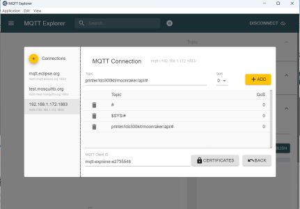
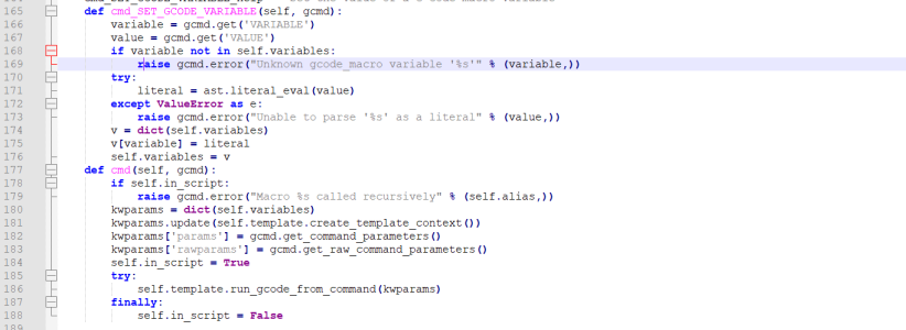
I did some more looking around and then last night it hit me that I should try using MQTT instead of the POST commands. I already had MQTT installed on a raspberry pi but up to this point I was not using MQTT for controlling the Tasmota plugs. I also wanted to control the lights being turned on and off via macros. So I started working on the light macros too.

I investigated using javascript, mqtt client and websockets. I now had the ability to click on an HTTP IP address to a .html file and have the printer turn off the lights and shutdown and wait a couple of 15 seconds before shutting down the power supply to the raspberry pi and the power usb hub.

To BOOT up the printer I wanted to turn on the printer lights and then turn on the power supplies for the powered USB hub and then the power supply for the raspberry pi. I had a HTTP IP address to a .html file that did this exactly.

The last bit took me a while to get working. I wanted a button on my LDO 300 Kit Control web page that I could click that would trigger the shutdown html page and another button that would trigger when I clicked it's button to boot up the printer. For some reason I could not get the button to work. I was using a GET with XMLHttpRequest() call and I was giving it the HTTP address to the file. But for some reason the it appeared that the button was not getting pressed. I had worked thru all the errors and I was using chromes dev console to see the errors but when I stepped thru the code I was not seeing any problems. So I took another look at my .html files that were working. I finally noticed that the .html files were really just pure javascript code. The html file did not have any text fields or data enter fields. So I decided to just call the javascript functions with the AJAX on.click(function() call. Once I did this everything worked.

So I need to learn more html and AJAX PHP and jquery with javascript. I knew it would work I just could not get the stupid button to work with the two html files I had. I suppose a GET request does not work if the file is just javascript. Lesson learned.

So in the end I ended up with two new button at the top of my LDO 300 Kit Control Web page:

1671080530976.png

Problem solved. You can see the code at
 
So the last couple of days I have been working on two things. The first item is to have the ability to shutdown and reboot my machine via a webpage button. The second item is to have a script file that will update all the processors or MCUs on the printer with the latest Klipper firmware without having to insert a micro-SD card or press a small button!

Here is the script file with the "Console_output_update-all.sh.txt" file. The key to developing a script was that I needed to install CanBoot (second stage bootloader) on two of the mcu on my printer. The "Console_output_update-all.sh.txt" file is included in the the attached .zip file named "BASH_file_to_update_ALL_mcu_on_the_printer.zip"


I own a EBB36v1.2 Can Bus tool head board. This toolhead board runs on the CAN bus and when I installed it I had already placed CanBoot onto the device. But that was back during Klipper firmware version 10. Klipper is now at version 11. I needed to update the klipper firmware.

I own a RP2040 (RP2040-zero) that I use for the TinyFan PCB as its microprocessor (MCU). This is the same type of processor that is found on the SB2040 toolhead board. The difference between the two is a lot but the basic difference that I was concerned with was that the RP2040-zero uses the USB bus while the SB2040's RP2040 uses the Can Bus.

So I wondered if the SB2040 can use the CanBoot bootloader could my RP2040-zero use it?

I have been testing out this theory.

I got hold of a spare RP2040-zero and decided to mess with it instead of the working RP2040-zero in my printer.

I learn to install CanBoot bootloader by using the following document: https://docs.google.com/document/d/1yaRNuQxDxqgijE8YeJ2r9tUZgJZ4tXXjmrAiFyAfsek/edit#

It is not a perfect document but it helped me choose the correct "make menuconfig" setup for the Can Boot bootloader install on the RP2040-zero and the Klipper firmware install on that same RP2040-zero.

Here is the screen shot of the my setup for the CanBoot bootloader for the RP2040-zero that will communicate via the USB bus:

Setup for CanBoot Bootloader for RP2040 using USB.jpg


To flash the RP2040-zero with this CanBoot, second stage bootloader, perform the following commands:

Code:
SSH into your printers Klipper server.

cd ~/CanBoot
make clean KCONFIG_CONFIG=config.CanBoot.rp2040                                    #  When you add KCONFIG_CONFIG=<name_of_stored_config_file> make utility will create a new default configuration into the filename
make menuconfig KCONFIG_CONFIG=config.CanBoot.rp2040                               #  force make to save the configuration into the filename
make -j4 KCONFIG_CONFIG=config.CanBoot.rp2040                                      # have make use the configuration file when building the firmware

lsusb                                                                                       # you need to find the ID for the next command, my ID is 2e8a:0003

   my output:
      Bus 001 Device 040: ID 2e8a:0003 Raspberry Pi RP2 Boot


make flash KCONFIG_CONFIG=config.CanBoot.rp2040 FLASH_DEVICE=2e8a:0003                      # flash the RP2040-zero using the named configuration file


If you ever need to reflash the CanBoot bootloader to the RP2040 (which I did), here are the instruction to be able to do that:
Code:
First you must SSH into your Klipper server

cd ~/CanBoot 

lsusb
   my output:
      Bus 001 Device 040: ID 2e8a:0003 Raspberry Pi RP2 Boot

Make note of the ID number
Make note of the name of the device

If you do a "ls /dev/serial/by-id/*" command you will should see something similar to :
ls /dev/serial/by-id/*
   my output looks like this:
         /dev/serial/by-id/usb-CanBoot_rp2040_E0C9125B0D9B-if00

Even after you flash the RP2040-zero with the second stage CanBoot bootloader to overwrite the second stage CanBoot bootloader you will need to place the RP2040 into BOOTSEL mode. 
HOLD down the "BOOT" button while plugging in the USB cable to force the RP2040-zero into BOOTSEL mode.

To Flash the newly recompiled CanBoot bootloader do the following comand:

make flash KCONFIG_CONFIG=config.CanBoot.rp2040 FLASH_DEVICE=2e8a:0003

now do another

lsusb
  my output:
      Bus 001 Device 041: ID 1d50:614e OpenMoko, Inc. rp2040

Make note the ID number has changed (as long as you did not change the USB IDs) during the make menuconfig.
Make note the name has also changed.

By using " lsusb" and "ls /dev/serial/by-id/*" commands you can tell what state your device is in. 

If this name is "Raspberry Pi RP2 Boot" with USB ID of "2e8a:0003", then your RP2040 is in BOOTSEL mode and will have "CanBoot_rp2040" as part of its
/dev/serial/by-id/ name.

If the name is "OpenMoko" with USB ID of "1d50:614e", then Klipper firmware is loaded on the device and will have "Klipper_rp2040" as part of its
/dev/serial/by-id/ name.


Here is the screen shot of the my setup for Klipper firmware for the RP2040-zero with the CanBoot bootloader that will communicate via the USB bus:

Setup for CanBoot Bootloader for RP2040 using USB.jpg

Here are the commands to flash the RP2040-zero with Canboot (second stage bootloader) and Klipper firmware (first time flashing Klipper to a new device):
Code:
SSH into your klipper server

cd ~/klipper
make clean KCONFIG_CONFIG=config.rp240_withBootloader
make menuconfig KCONFIG_CONFIG=config.rp240_withBootloader
make -j4 KCONFIG_CONFIG=config.rp240_withBootloader

ls /dev/serial/by-id/*
  my output looks like this:
  /dev/serial/by-id/usb-CanBoot_rp2040_E0C9125B0D9B-if00

notice that the "/dev/serial/by-id" has the "CanBoot_rp2040" as part of the name

To determine which /dev device this "/dev/serial/by-id" ultimately point to do the following command:

ls -la /dev/serial/by-id/usb-CanBoot_rp2040_E0C9125B0D9B-if00

   my output from "ls -la" command:
       lrwxrwxrwx 1 root root 13 Dec 19 22:31 /dev/serial/by-id/usb-CanBoot_rp2040_E0C9125B0D9B-if00 -> ../../ttyACM2

Notice that the first character on the above line is a "l" this indicates that the item is a symbolic LINK
and the output is telling you that this symbolic to /dev/ttyACM2 device

If you do another "ls -la" command on /dev/ttyACM2 you should not see the "l" as the first character

ls -la /dev/ttyACM2

  my output:
     crw-rw---- 1 root dialout 166, 1 Dec 19  2022 /dev/ttyACM2

Sine the "l" or symbolic link character is not present that is how you now that /dev/ttyACM2 is the actual device being used by the MCU

To Flash Klipper to RP2040 the very "FIRST TIME" (when The first 64-bits of the application area area cleared) or (when you have reflashed the CanBoot Bootloader) do the following:

python3 ~/CanBoot/scripts/flash_can.py -d /dev/serial/by-id/usb-CanBoot_rp2040_E0C9125B0D9B-if00 -v -f ~/klipper/out/klipper.bin
or
python3 ~/CanBoot/scripts/flash_can.py -d /dev/ttyACM2 -v -f ~/klipper/out/klipper.bin

After flash_can.py updates the application area and resets the RP2040, the RP2040 will enumerate on the USB bus and change:

ls /dev/serial/by-id/*
  my output:
    /dev/serial/by-id/usb-Klipper_rp2040_E0C9125B0D9B-if00
   
ls -la /dev/serial/by-id/usb-Klipper_rp2040_E0C9125B0D9B-if00
   my output:
     lrwxrwxrwx 1 root root 13 Dec 20 13:22 /dev/serial/by-id/usb-Klipper_rp2040_E0C9125B0D9B-if00 -> ../../ttyACM2
   
So the RP2040 is still using the /dev/ttyACM2 device even tho the /dev/serial/by-id name has changed.


So how do I update the Klipper firmware on a RP2040 mcu when Klipper has already been installed?

Here are the commands to update the Klipper firmware on a RP2040 that is currently running Klipper:
Code:
SSH into the Klipper server

sudo service klipper stop

cd ~/klipper

# get the latest from klipper on github

git pull

## setup and compile the Klipper firmware for the RP2040-zero mcu WITH CANBOOT bootloader

make clean KCONFIG_CONFIG=config.rp240_withBootloader
make menuconfig KCONFIG_CONFIG=config.rp240_withBootloader
make -j4 KCONFIG_CONFIG=config.rp240_withBootloader

ls /dev/serial/by-id/*
   my output:
      /dev/serial/by-id/usb-Klipper_rp2040_E0C9125B0D9B-if00
      
# to enter programming mode for the RP2040 via USB (so you do not have to press a damn button):

make flash KCONFIG_CONFIG=config.rp240_withBootloader FLASH_DEVICE=/dev/serial/by-id/usb-Klipper_rp2040_E0C9125B0D9B-if00

# After the make flash command the RP2040 will be in programming mode but the /dev/serial/by-id/ will change:

## To actually flash the updated klipper firmware to the RP2040-zero mcu over USB:

python3 ~/CanBoot/scripts/flash_can.py -d /dev/serial/by-id/usb-CanBoot_rp2040_E0C9125B0D9B-if00 -f ~/klipper/out/klipper.bin

# After CanBoot reset the device the /dev/serial/by-id/ will change back to /dev/serial/by-id/usb-Klipper_rp2040_E0C9125B0D9B-if00
# start the Klipper service back up on the raspberry pi
sudo service klipper start


I have the EBB36v1.2 (on the Can Bus) that needs to be updated for Klipper firmware, here are the commands:
Code:
SSH into the Klipper server

sudo service klipper stop

cd ~/klipper

# get the latest from klipper on github

git pull

# setup and compile the Klipper firmware for the EBB36v1.2 mcu

make clean KCONFIG_CONFIG=config.ebb36v1.2
make menuconfig KCONFIG_CONFIG=config.ebb36v1.2
make -j4 KCONFIG_CONFIG=config.ebb36v1.2

# actually flash the klipper firmware to the EBB36v1.2 mcu memeory
# to find your UUID for the CAN bus look inside your printer.cfg file for the [mcu] section for your EBB36
python3 ~/CanBoot/scripts/flash_can.py -i can0 -f ~/klipper/out/klipper.bin -u befe3bd16119

# start the Klipper service back up on the raspberry pi

sudo service klipper start


Attachments

  • Setup for Klipper with CanBoot for RP2040 using USB.jpg
    Setup for Klipper with CanBoot for RP2040 using USB.jpg
    68 KB · Views: 1
  • BASH_file_to_update_ALL_mcu_on_the_printer.zip
    298.8 KB · Views: 0
I have an Octopus Pro V1.0 that needs an updated version of Klipper installed how do I do that?

Here are the commands to update the Octopus Pro V1.0 or the Octopus V1.1 boards:

Code:
SSH into the Klipper server

sudo service klipper stop

cd ~/klipper

# get the latest from klipper on github

git pull

# setup and compile the Klipper firmware for the Octopus Pro (F446) mcu

make clean KCONFIG_CONFIG=config.octopus-pro-f446
make menuconfig KCONFIG_CONFIG=config.octopus-pro-f446
make -j4 KCONFIG_CONFIG=config.octopus-pro-f446

ls /dev/serial/by-id/*
  my output:
      /dev/serial/by-id/usb-Klipper_stm32f446xx_0F003E00095053424E363420-if00

# actually flash the klipper firmware to the Octopus Pro (F446) mcu memeory

make flash KCONFIG_CONFIG=config.octopus-pro-f446 FLASH_DEVICE=/dev/serial/by-id/usb-Klipper_stm32f446xx_0F003E00095053424E363420-if00

#if you see the following (do not panic):
#          Failed to flash to /dev/serial/by-id/usb-Klipper_stm32f446xx_0F003E00095053424E363420-if00: Error running dfu-util
#   run the following command:
#   do a "lsusb " command to find out what device id you have:
# lsusb 
#   my output:
#       Bus 001 Device 030: ID 0483:df11 STMicroelectronics STM Device in DFU Mode
#
# make flash KCONFIG_CONFIG=config.octopus-pro-f446 FLASH_DEVICE=0483:df11

# start the Klipper service back up on the raspberry pi

sudo service klipper start

I use the Raspberry Pi as a secondary MCU how do I update Klipper on that MCU?

Here are the commands to update the Raspberry Pi as a secondary MCU:

Code:
SSH into the Klipper server

sudo service klipper stop

cd ~/klipper

# get the latest from klipper on github

git pull

# setup and compile the Klipper firmware for the Raspberry pi secondary mcu 

make clean KCONFIG_CONFIG=config.rpi
make menuconfig KCONFIG_CONFIG=config.rpi
make -j4 KCONFIG_CONFIG=config.rpi

# actually flash the klipper firmware to the Raspberry pi secondary mcu 

make flash KCONFIG_CONFIG=config.rpi

# start the Klipper service back up on the raspberry pi

sudo service klipper start

I have attached the .zip file that contains a BASH script that updates all the MCUs on my LDO 300 kit build. The script is inside the zip file called "BASH_file_to_update_ALL_mcu_on_the_printer.zip" that is attached to this post and the one above this post.

You will find a file called "Console_output_update-all.sh.txt" that shows the output to the Raspberry Pi console from when I ran the script file on my printer.

The BASH script file is called "update-all.sh" and it is inside the attached zip file called "BASH_file_to_update_ALL_mcu_on_the_printer.zip"

You will need to download the "update-all.sh" file to the directory /home/pi/klipper

You will need to change the "/dev/serial/by-id/" IDs to match the ones on your printer.

You will also need to change the sections so you update the type of MCUs on your printer.

The script file can be used as a guide to resources to help you find the correct flash command for your particular MCU. The script file is heavily documented and contains links to other resources to help you out.

To make this bash script file executable (update-all.sh):

Code:
 sudo chmod +x ~/klipper/update-all.sh

Warning DO NOT redirect STDOUT to a file: the script will get errors!!

You will need to be sitting in front of your computer when you run this script, it requires you to interact with it!

You will need to hit the "Q" key on your Keyboard to exit out of the "make menuconfig" commands.

Even if you remove all the read commands from the script you will still need to hit the "Q" Key to move past each of the "make menuconfig" commands

To run the "update-all.sh" file do the following commands:

Code:
SSH into the Klipper server for you printer

cd ~/klipper
./update-all.sh
 

Attachments

  • BASH_file_to_update_ALL_mcu_on_the_printer.zip
    298.8 KB · Views: 0
I have an Octopus Pro V1.0 that needs an updated version of Klipper installed how do I do that?

Here are the commands to update the Octopus Pro V1.0 or the Octopus V1.1 boards:

Code:
SSH into the Klipper server

sudo service klipper stop

cd ~/klipper

# get the latest from klipper on github

git pull

# setup and compile the Klipper firmware for the Octopus Pro (F446) mcu

make clean KCONFIG_CONFIG=config.octopus-pro-f446
make menuconfig KCONFIG_CONFIG=config.octopus-pro-f446
make -j4 KCONFIG_CONFIG=config.octopus-pro-f446

ls /dev/serial/by-id/*
  my output:
      /dev/serial/by-id/usb-Klipper_stm32f446xx_0F003E00095053424E363420-if00

# actually flash the klipper firmware to the Octopus Pro (F446) mcu memeory

make flash KCONFIG_CONFIG=config.octopus-pro-f446 FLASH_DEVICE=/dev/serial/by-id/usb-Klipper_stm32f446xx_0F003E00095053424E363420-if00

#if you see the following (do not panic):
#          Failed to flash to /dev/serial/by-id/usb-Klipper_stm32f446xx_0F003E00095053424E363420-if00: Error running dfu-util
#   run the following command:
#   do a "lsusb " command to find out what device id you have:
# lsusb
#   my output:
#       Bus 001 Device 030: ID 0483:df11 STMicroelectronics STM Device in DFU Mode
#
# make flash KCONFIG_CONFIG=config.octopus-pro-f446 FLASH_DEVICE=0483:df11

# start the Klipper service back up on the raspberry pi

sudo service klipper start

I use the Raspberry Pi as a secondary MCU how do I update Klipper on that MCU?

Here are the commands to update the Raspberry Pi as a secondary MCU:

Code:
SSH into the Klipper server

sudo service klipper stop

cd ~/klipper

# get the latest from klipper on github

git pull

# setup and compile the Klipper firmware for the Raspberry pi secondary mcu

make clean KCONFIG_CONFIG=config.rpi
make menuconfig KCONFIG_CONFIG=config.rpi
make -j4 KCONFIG_CONFIG=config.rpi

# actually flash the klipper firmware to the Raspberry pi secondary mcu

make flash KCONFIG_CONFIG=config.rpi

# start the Klipper service back up on the raspberry pi

sudo service klipper start

I have attached the .zip file that contains a BASH script that updates all the MCUs on my LDO 300 kit build. The script is inside the zip file called "BASH_file_to_update_ALL_mcu_on_the_printer.zip" that is attached to this post and the one above this post.

You will find a file called "Console_output_update-all.sh.txt" that shows the output to the Raspberry Pi console from when I ran the script file on my printer.

The BASH script file is called "update-all.sh" and it is inside the attached zip file called "BASH_file_to_update_ALL_mcu_on_the_printer.zip"

You will need to download the "update-all.sh" file to the directory /home/pi/klipper

You will need to change the "/dev/serial/by-id/" IDs to match the ones on your printer.

You will also need to change the sections so you update the type of MCUs on your printer.

The script file can be used as a guide to resources to help you find the correct flash command for your particular MCU. The script file is heavily documented and contains links to other resources to help you out.

To make this bash script file executable (update-all.sh):

Code:
 sudo chmod +x ~/klipper/update-all.sh

Warning DO NOT redirect STDOUT to a file: the script will get errors!!

You will need to be sitting in front of your computer when you run this script, it requires you to interact with it!

You will need to hit the "Q" key on your Keyboard to exit out of the "make menuconfig" commands.

Even if you remove all the read commands from the script you will still need to hit the "Q" Key to move past each of the "make menuconfig" commands

To run the "update-all.sh" file do the following commands:

Code:
SSH into the Klipper server for you printer

cd ~/klipper
./update-all.sh
Wow! I just wanted to say thanks for documenting all of this and the work you have put into it. I'm not at a level where I can make use of it, but it is my goal to get there. (y)
 
Now I want to talk about the other item I have worked on. To have the ability to shutdown and reboot my machine via a webpage button.
This would be useful for anyone who has a 3D printer farm or anyone how has more than one 3D printer that has Klipper firmware installed.
The idea is to have one web page that has a button for each printer. This one button would lead you to another web page for that particular printer that contains all the buttons to control the devices for that particular printer. Here is a picture of what I am trying to say.
This would be the webpage that would display all your buttons for each 3D printer you own:
MainPrinterPage.jpg
The following pictures shows the webpage for one particular printer that you own. So, for example, when you press the button called "Go to LDO 300 kit's Control UI Page" (from the above picture) you would see the below sections (as shown in the below pictures). I have more sections than what I am showing here.
This section control the boot up process and the shutting down the printer:
Bootup_and_shutdown1.jpg
This section is to open the Mainsail UI page for the printer or other virtual web pages you have enabled for this particular printer:
Section_2.jpg
This section is an example of a Tasmota Power device (Sonoff 31 power plug) that gives me control over a 5V 2amp power supply that I use to power a WLED server's ESP32 chip:
Section_5.jpg
This section is an example of a Tasmota Power device (Sonoff 31 power plug) that gives me control over a 5V 15amp power supply that I use to power the RGBW LEDs that the WLED webserver controls:
Section_8.jpg
This section is an example of a the web control page for one of the two WLED servers I have attached to my LDO 300 Kit build
Section_10.jpg
This section is an example of additional control button that my LDO 300 kit needs. I have an RP2040 device that needs to be reset sometimes because it looses USB communications with the Klipper server. These button allow me to remotely control a 5V relay I have attached to the USB cable that runs to the RP2040 device.
Section_12.jpg
As you can see from the above example you can add what ever you want to the web page for each printer that you are trying to control. So how does one go about setting something like this up? I did it with a lot of patience and trial and error. But maybe I can help someone else to do the same thing if I share what I did here.
The first thing I needed to do was to install a web page to control the RESET of the RP2040 device on my LDO 300 kit. To do that I needed to install additional packages on my Klipper server (I originally had this all running on the Klipper server), but after a while I realized that if I want to control power supplies to bring up the printer I would need this to run on a separate Raspberry Pi that is not hooked to any other 3D printer. So I install a Raspberry Pi 4B that runs NGINX as a web server with PHP and a mosquito or MQTT broker/server.
So how do you do this? Follow the below step by step instructions:
Download the Raspberry Pi OS Lite (grab the 64-bit addition) at : https://www.raspberrypi.com/software/operating-systems/. You will also need away to image a micro-SD card to be used as the disk drive for the Raspberry Pi. So download the Raspberry Pi image software from https://www.raspberrypi.com/software/
I am going to assume you know how to install Raspberry Pi OS Lite to a Raspberry Pi. If not you can find a ton of videos and write ups on the web to learn how to setup the Raspberry Pi for a headless operation. Just make sure that you setup this raspberry pi to have a fixed IP (or allocated IP) address from your home router.
You will need to gain access to your home router to do this. This way when the raspberry pi boots up the IP address will always be the same.
Here is an article that will help you install NGINX for a raspberry pi: https://raspberrytips.com/nginx-on-raspberry-pi/
So we need to install PHP-fpm as a preprocessor for NGINX on the Raspberry Pi that you are using to control your 3D printer and on the new raspberry pi that will control all your 3D printers web pages. The PHP code runs when the server receives a request for a web page. So we need to install php 7.4 to both of our Raspberry Pis:
Code:
sudo apt update
sudo apt full-upgrade
sudo apt install -y php7.4-common php7.4-fpm php7.4-cli php7.4-curl php7.4-intl php7.4-json php7.4-mysql php7.4-opcache php7.4-gd php7.4-sqlite3 php7.4-mbstring php7.4-zip php7.4-readline php-pear imagemagick php-imagick
To see if PHP got installed run the following:
Code:
php -v
PHP needs to be installed on both the Raspberry PIs we are using (the Klipper sever for the 3D printer and on the Raspberry Pi we are setting up for out NGINX web server/Mosquito server).
To make this tutorial easier to follow let's name each of these Raspberry Pis. Let's call the 3D printer Raspberry Pi "LDO300Kit" and let's call the Raspberry Pi that will control all our 3D printers the "MosquitoBroker".
Create a extra config file on both LDO300kit and MosquitoBroker :
Code:
sudo nano /etc/php/7.4/fpm/conf.d/90-pi-custom.ini
On the LDO300kit and the MosquitoBroker, add the following to the "90-pi-custom.ini" file:
Code:
cgi.fix_pathinfo=0
upload_max_filesize=64m
post_max_size=64m
max_execution_time=600
Finally reload php on both LDO300kit and MosquitoBroker :
Code:
sudo service php7.4-fpm reload
To allow us to use software to RESET the RP2040 chip we will need to use a Relay. We will use a GPIO pin from our raspberry pi (LDO300kit) to control the Relay via two methods. One method is to use JavaScript and another method is to use WiringPI (Linux software package). You need to connect the Relay up as shown in "Hookup for RESETting the RP2040.jpg" as shown from a previous post in this Build LOG.
Make a directory called "rp2040' on the LDO300kit:
Code:
 mkdir /home/pi/rp2040
On the LDO300kit, Copy the following into a file called "reset_rp2040.py" by using the following commands:
Code:
nano reset_rp2040.py
On the LDO300kit, Paste the following into the "reset_rp2040.py" file:
Python:
#!/usr/bin/python3
# Import required Python libraries
import RPi.GPIO as GPIO
import time
# Use BCM GPIO references instead of physical pin numbers
GPIO.setmode(GPIO.BCM)
#disable warnings
GPIO.setwarnings(False)
# init list with pin numbers
pinList = [5]
# loop through pins and set mode and state to 'low'
for i in pinList:
    GPIO.setup(i, GPIO.OUT)
def trigger() :
        for i in pinList:
          GPIO.output(i, GPIO.HIGH)
          time.sleep(0.5)
          GPIO.output(i, GPIO.LOW)
          GPIO.cleanup()
try:
    trigger()
except KeyboardInterrupt:
  print ("  Quit")
  # Reset GPIO settings
  GPIO.cleanup()
Notice that the above python script uses the RPi.GPIO Python library. The RPi.GPIO Python library allows you to easily configure and read-write the input/output pins on the Pi’s GPIO header within a Python script. Thankfully this library is now including in the standard Raspbian image.
We need to make the reset_rp2040.py script on the LDO300kit executable by:
Code:
sudo chmod +x /home/pi/rp2040/reset_rp2040.py
This "reset_rp2040.py" file on the LDO300kit will reset the RP2040 USB communication but needs to be run before Klipper is booted. This way when the LDO300kit boots up or does a reboot the "reset_rp240.py" file will reset the RP2040 chip and the USB coms will come back. To ensure "reset_rp2040.py" runs before klipper we need create a service called "resetrp2040". On the LDO300kit, do the following:
Code:
sudo nano /etc/systemd/system/resetrp2040.service
On the LDO300kit, add the following to /etc/systemd/system/resetrp2040.service file:
Code:
[Unit]
Description=Reset RP2040 chip USB comms
DefaultDependencies=no
After=klipper.service

[Service]
Type=oneshot
RemainAfterExit=true
ExecStart=/usr/bin/python3 /home/pi/rp2040/reset_rp2040.py

[Install]
WantedBy=multi-user.target

Add the following to the end of the file located on the raspberry pi called ~/printer_data/moonraker.asvc file:
Code:
resetrp2040
This way you can restart the resetrp2040 service from the Mainsail interface UI (upper right-hand corner)

On the LDO300kit, reboot the raspberry pi.
Code:
sudo systemctl enable resetrp2040.service
sudo reboot
You should hear a click when the relay switches and then the Pi will finish booting. Go to the IP address for you printer and the printer should be up and running. So now we can reset the RP2040 by rebooting the LDO300Kit or power down/power up the printer automatically.
If in the future you need to reset the RP2040 just do the following:
Code:
sudo service resetrp2040 restart
To see the log file for resetrp2040 services
Code:
journalctl -u resetrp2040 --since "10 hour ago"
 
Last edited:
To continue:

But what if you need to reset it manually on the LDO 300 kit printer? I posted a drawing which shows you how to hookup a physical switch which is in series with the relay. So if you hit the physical switch it will also RESET the RP2040. See a reply somewhere above in this printer LOG, you will see the drawing. But I, personally, do no want to have to physically be standing in front of my printer to reset the RP2040. Well the rest of the document will take you through the steps to create a website that has buttons you can press to RESET the RP2040 via software and to do other things as well. Since we installed PHP-fpm version 7.4 on both LDO300kit and MosquitoBroker, we will need to change the default host file on the MosquitoBroker NGINX web server so that it will host our new web pages and we will need to create a virtual host on the LDO300kit to hold the PHP files to run to RESET the RP2040 chip. Since we are using two different servers to talk to each other over TCP/IP , we need to worry about CORS policy.

Do the following on both LDO300kit and MosquitoBroker:
Code:
mkdir /home/pi/resetrp2040

On the LDO300kit, do the following:
Code:
sudo nano /etc/nginx/sites-available/resetrp2040.local.conf

On the MosquitoBroker, do the following:
Code:
sudo nano /etc/nginx/sites-enabled/default

Concerning the resetrp2040.local.conf file on your Klipper server (LDO300Kit), you should check to see which ports are open or available for use on your Raspberry Pi, do the following command to get a list of port that are present being used by your Raspberry Pi and pick any number that is NOT on the list to use as the port number for resetrp2040.local.conf file:
Code:
sudo netstat -lptn

On the LDO300kit, add the following to "resetrp2040.local.conf" file:
NGINX:
# resetrp2040.local website configuration
# copy this file to /etc/nginx/sites-available/resetrp2040.local.conf
# then to enable:
# sudo ln -s /etc/nginx/sites-available/resetrp2040.local.conf  /etc/nginx/sites-enabled/resetrp2040.local.conf
# then restart ngninx:
# sudo systemctl reload nginx

map $http_origin $cors_origin_header {
            default "";
            "~(^|^http:\/\/)(localhost$|localhost:[0-9]{1,4}$)" "$http_origin";
            "~^http://192.168.1.172$" "$http_origin"; # http://192.168.1.172
            "http://192.168.1.172/LDO300Kit/" "$http_origin";
            "http://192.168.1.172/" "$http_origin";
}

map $http_origin $cors_cred {
            default "";
            "~(^|^http:\/\/)(localhost$|localhost:[0-9]{1,4}$)" "true";
            "~^http://192.168.1.172$" "true"; # http://192.168.1.172
            "http://192.168.1.172/LDO300Kit/" "true";
            "http://192.168.1.172" "true";
}


server {
    listen 7990;
    listen [::]:7990;

    access_log /var/log/nginx/resetrp2040-access.log;
    error_log /var/log/nginx/resetrp2040-error.log;


    # disable this section on smaller hardware like a pi zero
    gzip on;
    gzip_vary on;
    gzip_proxied any;
    gzip_proxied expired no-cache no-store private auth;
    gzip_comp_level 4;
    gzip_buffers 16 8k;
    gzip_http_version 1.1;
    gzip_types text/plain text/css text/xml text/javascript application/javascript application/x-javascript application/json application/xml;

    # web_path from mainsail static files
    root /home/pi/resetrp2040;

    index index.php index.py resetrp2040.html index.html index.htm;
    server_name _;

    # disable max upload size checks
    client_max_body_size 0;

    # disable proxy request buffering
    proxy_request_buffering off;
 

    location / {
 
        allow 192.168.1.0/24;
        try_files $uri $uri/ /index.html /resetrp2040.html /index.htm;
    }


    location = /resetrp2040.html {
#        add_header Cache-Control "no-store, no-cache, must-revalidate";

    }
 
    location /websocket {
        proxy_pass http://apiserver/websocket;
        proxy_http_version 1.1;
        proxy_set_header Upgrade $http_upgrade;
        proxy_set_header Connection $connection_upgrade;
        proxy_set_header Host $http_host;
        proxy_set_header X-Real-IP $remote_addr;
        proxy_set_header X-Forwarded-For $proxy_add_x_forwarded_for;
        proxy_read_timeout 86400;
    }

    location ~ ^/(printer|api|access|machine|server)/ {
        proxy_pass http://apiserver$request_uri;
        proxy_http_version 1.1;
        proxy_set_header Upgrade $http_upgrade;
        proxy_set_header Host $http_host;
        proxy_set_header X-Real-IP $remote_addr;
        proxy_set_header X-Forwarded-For $proxy_add_x_forwarded_for;
        proxy_set_header X-Scheme $scheme;
    }
 
     location ~ \.php$ {
          include snippets/fastcgi-php.conf;
          fastcgi_pass unix:/var/run/php/php7.4-fpm.sock;
          fastcgi_intercept_errors on;
          fastcgi_buffers 16 16k;
          fastcgi_buffer_size 32k;
          include fastcgi_params;
          fastcgi_param SCRIPT_FILENAME $document_root$fastcgi_script_name;
        }
   
    # deny access to .htaccess files. If Apache's document root
    # concurs with nginx's one
    #
    location ~ /\.ht {
          deny all;
    }

    location /webcam/ {
        postpone_output 0;
        proxy_buffering off;
        proxy_ignore_headers X-Accel-Buffering;
        access_log off;
        error_log off;
        proxy_pass http://mjpgstreamer1/;
    }

   add_header Access-Control-Allow-Origin $cors_origin_header always;
   add_header Access-Control-Allow-Credentials $cors_cred;
   add_header "Access-Control-Allow-Methods" "GET, POST, OPTIONS, DELETE, HEAD";
   add_header "Access-Control-Allow-Headers" "Authorization, Origin, X-Requested-With, Content-Type, Accept";

    if ($request_method = 'OPTIONS' ) {
      return 204 no-content;
    }
 
}


Continued on next replay
 
Last edited:
To continue:

On the MosquitoBroker, ensure the following are in the "default" file. If parts are missing you need to add them into the file:
NGINX:
##
# You should look at the following URL's in order to grasp a solid understanding
# of Nginx configuration files in order to fully unleash the power of Nginx.
# https://www.nginx.com/resources/wiki/start/
# https://www.nginx.com/resources/wiki/start/topics/tutorials/config_pitfalls/
# https://wiki.debian.org/Nginx/DirectoryStructure
#
# In most cases, administrators will remove this file from sites-enabled/ and
# leave it as reference inside of sites-available where it will continue to be
# updated by the nginx packaging team.
#
# This file will automatically load configuration files provided by other
# applications, such as Drupal or Wordpress. These applications will be made
# available underneath a path with that package name, such as /drupal8.
#
# Please see /usr/share/doc/nginx-doc/examples/ for more detailed examples.
##

# Default server configuration
#
server {
    listen 80 default_server;
    listen [::]:80 default_server;

    # SSL configuration
    #
    # listen 443 ssl default_server;
    # listen [::]:443 ssl default_server;
    #
    # Note: You should disable gzip for SSL traffic.
    # See: https://bugs.debian.org/773332
    #
    # Read up on ssl_ciphers to ensure a secure configuration.
    # See: https://bugs.debian.org/765782
    #
    # Self signed certs generated by the ssl-cert package
    # Don't use them in a production server!
    #
    # include snippets/snakeoil.conf;

    root /home/pi/resetrp2040;

    # Add index.php to the list if you are using PHP
    index index.php index.html ldo300kit.html  index.htm;

    server_name _;

    location / {
        # First attempt to serve request as file, then
        # as directory, then fall back to displaying a 404.
                allow 192.168.1.0/24;
                autoindex on;
                autoindex_exact_size on;
        try_files $uri $uri/ =404;
    }

    # pass PHP scripts to FastCGI server
    #
    location ~ \.php$ {
        include snippets/fastcgi-php.conf;
    #
    #    # With php-fpm (or other unix sockets):
        fastcgi_pass unix:/var/run/php/php7.4-fpm.sock;
                fastcgi_intercept_errors on;
                fastcgi_buffers 16 16k;
                fastcgi_buffer_size 32k;
                include fastcgi_params;
    #    # With php-cgi (or other tcp sockets):
    #    fastcgi_pass 127.0.0.1:9000;
    }

    # deny access to .htaccess files, if Apache's document root
    # concurs with nginx's one
    #
    #location ~ /\.ht {
    #    deny all
    #}
}


# Virtual Host configuration for example.com
#
# You can move that to a different file under sites-available/ and symlink that
# to sites-enabled/ to enable it.
#
#server {
#    listen 80;
#    listen [::]:80;
#
#    server_name example.com;
#
#    root /var/www/example.com;
#    index index.html;
#
#    location / {
#        try_files $uri $uri/ =404;
#    }
#}
On the MosquitoBroker, do the following:
Code:
sudo nano /etc/nginx/sites-available/data.conf

On the MosquitoBroker, add the following to "data.conf" file:
NGINX:
# data.local website configuration
# copy this file to /etc/nginx/sites-available/data.conf
# then to enable:
# sudo ln -s /etc/nginx/sites-available/data.conf  /etc/nginx/sites-enabled/data.conf
# then restart ngninx:
# sudo systemctl reload nginx

# Virtual Host configuration for data.local
#
# You can move that to a different file under sites-available/ and symlink that
# to sites-enabled/ to enable it.
#

map $http_origin $cors_origin_header {
            default "";
            "~(^|^http:\/\/)(localhost$|localhost:[0-9]{1,4}$)" "$http_origin";
            "~^http://192.168.1.172$" "$http_origin"; # http://192.168.1.172
            "http://192.168.1.172:86" "$http_origin";
            "http://192.168.1.172/LDO300Kit" "$http_origin";
            "http://192.168.1.172" "$http_origin";
}

map $http_origin $cors_cred {
            default "";
            "~(^|^http:\/\/)(localhost$|localhost:[0-9]{1,4}$)" "true";
            "~^http://192.168.1.172$" "true"; # http://192.168.1.172
            "http://192.168.1.172/LDO300Kit" "true";
            "http://192.168.1.172" "true";
            "http://192.168.1.172:86" "true";
}

server {
    listen 86;
    listen [::]:86;
 
    server_name data.local;

    root /var/www/data.local/html;
    index index.html;
 
    access_log /var/log/nginx/data-access.log;
    error_log /var/log/nginx/data-error.log;

    location / {
        allow 192.168.1.0/24;
        #autoindex on;
        try_files $uri $uri/ =404;
    }
 
   add_header Access-Control-Allow-Origin $cors_origin_header always;
   #add_header Access-Control-Allow-Credentials $cors_cred;
   add_header "Access-Control-Allow-Methods" "GET, POST, OPTIONS, DELETE, HEAD";
   add_header "Access-Control-Allow-Headers" "Content-Type, Accept";

    if ($request_method = 'OPTIONS' ) {
      return 204 no-content;
    }
 
}

We need to create the directory structure for the data.conf file, on the MosquitoBroker:
Code:
 mkdir -p /var/www/data.local/html

Now we need to enable these sites. We need to enable the virtual host on the NGINX server of the LDO 300 kit printer (LDO300kit Raspberry pi) and we need to enable the new site data.conf on the MosquitoBroker. The default site on the MosquitoBroker is already enabled.

To enable the virtual host on LDO300kit do the following:

Code:
sudo ln -s /etc/nginx/sites-available/resetrp2040.local.conf  /etc/nginx/sites-enabled/resetrp2040.local.conf

sudo nginx -t && sudo service php7.4-fpm restart && sudo service nginx restart

To enable the data.conf on the MosquitoBroker, do the following:

Code:
sudo ln -s /etc/nginx/sites-available/data.conf  /etc/nginx/sites-enabled/data.conf

sudo nginx -t && sudo service php7.4-fpm restart && sudo service nginx restart

For future reference, anytime you make changes to a NGINX .conf file or .html file run the following command:
Code:
sudo nginx -t && sudo service php7.4-fpm restart && sudo service nginx restart

To run code via a button on a web page you can create PHP files or JavaScript or Python. There are many ways. But I choose to use PHP to reset the RP2040 chip.

So let's setup the PHP files that we will access via AJAX. I choose to use GPIO utility so that the PHP pages would be easier.

On the LDO300Kit, do the following:

Code:
 cd /home/pi
 sudo git clone https://github.com/WiringPi/WiringPi
 cd WiringPi
 sudo ./build

On the LDO300kit, Run the following gpio command to check the installation:
Code:
 gpio -v gpio readall

It should return something like the following:
Code:
$gpio -v gpio readall
gpio version: 2.70
Copyright (c) 2012-2018 Gordon Henderson
This is free software with ABSOLUTELY NO WARRANTY.
For details type: gpio -warranty

Raspberry Pi Details:
  Type: Pi 4B, Revision: 05, Memory: 8192MB, Maker: Sony
  * Device tree is enabled.
  *--> Raspberry Pi 4 Model B Rev 1.5
  * This Raspberry Pi supports user-level GPIO access.

We need to add the GPIO module to the LDO300Kit system so it will be available between reboots:
On the LDO300kit, do the following:
Code:
sudo nano /etc/modules

On the LDO300kit, paster to the following to the "modules" file:
Code:
w1-gpio

On the LDO300kit, reboot the system
Code:
sudo reboot

Now we need to create some PHP files on the LDO300kit that will allow you to run the relay. I am assuming you hooked up the relay by following my wiring diagram:

Hookup for RESETting the RP204069_2.jpg


Continued on next reply
 

Attachments

  • images.zip
    117.1 KB · Views: 0
  • jquery.mobile-1.4.0.css.zip
    30 KB · Views: 0
  • LDO300Kit.js.zip
    49.6 KB · Views: 0
Last edited:
Continuing:

On the LDO300kit, do the following:
Code:
cd /home/pi/resetrp2040
nano on.php

On LDO300kit, add the following to the "on.php" file:
PHP:
<?php

system("gpio -g mode 5 out");
system("gpio -g write 5 0");

?>

On the LDO300kit, do the following:
Code:
cd /home/pi/resetrp2040
nano off.php

On LDO300kit, add the following to the "off.php" file:
PHP:
<?php

system("gpio -g mode 5 out");
system("gpio -g write 5 1");

?>

On the LDO300kit, do the following:
Code:
cd /home/pi/resetrp2040
nano reset.php

On LDO300kit, add the following to the "reset.php" file:
PHP:
<?php

system("gpio -g mode 5 out");
system("gpio -g write 5 1");
sleep(2);
system("gpio -g write 5 0");

?>

Now we want to control the relay with button on a web page.

But we want this web page to be hosted by a second raspberry Pi that we are calling MosquitoBroker.

Here I will give you the HTML file that will display the button to remotely control the relay that will reset the RP2040 MCU.

NOTE: You can put this on the LDO300Kit, if you do not want to have a separate Raspberry Pi from you 3D printer. But when we get to the part about controlling the power supplies you will not be able to boot up the printer because the button that allows you to turn on your power supply is not available because the raspberry pi hosting the web sit is turned OFF.

Later on I will be adding to the HTML file so we can control other devices.

But for now, Let's create two HTML files. One HTML file that supplies a button that opens the web page for a particular printer.

The second HTML file will be the web page the first HTML point to. But the only thing on it will be the buttons to RESET the RP2040 device for the LDO 300 kit printer (when I use spaces I am referring to an actual 3D printer not the Raspberry Pi).

On the MosquitoBroker, you want to create a directory for each of your 3D printer you want to control, since I have only one I named the folder "LDO300Kit" :
Code:
cd /home/pi/resetrp2040
#this is the command that creates a folder on Raspberry Pi
mkdir LDO300Kit

On the MosquitoBroker, do the following:
Code:
cd /home/pi/resetrp2040
#this is the command that creates a folder on Raspberry Pi
mkdir images
cd /home/pi/resetrp2040/LDO300Kit
mkdir images


Continues on next reply
 
Last edited:
Continuing:

We have created two additional sub-directories called "images" on the MosquitoBroker.

I need you to copy the files in images.zip file into those images sub-directories on MosquitoBroker (unzip the file and place the files in the images directory).
The image.zip file that is attached to this post has resources that are need for the HTML files that we will create next, Place the files from images.zip on to MosquitoBroker and into /home/pi/resetrp2040/images and /home/pi/resetrp2040/LDO300kit/images.

Also the zip file called "jquery.mobile-1.4.0.css.zip" has the CSS file needed the the HTML files to load correctly. You need to unzip the file and place the file called "jquery.mobile-1.4.0.css" on to MosquitoBroker and in to /home/pi/resetrp2040 and /home/pi/resetrp2040/LDO300kit.

Also the zip file called "LDO300Kit.js.zip" contains two .js files that are needed for the HTML files to load correctly. The names for the .js files are: "mqttws31.js" and "jquery.min.js" these files are only need for the 3Dprinter folder name so for me they go on to MosquitoBroker and into /home/pi/resetrp2040/LDO300kit directory.

On to creating the HTML files:

On the MosquitoBroker, do the following:
Code:
cd  /home/pi/resetrp2040
nano index.html

On the MosquitoBroker, add the following to the file "index.html ":

HTML:
<!doctype html>
<html>
  <head>
    <title>GadgetAngel's 3D Printers Control Pages</title>
    <link rel="icon" type="image/x-icon" href="/images/favicon.ico">
    <meta name="viewport" content="initial-scale=1, maximum-scale=1">
    <link rel="stylesheet" href="jquery.mobile-1.4.0.css" />
    <script src="https://ajax.googleapis.com/ajax/libs/jquery/1.11.3/jquery.min.js"></script>
    <script src="http://code.jquery.com/jquery-1.9.1.min.js"></script>
    <script src="http://code.jquery.com/mobile/1.4.0/jquery.mobile-1.4.0.min.js"></script>
  </head>
  <style>
    h1, h4 {text-align: center;}
    span {font-weight: bold;}
    table, th, td {
    border: 5px solid white;
    border-collapse: collapse;
    }
  </style>
  <body>
  <script type="text/javascript">
    <!-- add addition web links below -->
    $(document).ready(function(){
       $("#ldo300kit-btn").click(function(){
          window.open('http://192.168.1.172/LDO300Kit/ldo300kit.html', '_blank');
       });
    });
  </script>
  <div data-role="page" data-theme="b">
    <div data-role="header" data-theme="b">
      <div><h1 style="text-align:center">GadgetAngel's 3D Printers Control Pages</h2></div>
    </div>
    <div data-role="header" data-theme="b">
      <div><h2>&nbsp;&nbsp;GO TO Different 3D Printer's Control Page:</h2></div>
    </div>
    <div data-role="content" align="center">
      <br />
      <br />
      <form>
      <!-- This table contains the command buttons -->
        <table width="75%" style="background-color:#87adde">
          <tbody>
              <tr>
                <td><a href="#" data-role="button" data-icon="gear" id="ldo300kit-btn"> Go to LDO 300 kit's Control UI Page </a></td>
              </tr>
          </tbody>
        </table>
      </form>
      <br />
      <br />
      <br />
    </div>
   </div>
  </body>
</html>

On the MosquitoBroker, do the following:
Code:
cd  /home/pi/resetrp2040/LDO300kit
nano ldo300kit.html

On the MosquitoBroker, add the following to the file "ldo300kit.html ":
HTML:
<!doctype html>
<html>
  <head>
    <title>LDO 300 kit Control Page</title>
    <link rel="icon" type="image/x-icon" href="/images/favicon.ico">
    <meta name="viewport" content="initial-scale=1, maximum-scale=1">
    <link rel="stylesheet" href="jquery.mobile-1.4.0.css" />
    <script src= "jquery.min.js" type="text/javascript" ></script>
    <script src="http://code.jquery.com/jquery-1.9.1.min.js"></script>
    <script src="http://code.jquery.com/mobile/1.4.0/jquery.mobile-1.4.0.min.js"></script>
    <script src= "mqttws31.js" type="text/javascript" ></script>
  </head>
  <style>
    h1, h4 {text-align: center;}
    h3 {text-align: center;}
    span {font-weight: bold;}
    table, th, td {
    border: 5px solid white;
    border-collapse: collapse;}
    .bold { font-weight: bold; }
    .red { color: #FF0000; }
    .blck { color: #1B2631; }
    .yellow-background { background-color: Yellow; }
  </style>
<!-- perform the following commands after you make changes to this file:  -->
<!-- sudo nginx -t && sudo service php7.4-fpm restart && sudo service nginx restart -->
<!-- ./git_backup.sh -->
  <body>
    <script type="text/javascript">
      $(document).ready(function(){
         $("#mainssil-btn").click(function(){
            mainsail_btn_Window = window.open('http://192.168.1.154:7991', '_blank');
          });
      });
      $(document).ready(function(){
         $("#fluidd-btn").click(function(){
            fluidd_btn_Window = window.open('http://192.168.1.154:80', '_blank');
          });
      });
      $(document).ready(function() {
         $('#on').click(function(){
            var a = new XMLHttpRequest();
            a.open("GET", "on.php");
            a.onreadystatechange=function(){
               if(a.readyState==4){
                  if(a.status==200){
                  } else alert ("http error");
               }
            }
            a.send();
         });
      });
      $(document).ready(function(){
          $('#off').click(function(){
              var b = new XMLHttpRequest();
               b.open("GET", "off.php");
               b.onreadystatechange=function(){
                   if(b.readyState==4){
                       if(b.status==200){
                      } else alert ("http error");
                  }
              }
              b.send();
          });
      });
      $(document).ready(function(){
          $('#reset').click(function(){
              var c = new XMLHttpRequest();
              c.open("GET", "reset.php");
               c.onreadystatechange=function(){
                  if(c.readyState==4){
                      if(c.status==200){
                      } else alert ("http error");
                   }
              }
              c.send();
          });
      });
    </script>
    <div data-role="page" data-theme="b">
      <div data-role="header" data-theme="b">
        <div><h1 style="text-align:center">LDO 300 kit Control Page</h2></div>
      </div>
    <div data-role="header" data-theme="b">
      <div><h2>&nbsp;&nbsp;GO TO Different Web Pages:</h2></div>
    </div>
    <div data-role="content" align="center">
      <br />
      <br />
      <form>
      <!-- This table contains the command buttons -->
        <table width="75%" style="background-color:#87adde">
           <tbody>
              <tr>
                <td><a href="#" data-role="button" data-icon="gear" id="mainssil-btn"> Go to LDO300kit's Mainsail UI </a></td>
              </tr>
              <tr>
                 <td><a href="#" data-role="button" data-icon="gear" id="fluidd-btn"> Go to LDO300kit's Fluidd UI </a></td>
              </tr>
           </tbody>
        </table>
      </form>
      <br />
      <br />
      <br />
    </div>
      <div data-role="content">
        <form>
        <!-- This table contains the command buttons -->
        <table width="100%">
        <tr>
          <td><a href="#" data-role="button" data-icon="gear" id="reset"> RESET RP2040 Chip </a></td>
          <td><a href="#" data-role="button" data-icon="arrow-d" id="off"> RP2040 USB Port OFF </a></td>
          <td><a href="#" data-role="button" data-icon="arrow-u" id="on"> RP2040 USB Port ON </a></td>
        </tr>
        </table>
        </form>
      </div>
    </div>
  </body>
</html>

goto https://forum.vorondesign.com/threa...-log-updated-all-the-time.66/page-3#post-2508 to read the reset of this post
 
Last edited:
When I get done with documenting all my macro for my LDO 300 kit I will publish them to a repo under on my Github page at https://github.com/GadgetAngel/Voron2.4_My_Build_Log.

But for now here is wiring diagrams that I have created for my current LDO kit build:

DC wiring diagram (CAN Bus toolhead with Octopus Pro board):


View attachment 276

Wiring Harness Diagaram:
View attachment 277
Interface Cable Diagram (for toolhead board):

View attachment 278

AC wiring Diagram:
View attachment 279

My bed pan Mod wiring:
View attachment 280

How to RESET the TinyFAN PCB (wiring diagram):
View attachment 281

USB camera wiring:
View attachment 282
24VDC White lights switch diagram:
View attachment 283

I will also list all my macros with documentation. I do this type of documentation so that if I need to fix the printer later will not need to guess where all the wires go. Here is a picture of the bottom electronic case for the LDO 300 kit build:
View attachment 285


Here is the printer (building is half the job, doing the software - macros is the other half of the job):
View attachment 286

Happy 3D printing!
Just saying, beautiful printer!
 
Before getting into how to setup an MQTT broker (mosquito server) we need to talk about how to add Tasmota firmware to a Sonoff 31.

Tasmota is an open source project on GitHub at https://tasmota.github.io/docs/ The have a ton of documentation. Here are all the different devices that support Tasmota firmware flashing: https://templates.blakadder.com/

I bought my Sonoff 31 devices at Amazon : https://www.amazon.com/gp/product/B08X2944W7 Along with a 6 pin Test stand PCB Clamp Fixture (pogo probe) so I can

program the Sonoff 31 without having to solder on wires to the appropriate pads on the Sonoff 31 interface board.

Here is a step-by-step video on how to program the Sonoff 31 plugs to use Tasmota firmware: https://youtu.be/kKtLKjI4wA0

And finally the specific page on the Sonoff 31 Tasmota firmware: Sonoff S31 Power Monitoring Plug

From the above URL links and the use of the Pogo probe I bought I was able to flash Tasmota firmware to the Sonoff 31 plugs. The actual written steps for the setup is at https://tasmota.github.io/docs/Getting-Started/

These smart plugs (Sonoff 31 with Tasmota firmware installed)are a US plug, rated for 15A at 120V AC. Which means that the maximum amps one can put on a single plug is 15 Amps which fits my needs.

The Sonoff 31 talks WIFI via the 2.4GHz band, like most other smart home devices. You can program them via the web installer at https://tasmota.github.io/install/

So why did I reprogram the Sonoff 31 plugs when they are already programmed with an cloud solution or app? Because I do not like cloud solution apps! I do not want my data going out to the world wide web just so I can control a simple power plug. I would prefer that the data stays local to my home network.

After flashing Tasmota firmware you will be notified of the IP address your home router assigned to the device. Use your phone and take a snap shot of the address or write sown the IP address. Now go to your home router and allocated that IP address for the Sonoff 31 smart plug you just flashed. This way all your Sonoff 31 plugs will have fixed IP addresses.


The Sonoff 31 smart plugs with Tasmota can talk MQTT protocol. I like the MQTT protocol and have used it for other smart home devices in my house.

It is a protocol that allows smart devices to talk to a centralize broker so that messages and data can be exchanged between a sensor (smart plug) and subscriber.

Moonracker also talks MQTT which means I can control my 3D (Klipperized) printer via MQTT as I can control my smart power plugs (Sonoff 31). The advantage of using MQTT protocol over HTTP is that I can password protect the information and even use SSL/TLS to encrypt the data packets.

MQTT also solved my CORS issue with PUT commands.

I am still learning about CORS and if my solution is not perfect at least I got it to work. Just remember that this stuff is a work in progress and I am learning as I go.

So now we need to talk about how one goes about installing MQTT.

Well the Tasmota Sonoff 31 plugs already have the MQTT feature, you just need to turn it on for each of your Sonoff 31 devices. You basically hit a check box and reboot the Sonoff 31.

You will need to configure the Sonoff 31 with the IP address and port number of the MQTT broker, along with the topic it should use on the MQTT protocol so the smart plug can receive commands and post responses to the subscriber.

BTW my WLED servers also can talk MQTT protocol but for now I am leaving the WLED servers on HTTP.


So we need to install MQTT on to our Raspberry Pi we call "MosquitoBroker". The software to install on the Raspberry Pi is call "mosquito". Now you understand why I call it "MosquitoBroker".

BTW I found a lot of this information from the following site: http://www.steves-internet-guide.com/install-mosquitto-broker/ These guides by Steve have been a great source of information on how to setup the MQTT mosquito broker/server. If you get stuck I would check out his website. I relied on his stuff when I needed to learn how to do this stuff.

To install mosquito package on the MosquitoBroker, do the following:
Code:
sudo apt update
sudo apt full-upgrade
wget http://repo.mosquitto.org/debian/mosquitto-repo.gpg.key
sudo apt-key add mosquitto-repo.gpg.key
cd /etc/apt/sources.list.d/
sudo wget http://repo.mosquitto.org/debian/mosquitto-bullseye.list
sudo nano /etc/apt/sources.list.d/mosquitto-bullseye.list

#now make sure the "mosquitto-bullseye.list" file contains the following line:

deb [arch=amd64]  https://repo.mosquitto.org/debian bullseye main

On the MosquitoBroker, do the following:
Code:
sudo apt update
sudo apt-get install mosquitto
sudo apt-get install mosquitto-clients

To practice sending command and watching response sent back from the devices, you will need a mosquito client for your laptop/desktop environment. I use a Windows 11 laptop so I installed MQTT Explorer It has a GitHub page at https://github.com/thomasnordquist/MQTT-Explorer

So let's get started with configuring the mosquito broker on the Raspberry Pi we call MosquitoBroker.

First we need to setup usernames and passwords for each or out MQTT devices we want to control. Then we need to setup our 3D printer for MQTT.
We also need to configure the broker for usernames and passwords. Eventually we could use SSL/TLS certificates. But let's deal with the username and passwords first.

We also want to configure an Access control list so that clients can only access their respective topics.

What I did was setup each power device so that the MQTT topic included the username.

Let's take a look at how I setup one of my power devices in the Tasmota firmware:

1671714482881.png

You can see from the above picture the Tasmota firmware has some button to explore. Let's go into the Configuration button. In Configuration you will see:
1671714605156.png


Now go into the "Configure MQTT" option, you will see:
1671714707252.png

This is where you configure the MQTT or mosquito broker's IP address and IP port number. The "Client" field sets the CLIENT ID, which must be a unique string for each device on your MQTT network. The "User" field is the username for this device and the "Password" field is the password for this device (hit the check mark box when you want to set the password). The "Topic" field is how you set up the TOPIC this device will use for the MQTT protocol. This can be a unique topic name or it could be a group topic name. Its's up to you on how you want to control your MQTT devices. I like to use unique topic names for each on of the MQTT devices. The "Full Topic" field allows you to select which topic to use to control the device. See the Tasmota docs for this field.

So for this ESP1 PSU has the following three full topic names:
1. cmnd/ESP1_PSU/POWER - this is the topic you must publish to to control the device, this is also a topic that you can use to query the current state of the device

2. stat/ESP1_PSU - this is the topic you would subscribe which reports back status or configuration message ; this topic sends JSON strings
3. tele/ESP1_PSU - this is another topic you can subscribe to that reports telemetry info at specified intervals; this topic sends JSON strings


Also the following topics are available to all Tasmota devices on MQTT:

4. cmnd/tasmotas/
5. tasmota/discovery/

We need to know what topic each device will want to access so we can setup out Access Control List (ACL) properly for the mosquito server.
That takes care of the Tasmota Power devices. We now need to take care of the 3D printer or moonraker setup for access to the 3D printer.

To allow our 3D printer to talk MQTT we need to setup the [mqtt] section in the "moonraker.conf" file. While we are at it we will config the Tasmota power plugs in the moonraker.conf

On the LDO300Kit, do the following:
Code:
nano ~/klipper/klipper_config/moonraker.conf

To be continued on next Reply
 
Last edited:
Continuing:

Ensure you have the following in the "moonraker.conf" file (the Trusted IP addresses and CORS domain IP addresses will need to be changed to match your network setup; Plus the IP address and port number for the mosquito broker will need to be updated to match your setup):
INI:
[server]
host: 0.0.0.0
port: 7125
ssl_port: 7130
klippy_uds_address: /tmp/klippy_uds
max_upload_size: 1024
#
#  By default the certificate path resolves to $HOME/printer_data/certs/moonraker.cert and
#  the key path resolves to $HOME/printer_data/certs/moonraker.key.
#  Both files may be symbolic links.
#
#  Moonraker's command line options are now specified in an environment file,
#  making it possible to change these options without modifying the service file and
#  reloading the systemd daemon.
#  The default location of the environment file is ~/printer_data/systemd/moonraker.env
#  Verbose logging is enabled by the '-v' command line option.
#  while the -g (--debug) option enables debug features, including access to
#  debug endpoints and the repo debug feature in update_manager
#
#  Resources:
#    https://moonraker.readthedocs.io/en/latest/installation/#installing-moonraker
#    https://moonraker.readthedocs.io/en/latest/user_changes/#october-14th-2022
#    https://moonraker.readthedocs.io/en/latest/api_changes/#march-4th-2022

[authorization]
trusted_clients:
    192.168.1.0/24
    FE80::/10
    ::1/128
    127.0.0.1
cors_domains:
  *://192.168.1.172
  *://192.168.1.172/LDO300Kit
  *://192.168.1.172:86
  *://192,168.1.154:7991
  *://192,168.1.154:7992
  *.local
  *://my.mainsail.xyz
  *://app.fluidd.xyz

[mqtt]
address: 192.168.1.172
port: 1883
username: {secrets.mqtt_credentials.username}
password: {secrets.mqtt_credentials.password}
mqtt_protocol: v3.1.1
#   The protocol to use when connecting to the Broker.  May be v3.1,
#   v3.1.1, and v5.  The default is v3.1.1
enable_moonraker_api: True
#   If set to true the MQTT client will subscribe to API topic, ie:
#     {instance_name}/moonraker/api/request
#   This can be set to False if the user does not wish to allow API
#   requests over MQTT.  The default is True.
instance_name: printer/ldo300kit
#   An identifier used to create unique API topics for each instance of
#   Moonraker on network.  This name cannot contain wildcards (+ or #).
#   For example, if the instance name is set to printer/ldo300kit, Moonraker
#   will subscribe to the following topic for API requests:
#     printer/ldo300kit/moonraker/api/request
#   Responses will be published to the following topic:
#     printer/ldo300kit/moonraker/api/response
#   The default is the machine's hostname.
#status_objects:
default_qos: 0
#api_qos:
#   The QOS level to use for the API topics. If not provided, the
#   value specified by "default_qos" will be used.

[secrets]
# Secrets file by default is located in ~/printer_data/moonraker.secrets
# I used a JSON file structure for my user_name and password
# Here is an example file of a "moonraker.secrets" file's contents:
#{
#    "mqtt_credentials": {
#        "username": "mqtt_user",
#        "password": "my_mqtt_password"
#    },
#    "home_assistant": {
#      "token": "long_token_string"
#    }
#}

[include CONFIG-POWER_DEVICES.conf]

On the LDO300Kit, the " ~/klipper_config/CONFIG-POWER_DEVICES.conf" should look similar to the example below:
Code:
#.................................................................................................................
# Power Devices for moonraker
#   Definitions to moonraker for Tasmoto power plugs and the Klipper device so that moonraker can control the relay to reset the RP2040 on the TinyFAN PCB
#.................................................................................................................
# Required variable(s) to be set. Add the following to your global variable dictionary block as:
#
## ---NONE---
#.................................................................................................................
# Required external macro(s) used by this macro.
#
## ---NONE---
#.................................................................................................................

#.................................................................................................................
#
## URL Resources:
#  URL: https://moonraker.readthedocs.io/en/latest/configuration/#power
#  URL: https://tasmota.github.io/docs/devices/Sonoff-S31/
##   
#.................................................................................................................

Continued on next Replay
 
Last edited:
Continuing:

On the LDO300Kit, the " ~/klipper_config/CONFIG-POWER_DEVICES.conf" should look similar to the example below:
INI:
[power tasmota_plug_RGB]
#
# Sonoff 31:
#  WLED1_15Amp_PSU (sonoff_7)
#  http://WLED1-15Amp-PSU.local              cmnd/WLED1_15Amp_PSU/
#
type: mqtt
#   The type of device.  Can be either gpio, klipper_device, rf,
#   tplink_smartplug, tasmota, shelly, homeseer, homeassistant, loxonev1,
#   smartthings, mqtt or hue.
#   This parameter must be provided.
qos: 0
#  The MQTT QOS level to use when publishing and subscribing to topics.
#  The default is to use the setting supplied in the [mqtt] section.
command_topic:  cmnd/WLED1_15Amp_PSU/POWER
#  The mqtt topic used to publish commands to the device.  This parameter must
#  be provided.
command_payload:  {command}
#  The payload sent with the topic.  This can be a template, with a "command"
#  variable included in the template context, where "command" is either "on"
#  or "off".  For example:
#    {% if command == "on" %}
#      TURN_ON
#    {% else %}
#      TURN_OFF
#    {% endif %}
#  The above example would resolve to "TURN_ON" if the request is turn the
#  the device on, and "TURN_OFF" if the request is to turn the device off.
#  This parameter must be provided.
retain_command_state: False
#  If set to True the retain flag will be set when the command topic is
#  published.  Default is False.
state_topic:  stat/WLED1_15Amp_PSU/RESULT    
#  The mqtt topic to subscribe to for state updates.  This parameter must be
#  provided.
state_response_template:
   {% set resp = payload|fromjson %}
     {resp["POWER"]}
#
#  A template used to parse the payload received with the state topic.  A
#  "payload" variable is provided the template's context.  This template
#  must resolve to "on" or "off".  For example:
#    {% set resp = payload|fromjson %}
#    {resp["POWER"]}
#  The above example assumes a json response is received, with a "POWER" field
#  that set to either "ON" or "OFF".  The resolved response will always be
#  trimmed of whitespace and converted to lowercase. The default is the payload.
state_timeout:  3
#  The amount of time (in seconds) to wait for the state topic to receive an
#  update. If the timeout expires the device revert to an "error" state.  This
#  timeout is applied during initialization and after a command has been sent.
#  The default is 2 seconds.
query_topic:  cmnd/WLED1_15Amp_PSU/POWER
#  The topic used to query command state.  It is expected that the device will
#  respond by publishing to the "state_topic".  This parameter is optional,
query_payload:
#  The payload to send with the query topic.  This may be a template or a string.
#  The default is no payload.
query_after_command:  False
#  If set to True Moonraker will publish the query topic after publishing the
#  command topic.  This should only be necessary if the device does not publish a
#  response to a command request to the state topic.  The default is False.
off_when_shutdown: False
#   If set to True the device will be powered off when Klipper enters
#   the "shutdown" state.  This option applies to all device types.
#   The default is False.
#   Turn off power device on MCU Shutdown not when the printer shutsdown!
#off_when_shutdown_delay: 1
#   If "off_when_shutdown" is set, this option specifies the amount of time
#   (in seconds) to wait before turning the device off. Default is 0 seconds.
on_when_job_queued: False
#   If set to True the device will power on if a job is queued while the
#   device is off.  This allows for an automated "upload, power on, and
#   print" approach directly from the slicer, see the configuration example
#   below for details. The default is False.
locked_while_printing: False
#   If True, locks the device so that the power cannot be changed while the
#   printer is printing. This is useful to avert an accidental shutdown to
#   the printer's power.  The default is False.
restart_klipper_when_powered: False
#   If set to True, Moonraker will schedule a "FIRMWARE_RESTART" to command
#   after the device has been powered on. If it isn't possible to immediately
#   schedule a firmware restart (ie: Klippy is disconnected), the restart
#   will be postponed until Klippy reconnects and reports that startup is
#   complete.  Prior to scheduling the restart command the power device will
#   always check Klippy's state.  If Klippy reports that it is "ready", the
#   FIRMWARE_RESTART will be aborted as unnecessary.
#   The default is False.
#restart_delay: 1.
#   If "restart_klipper_when_powered" is set, this option specifies the amount
#   of time (in seconds) to delay the restart.  Default is 1 second.
#bound_service:
#   Can be set to any service Moonraker is authorized to manage with the
#   exception of the moonraker service itself. See the tip below this section
#   for details on what services are authorized.  When a bound service has
#   been set the service will be started when the device powers on and stopped
#   when the device powers off.  The default is no service is bound to the
#   device.

[power tasmota_plug_RGB2]
#
# Sonoff 31:
#  WLED2_10Amp_PSU (sonoff_8)
#  http://WLED2_10Amp_PSU.local              cmnd/WLED2_10Amp_PSU/
#
type: mqtt
qos: 0
command_topic:  cmnd/WLED2_10Amp_PSU/POWER
command_payload:  {command}
retain_command_state: False
state_topic: stat/WLED2_10Amp_PSU/RESULT
state_response_template:
  {% set resp = payload|fromjson %}
     {resp["POWER"]}
state_timeout: 3
query_topic:  cmnd/WLED2_10Amp_PSU/POWER
query_payload:
query_after_command:  False
off_when_shutdown: False
#off_when_shutdown_delay: 0
on_when_job_queued: False
locked_while_printing: False
restart_klipper_when_powered: False
#restart_delay: 1.
#bound_service:

[power tasmota_plug_ESP]
#
# Sonoff 31:
#  ESP1_PSU (sonoff_3)
#  http://ESP1-PSU.local                     cmnd/ESP1_PSU/
#
type: mqtt
qos: 0
command_topic:  cmnd/ESP1_PSU/POWER
command_payload:  {command}
retain_command_state: False
state_topic:  stat/ESP1_PSU/RESULT
state_response_template:
   {% set resp = payload|fromjson %}
      {resp["POWER"]}
state_timeout: 3
query_topic:  cmnd/ESP1_PSU/POWER
query_payload:
query_after_command:  False
off_when_shutdown: False
#off_when_shutdown_delay: 0
on_when_job_queued: False
locked_while_printing: True
restart_klipper_when_powered: False
#restart_delay: 1.
#bound_service:

[power tasmota_plug_ESP2]
#
# Sonoff 31:
#  ESP2_PSU (sonoff_4)
#  http://esp2-psu.local                     cmnd/ESP2_PSU/
#
type: mqtt
qos: 0
command_topic:  cmnd/ESP2_PSU/POWER
command_payload:  {command}
retain_command_state: False
state_topic: stat/ESP2_PSU/RESULT
state_response_template:
  {% set resp = payload|fromjson %}
      {resp["POWER"]}
state_timeout: 3
query_topic:  cmnd/ESP2_PSU/POWER
query_payload:
query_after_command:  False
off_when_shutdown: False
#off_when_shutdown_delay: 0
on_when_job_queued: False
locked_while_printing: True
restart_klipper_when_powered: False
#restart_delay: 1.
#bound_service:

[power tasmota_plug_IR]
#
# Sonoff 31:
#  IR_PSU (sonoff_5)
#  http://ir-psu.local                       cmnd/IR_PSU/
#
type: mqtt
qos: 0
command_topic:  cmnd/IR_PSU/POWER
command_payload:  {command}
retain_command_state: False
state_topic: stat/IR_PSU/RESULT
state_response_template:
   {% set resp = payload|fromjson %}
      {resp["POWER"]}
state_timeout: 3
query_topic:  cmnd/IR_PSU/POWER
query_payload:
query_after_command:  False
off_when_shutdown: False
#off_when_shutdown_delay: 0
on_when_job_queued: False
locked_while_printing: False
restart_klipper_when_powered: False
#restart_delay: 1.
#bound_service:

[power tasmota_plug_Pi]
#
# Sonoff 31:
#  Raspberry Pi PSU (sonoff_9)
#  http://raspberry-pi.local                 cmnd/Raspberry_Pi/
#
type: mqtt
qos: 0
command_topic:  cmnd/Raspberry_Pi/POWER
command_payload:  {command}
retain_command_state: False
state_topic:  stat/Raspberry_Pi/RESULT
state_response_template:
  {% set resp = payload|fromjson %}
     {resp["POWER"]}
state_timeout: 3
query_topic:  cmnd/Raspberry_Pi/POWER
query_payload:
query_after_command:  False
off_when_shutdown: False
#off_when_shutdown_delay: 0
on_when_job_queued: False
locked_while_printing: True
restart_klipper_when_powered: True
restart_delay: 2
bound_service: klipper


[power rp2040]
#
# Defne a Klipper device so that moonraker can control the relay to reset the RP2040 on the TinyFAN PCB
# See URL: https://moonraker.readthedocs.io/en/latest/configuration/#klipper-device-configuration
#
# The TinyFAN PCB uses a RP2040-zero as the MCU.  This MCU looses USB communications
# after the Raspberry Pi Reboots or Shutsdown.  To regain access to the USB coms
# the RP2040 has to be forced to go through the USB enumeration process and this can
# only be done via a RESET of the MCU by momentarily removing the 5V line on the USB connector
# (unplugging the USB cable) or by physically hit the "RESET" button on the RP2040 module.
# my hope is that by using a Relay to momentarily remove 5V on the USB connector I will
# RESET the USB communications with Klipper
type: klipper_device
object_name: output_pin reset_line_RP2040
#    The Klipper object_name (as defined in your Klipper config).  Valid examples:
#      output_pin my_pin
#      gcode_macro MY_MACRO
#    Currently, only `output_pin` and `gcode_macro` Klipper devices are
#    supported.  See the note below for macro restrictions. Keep in mind that
#    the object name is case sensitive.  This parameter must be provided.
timer: 0.5
#    A time (in seconds) after which the device will power off after being.
#    switched on. This effectively turns the device into a  momentary switch.
#    This option is available for gpio, klipper_device, tplink_smartplug,
#    shelly, and tasmota devices.  The timer may be a floating point value
#    for gpio types, it should be an integer for all other types.  The
#    default is no timer is set.

Continuing on next Reply
 
Last edited:
Containing:

To help control the RELAY for the RP2040 RESET, we need to add a section to our printer.cfg section:

INI:
#-=-=-=-=-=-=-=-=-=-=-=-=-=-=-=-=-=-=-=-=-=-=-=-=-=-=-=-=-=-=-=-=-=-=-=-=-=-=-=-=-=-=-=-=-=-=-=-=-=-
#  Relay Control
#-=-=-=-=-=-=-=-=-=-=-=-=-=-=-=-=-=-=-=-=-=-=-=-=-=-=-=-=-=-=-=-=-=-=-=-=-=-=-=-=-=-=-=-=-=-=-=-=-=-

# Klipper coonfig so I can define a Klipper device for moonraker
# see URL: https://moonraker.readthedocs.io/en/latest/configuration/#klipper-device-configuration
#
[output_pin reset_line_RP2040]
pin: rpi:gpiochip0/gpio5
value = 0
shutdown_value = 0

OnLDO300Kit, do the following:
Code:
cd ~/printer_data
nano moonraker.secrets

OnLDO300Kit, update the "moonraker.secrets" file so it matches the configuration of your 3D printers username and password for the mosquito broker:
JSON:
{
    "mqtt_credentials": {
        "username": "my3dprinter",
        "password": "******"
    }
}

We also want to configure a macro to turn off our RGBW LEDs and/or our 24V white lights on the printer when we shutdown the 3D printer. So on the LDO300Kit, create a SHUTDOWN.cfg file that looks like:
INI:
#.................................................................................................................
# SHUTDOWN - No additional options / Usage: SHUTDOWN
#
#   Shuts down the raspberry pi for this printer that is running Klipper
#.................................................................................................................
# Required variable(s) to be set. Add the following to your global variable dictionary block as:
#
## ---NONE---
#
#.................................................................................................................
# Required external macro(s) used by this macro.
#
# _general_Debug
# LIGHTS_OFF
# PROGRESS_BAR_LEDS_OFF
# CASELIGHT_OFF
# STATUS_OFF
#.................................................................................................................

#.................................................................................................................
#
## URL Resources: https://moonraker.readthedocs.io/en/latest/configuration/#reboot-shutdown-from-klipper
##    
#.................................................................................................................

[gcode_macro SHUTDOWN]
gcode:
   _general_Debug msg="SHUTDOWN - entering"
  # turn off all the lights
  LIGHTS_OFF                                          ;turn off WLED lights - lights controlled by WLED servers (ESP32 chips)
  PROGRESS_BAR_LEDS_OFF                               ;turn off progress bar lights - lights controlled by Octopus Pro board's RGB port
  CASELIGHT_OFF                                       ;turn off 24V White lights - lights controlled by Octopus Pro board's HE1 port
  STATUS_OFF                                          ;turn off Stealthburner LEDs - lights controlled by EBB36 board
  _general_Debug msg="SHUTDOWN - exiting"

Here is the macro to toggle the RESET button (runs the 5V relay) for the RP2040 mcu. This makes a slider switch available in the upper right corner of the Mainsail UI that will control the relay which RESETS the RP2040 device:

INI:
# RESET_RP2040 - No additional options / Usage: RESET_RP2040
#
#   This macro will reset the RP2040 MCU on the TinyFan PCB board by toggling a 5V relay via moonraker
#
#.................................................................................................................
# Required variable(s) to be set. Add the following to your global variable dictionary block as:
#
# [power rp2040] - must be defined for moonraker
#
#.................................................................................................................
# Required external macro(s) used by this macro.
#
# _general_Debug
#
#.................................................................................................................

#.................................................................................................................
#
## URL Resources: https://moonraker.readthedocs.io/en/latest/configuration/#klipper-device-configuration
##    
#.................................................................................................................

[gcode_macro reset_rp2040]
gcode:
   _general_Debug msg="reset_rp2040 - entering"
  {action_call_remote_method("set_device_power",
                             device="rp2040",
                             state="on")}
  _general_Debug msg="reset_rp2040 - exiting"

Now we need to configure the Mosquito broker on the raspberry pi we call "MosquitBroker", so it will control access to the topics via an Access Control List (ACL) and uses a password file to control access to mosquito broker.

We will start that on the next installment. I need to go take a nap for a while. But I will be back to finish this up.
 
Last edited:
Ok I am back.

Before configuring the mosquito broker we need to setup two files on MosquitoBroker. One file is called the Access Control List (ACL) file or "aclfile.mos" the other file is called "passwordfile" and it is our password file.

On MosquitoBroker do the following to create the passwordfile:
Code:
cd ~
mkdir mos
nano passwordfile

On MosquitoBroker, ensure that "~/mos/passwordfile" contains the following, please replace your usernames and passwords with the ones you need for your setup:
Code:
my3dprinter:********
DVES_USER:********
pi:********
Raspberry_Pi:********
ESP1_PSU:********
ESP2_PSU:********
IR_PSU:********
WLED1_15Amp_PSU:********
WLED2_10Amp_PSU:********
Mosquitto_PSU:********

The above file is a text file that we will encrypt on the next step and then place the encrypted file into the /etc/mosquitto/ directory, but then also deleting it from the ~/mos/ directory. We are only using the ~/mos directory to help setup the password file.

So the format for the ~/mos/passwordfile is as follows:
Code:
username:password

I have replaced my passwords with "********" so I do not expose the passwords I setup.
Code:
Place one username:password on a new line for each unique username:password you want to have on your mosquito broker setup.

On MosquitoBroker, do the following to encrypt the password file:
Code:
cd ~/mos
mosquitto_passwd -U passwordfile
cp passwordfile /etc/mosquitto/passwordfile
rm passwordfile

Now let's setup the ACL file for the mosquito broker on the Raspberry pi called MosquitoBroker.

On MosquitoBroker do the following to create the access control list file:
Code:
cd /etc/mosquitto
sudo nano aclfile.mos

On MosquitoBroker, ensure that "/etc/mosquitto/aclfile.mos" file contains the following:
Code:
# This affects access control for clients with no username.
#topic read $SYS/#

# This only affects clients with usernames
user pi
topic read #
topic write #
#printer/ldo300kit/moonraker/api/response
#printer/ldo300kit/moonraker/api/request
#printer/ldo300kit/moonraker/status
#printer/ldo300kit/klipper/status

user my3dprinter
topic readwrite printer/ldo300kit/#
topic readwrite cmnd/#
topic readwrite stat/#
topic readwrite tele/#


user DVES_USER
topic readwrite cmnd/tasmotas/#
topic readwrite tasmota/discovery/#

user Raspberry_Pi
topic readwrite cmnd/tasmotas/#
topic readwrite tasmota/discovery/#

user ESP1_PSU
topic readwrite cmnd/tasmotas/#
topic readwrite tasmota/discovery/#

user ESP2_PSU
topic readwrite cmnd/tasmotas/#
topic readwrite tasmota/discovery/#

user IR_PSU
topic readwrite cmnd/tasmotas/#
topic readwrite tasmota/discovery/#

user WLED1_15Amp_PSU
topic readwrite cmnd/tasmotas/#
topic readwrite tasmota/discovery/#

user WLED2_10Amp_PSU
topic readwrite cmnd/tasmotas/#
topic readwrite tasmota/discovery/#

user Mosquitto_PSU
topic readwrite cmnd/tasmotas/#
topic readwrite tasmota/discovery/#

# This affects all clients.
#

pattern readwrite cmnd/%u/#
pattern readwrite stat/%u/#
pattern write tele/%u/#
pattern readwrite printer/%u/#

In the "/etc/mosquitto/aclfile.mos" file the username "pi" can read and write to any topic. That is why I have a username "pi" defined in my password file. The user "my3dprinter" is the username for my 3D printer I call LDO300kit. The 3D printer needs to post and have access to two of the topic from the power devices. Plus the 3d printer users needs to have access to it's own topics.

When setting up the MQTT for the 3D printer, we can the instance name for the printer in the field called "instance_name: printer/ldo300kit". With the instance_name "printer/ldo300kit" the 3d printer will have the following topics:

1. printer/ldo300kit/moonraker/api/request
2. printer/ldo300kit/moonraker/api/response
3. printer/ldo300kit/moonraker/status
4. printer/ldo300kit/klipper/status

But to simplify the ACL for the 3d printer I user "printer/ldo300kit/#" which will allow access to all 4 of the topics. To find learn more about ACL and how to set it up, I refer you to http://www.steves-internet-guide.com/topic-restriction-mosquitto-configuration/ and for username and passwords please see http://www.steves-internet-guide.com/mqtt-username-password-example/

Steve's Guides will explain how to setup ACL file and the different password commands that can be used to setup the password file.

Now we can configure the mosquito broker, so do the following:

On the MosquitoBroker:
Code:
sudo nano /etc/mosquitto/mosquitto.conf

On MosquitoBroker, ensure that "/etc/mosquitto/mosquitto.conf" contains the following:
INI:
# Place your local configuration in /etc/mosquitto/conf.d/
#
# A full description of the configuration file is at
# /usr/share/doc/mosquitto/examples/mosquitto.conf.example

pid_file /run/mosquitto/mosquitto.pid

persistence true
persistence_location /var/lib/mosquitto/

log_dest file /var/log/mosquitto/mosquitto.log

include_dir /etc/mosquitto/conf.d

On the MosquitoBroker:
Code:
sudo nano /etc/mosquitto/conf.d/mosquitto.conf

On MosquitoBroker, ensure that "/etc/mosquitto/conf.d/mosquitto.conf" contains the following:
INI:
# Place your local configuration in /etc/mosquitto/conf.d/
#
# A full description of the configuration file is at
# /usr/share/doc/mosquitto/examples/mosquitto.conf.example

log_type all

#/var/log/mosquitto/mosquitto.log
log_dest syslog 
log_facility 5 

listener 9001
protocol websockets

listener 1883
allow_anonymous false

password_file /etc/mosquitto/passwordfile
acl_file /etc/mosquitto/aclfile.mos

On the MosquitoBroker:
Code:
sudo reboot

Now is the time to check to see if our setup is working with the ACL and password file, you need to use an MQTT client that allows you to use username and password credentials when publishing to a topic. I user MQTT Explorer or Windows 11.

1671811397208.pngUse your IP address and port number, use a username of a PSU that will not reboot your Raspberry Pi on your printer. In this case I am using the username of the power supply that controls my IR sensor for my remote controls.

Here you can see that the IR_PSU is showing that the power supply was ON so I sent it a command to turn OFF:
1671811699471.png


This indicates that my password and ACL file is working as expected!

Ok, so now we can talk MQTT with our Power devices and we should be able to talk to the 3d printer if we publish a message to the topic "printer/ldo300kit/moonraker/api/request" and subscript to the topic "printer/ldo300kit/moonraker/api/response" to see the response back from the printer. Let's try to find the current state of Klipper,

First we need to know what command to send to the topic "printer/ldo300kit/moonraker/api/request" to get the printer to tell us it's current state. You will need to refer to the moonraker docs to learn the appropriate json text to send to the topic so you can obtain the information you are looking for. The moonraker docs can be found at https://moonraker.readthedocs.io/en/latest/web_api/

So to find the information about the Klipper state I looked through the moonraker API calls and found it at https://moonraker.readthedocs.io/en/latest/web_api/#get-klippy-host-information

1671812572728.png

From the above moonraker docs page I see that I can find the state for Klipper by accessing the response field "state" from the message I get back on the topic "printer/ldo300kit/moonraker/api/response" when I sent the command below to the topic "printer/ldo300kit/moonraker/api/request". So this Is how I send the command:

Setup the MQTT Explorer as shown below:
1671813262699.png

But this time subscribe to a topic by hitting the "ADVANCED" button:

1671813517031.png

Now send the following JSON string to the topic "printer/ldo300kit/moonraker/api/request":

JSON:
{    "jsonrpc": "2.0",    "method": "printer.info",    "id": 5445 }

You should see a response back on the subscribed tonic "printer/ldo300kit/moonraker/api/response":
1671813929068.png

The above shows I sent the JSON string { "jsonrpc": "2.0", "method": "printer.info", "id": 5445 } to the topic "printer/ldo300kit/moonraker/api/request" and got a response back on the topic "printer/ldo300kit/moonraker/api/response". If we call the JSON string that was returned MSG then MSG.state indicated the string 'ready'. Which is the information I wanted to know.

As you can see, now, we just need to do all of this using a programming language instead of a User Interface. I choose to use Eclipse Paho JavaScript Client to communicate with the printer via moonraker API and to also communicate with the Tasmota smart power plugs via MQTT.

By using Eclipse Paho JavaScript Client I can control HTML buttons which will then make the calls to the MQTT broker to send commands to the Tasmota power plugs and send commands to the 3D printer via moonraker API from a web page.

So let's add the capability to shutdown our 3D printer, turn off all 10 Tasmota power plugs, and close the Mainsail UI tab with one button. Also, let's add the capability to reboot our 3D printer, turn on all 10 Tasmota power plug and open up the Mainsail UI tab with the press of one button.

To be continued on next Reply
 

Attachments

  • 1671813333114.png
    1671813333114.png
    73.3 KB · Views: 1
Continuing:

We already setup our NGINX web server on the mosquito broker (MosquitoBroker) raspberry pi.

When I set the web servers on both MosquitoBroker and LDO300kit, I included the CORS policy setup so that the mosquito broker running on MosquitoBroker can have access to the raspberry pi that hosts Klipper software for my LDO 300 Kit printer. The raspberry pi that runs Klipper for my LDO 300 kit is called "LDO300Kit".

So now we need to make changes to the HTML file that we use to control my LDO 300 kit printer. That HTML file is located on MosquitoBroker and it is called "/home/pi/resetrp2040/LDO300kit/ldo300kit.html"

~~I have to slit up the HTML file because it is too long to fit on one reply for this forum. ~~

The <head> </head> section is too long to fit into one reply of this forum so I will need to split up the <head> section of the HTML file.


So I will place the top of <head> section of the file in this reply and the bottom half of the <head> section in the next reply and the "<style></style>" and "<body </body>" sections in the next reply after that.

Ok, so I cannot load the ldo300kit.html file here, it is too long. So you can go get it at https://github.com/GadgetAngel/Klipperbackup_Mosquito_Broker/blob/master/LDO300Kit/ldo300kit.html

One thing you will need to know is the format for the files that hold the username and password for the FETCH object. The file "user5.JSON" and so on look like the following:
JSON:
{
    "user_name": "IR_PSU",
    "password": "*********"
}

What I will do is talk about the different sections of the ldo300kit.html that is running on the mosquito broker or the raspberry pi I called "MosquitoBroker"

Here is the top of the ldo300kit.html:
HTML:
<!doctype html>
<html>
<head>
  <title>LDO 300 kit Control Page</title>
  <link rel="icon" type="image/x-icon" href="/images/favicon.ico">
  <meta name="viewport" content="initial-scale=1, maximum-scale=1">
  <link rel="stylesheet" href="jquery.mobile-1.4.0.css" />
   <script src= "jquery.min.js" type="text/javascript" ></script>
  <script src="http://code.jquery.com/jquery-1.9.1.min.js"></script>
  <script src="http://code.jquery.com/mobile/1.4.0/jquery.mobile-1.4.0.min.js"></script>
  <script src= "mqttws31.js" type="text/javascript" ></script>
  <script type = "text/javascript" language = "javascript">
      
     var mqtt_SHUTDOWN;
     var mqtt_Raspberry_Pi_PSU;  //Turn OFF Raspberry Pi PSU
     var mqtt_BOOT;
     var mqtt_Raspberry_Pi_PSU2; //Turn on Raspberry Pi PSU
     var mqtt_ESP1_PSU;
     var mqtt_ESP2_PSU;
     var mqtt_IR_PSU;
     var mqtt_RGB_PSU;
     var mqtt_RGB2_PSU;
     var mqtt_MACHINE_SHUTDOWN;
     var mqtt_KLIPPER_SERVICE_STOP;
     var mqtt_FIRMWARE_RESTART;
     var mqtt_GET_KLIPPY_STATE;
     var out_msg_GET_KLIPPY_STATE;
     var payload_Raspberry_Pi_PSU;
     var payload_ESP1_PSU;
     var payload_ESP2_PSU;
     var payload_IR_PSU;
     var payload_RGB_PSU;
     var payload_RGB2_PSU;
     var flag = 0;
      
     const myInit = {
        method: 'GET',
        headers: {
            'Content-Type': 'application/json',
        },
        mode: 'cors',
        cache: 'no-cache',
        credentials: 'same-origin'
     };
     var data;
     var url1 = 'http://192.168.1.172:86/user1.JSON';
     var url2 = 'http://192.168.1.172:86/user2.JSON';
     var url3 = 'http://192.168.1.172:86/user3.JSON';
     var url4 = 'http://192.168.1.172:86/user4.JSON';
     var url5 = 'http://192.168.1.172:86/user5.JSON';
     var url6 = 'http://192.168.1.172:86/user6.JSON';
     var url7 = 'http://192.168.1.172:86/user7.JSON';
      
     var reconnectTimeout = 2000;
     var host="192.168.1.172"; //change this
     var port=9001;

The above HTML code is part of the <header> section of the HTML file ldo300kit.html and it shows the declaration of the global variables that the other functions will be using.

So let's take a look at two different sections of the <header>. If you can understand these two sections then you will be able to understand the rest of the file.

First let's look at the section of the header that allows me to send commands to a Tasmota power plug or in this case the IR_PSU (my IR power supply which is a Tasmota power plug). Then afterwards you would just copy it for each one of the Tasmota power plugs you have and rename the functions so they use the correct information.

The following code is an example of how to control a Tasmota power plug using Eclipse Paho JavaScript Client to make the calls:
HTML:
    // Tasmota firmware - Turn ON _IR_PSU
    function onMessageArrived_IR_PSU(msg5) {
        out_msg="Message received "+msg5.payloadString+"<br>";
        out_msg=out_msg+"Message received Topic "+msg5.destinationName;
        console.log(out_msg);
        mqtt_IR_PSU.disconnect();
    }
    function onConnectionLost_IR_PSU(responseObject10) {
       if (responseObject10.errorCode !== 0)
          console.log("onConnectionLost:"+responseObject10.errorMessage);
    }
    function onConnect_IR_PSU() {
        // Once a connection has been made, make a subscription and send a message.
        console.log("Connected ");
        mqtt_IR_PSU.subscribe("stat/IR_PSU/Power");
        message_IR_PSU = new Paho.MQTT.Message(payload_IR_PSU);
        message_IR_PSU.destinationName = "cmnd/IR_PSU/Power";
        message_IR_PSU.qos = 0;
        message_IR_PSU.retained = false;
        mqtt_IR_PSU.send(message_IR_PSU);
    }
    function onFailure_IR_PSU(mess10) {
        console.log("Connected Attempt to Host "+host+" Failed");
        setTimeout(MQTTconnect_IR_PSU(), reconnectTimeout);
    }
    function MQTTconnect_IR_PSU() {
        console.log("connecting to "+ host +" "+ port);
        mqtt_IR_PSU = new Paho.MQTT.Client(host,port,"IR_PSU-1");
        fetch(url5, myInit)
           .then(response => response.json())
           .then(json => {
                var options10 = {
                    //useSSL:true,
                    timeout: 3,
                    userName: json.user_name,
                    password: json.password,
                    onSuccess: onConnect_IR_PSU,
                    onFailure: onFailure_IR_PSU
                };
                mqtt_IR_PSU.onMessageArrived = onMessageArrived_IR_PSU;
                mqtt_IR_PSU.onConnectionLost = onConnectionLost_IR_PSU;
                mqtt_IR_PSU.connect(options10); //connect
            })
           .catch((error10) => {
              console.error('Error:', error10);
            });         
    }

In the above code the function MQTTconnect_IR_PSU() is the entry point for this section of code. So you would call MQTTconnect_IR_PSU(). This function setup calls to other functions and defined the MQTT client object:

1. onConnect_IR_PSU - gets called when the connection was successfully
2. onFailure_IR_PSU - gets called when the connection was NOT successfully
3. the MQTT client object is defined as mqtt_IR_PSU
4. onMessageArrived_IR_PSU - gets called when a message arrives on the subscribe topic (specified in onConnect_IR_PSU function)
5. onConnectionLost_IR_PSU - gets called when the connection is lost and process the responseObject to display an error message

Notice that the call
JavaScript:
mqtt_IR_PSU = new Paho.MQTT.Client(host,port,"IR_PSU-1");
has a host parameter, and port parameter and also a Client-ID parameter. The Client-ID must be unique to each MQTT subscriber. Since IR_PSU is being used by the MQTT subscriber for the 3D printer I had to append "-1" to make web page client have a unique ID from the 3d printer client.

Here is the web site page for the documentation on the Eclipse Paho JavaScript Client object: https://www.eclipse.org/paho/files/jsdoc/Paho.MQTT.Client.html
Here is the web site page for the documentation on the Eclipse Paho JavaScript Message object: https://www.eclipse.org/paho/files/jsdoc/Paho.MQTT.Message.html

Let's talk about the FETCH object which in in the following code found above:
JavaScript:
        fetch(url5, myInit)
           .then(response => response.json())
           .then(json => {
                var options10 = {
                    //useSSL:true,
                    timeout: 3,
                    userName: json.user_name,
                    password: json.password,
                    onSuccess: onConnect_IR_PSU,
                    onFailure: onFailure_IR_PSU
                };
                mqtt_IR_PSU.onMessageArrived = onMessageArrived_IR_PSU;
                mqtt_IR_PSU.onConnectionLost = onConnectionLost_IR_PSU;
                mqtt_IR_PSU.connect(options10); //connect
            })
           .catch((error10) => {
              console.error('Error:', error10);
            });

Each Tasmota power plug has a unique username and password, I was publishing this to Github to backup the HTML file but I do not want to expose the username and password in the HTML file so I am using the FETCH object to read the parameters from a file located in a directory called data.local on my MosquitoBroker web server.

The documentation for the FETCH object can be found at https://developer.mozilla.org/en-US/docs/Web/API/Fetch_API/Using_Fetch

The global variable url5 and myInit constant are declared in the top part of the <header> section as shown above.

Continued on next reply


Last edited:
Continuing:

The next section I want to look at is the section that sends command via moonraker API so I can talk to my 3D printer. You can send commands to execute macros or send commands to shut down a service or send commands to read the state of the Klipper service, etc.

The following code is an example of how to control the 3D printer using Eclipse Paho JavaScript Client to make the calls to moonraker API
HTML:
    // Klipper service stopped!
    function onMessageArrived_KLIPPER_SERVICE_STOP(msg6) {
        out_msg="Message received "+msg6.payloadString+"<br>";
        out_msg=out_msg+"Message received Topic "+msg6.destinationName;
        console.log(out_msg);
        mqtt_KLIPPER_SERVICE_STOP.disconnect();
    } 
    function onConnectionLost_KLIPPER_SERVICE_STOP(responseObject3) {
       if (responseObject3.errorCode !== 0)
          console.log("onConnectionLost:"+responseObject3.errorMessage);
    }
    function onConnect_KLIPPER_SERVICE_STOP() {
       // Once a connection has been made, make a subscription and send a message.
       console.log("Connected ");
       mqtt_KLIPPER_SERVICE_STOP.subscribe("printer/ldo300kit/moonraker/api/response");
       message_KLIPPER_SERVICE_STOP = new Paho.MQTT.Message('{"jsonrpc": "2.0","method": "machine.services.stop","params": {"service": "klipper"},"id": 4656}');
       message_KLIPPER_SERVICE_STOP.destinationName = "printer/ldo300kit/moonraker/api/request";
       message_KLIPPER_SERVICE_STOP.qos = 0;
       message_KLIPPER_SERVICE_STOP.retained = false;
       mqtt_KLIPPER_SERVICE_STOP.send(message_KLIPPER_SERVICE_STOP);
    }
    function onFailure_KLIPPER_SERVICE_STOP(mess3) {
       console.log("Connected Attempt to Host "+host+" Failed");
       setTimeout(MQTTconnect_KLIPPER_SERVICE_STOP(), reconnectTimeout);
    }
    function MQTTconnect_KLIPPER_SERVICE_STOP() {
       console.log("connecting to "+ host +" "+ port);
       mqtt_KLIPPER_SERVICE_STOP = new Paho.MQTT.Client(host,port,"KLIPPER_SERVICE_STOP");
       fetch(url1, myInit)
           .then(response => response.json())
           .then(json => {
                var options3 = {
                    //useSSL:true,
                    timeout: 3,
                    userName: json.user_name,
                    password: json.password,
                    onSuccess: onConnect_KLIPPER_SERVICE_STOP,
                    onFailure: onFailure_KLIPPER_SERVICE_STOP
                };
                mqtt_KLIPPER_SERVICE_STOP.onMessageArrived = onMessageArrived_KLIPPER_SERVICE_STOP;
                mqtt_KLIPPER_SERVICE_STOP.onConnectionLost = onConnectionLost_KLIPPER_SERVICE_STOP;
                mqtt_KLIPPER_SERVICE_STOP.connect(options3); //connect
            })
            .catch((error3) => {
                console.error('Error:', error3);
            });     
    }

In the above code the function MQTTconnect_KLIPPER_SERVICE_STOP() is the entry point for this section of code. So you would call MQTTconnect_KLIPPER_SERVICE_STOP. This function sets up calls to other functions and defines the MQTT client object:

1. onConnect_KLIPPER_SERVICE_STOP - gets called when the connection was successfully
2. onFailure_KLIPPER_SERVICE_STOP - gets called when the connection was NOT successfully
3. the MQTT client object is defined mqtt_KLIPPER_SERVICE_STOP
4. onMessageArrived_KLIPPER_SERVICE_STOP - gets called when a message arrives on the subscribe topic (specified in onConnect_KLIPPER_SERVICE_STOP function)
5. onConnectionLost_KLIPPER_SERVICE_STOP - gets called when the connection is lost and process the responseObject to display an error message

So this section of code allows me to shutdown the Klipper service that is running on the raspberry pi LDO300kit. The message was sent from the MosquitoBroker raspberry pi.

Note the following lines in onConnect_KLIPPER_SERVICE_STOP():
JavaScript:
       mqtt_KLIPPER_SERVICE_STOP.subscribe("printer/ldo300kit/moonraker/api/response");
       message_KLIPPER_SERVICE_STOP = new Paho.MQTT.Message('{"jsonrpc": "2.0","method": "machine.services.stop","params": {"service": "klipper"},"id": 4656}');
       message_KLIPPER_SERVICE_STOP.destinationName = "printer/ldo300kit/moonraker/api/request";
       message_KLIPPER_SERVICE_STOP.qos = 0;
       message_KLIPPER_SERVICE_STOP.retained = false;
       mqtt_KLIPPER_SERVICE_STOP.send(message_KLIPPER_SERVICE_STOP);

In all the "onConnect_*" modules, this is the "section of code" where you set the subscribe topic and the publish topic along with the payload for the publish topic. In otherwords, this is where you set up the process to send commands to the 3D printer or Tasmota power plug.

Let's look at an example of how to call a Macro on your 3D printer via MQTT:
JavaScript:
    // Klipper SHUTDOWN macro!
    function onMessageArrived_SHUTDOWN(msg8) {
        out_msg="Message received "+msg8.payloadString+"<br>";
        out_msg=out_msg+"Message received Topic "+msg8.destinationName;
        console.log(out_msg);
        mqtt_SHUTDOWN.disconnect();
    }  
    function onConnectionLost_SHUTDOWN(responseObject5) {
       if (responseObject5.errorCode !== 0)
          console.log("onConnectionLost:"+responseObject5.errorMessage);
    }
    function onConnect_SHUTDOWN() {
       // Once a connection has been made, make a subscription and send a message.
       console.log("Connected ");
       mqtt_SHUTDOWN.subscribe("printer/ldo300kit/moonraker/api/response");
       message_SHUTDOWN = new Paho.MQTT.Message('{"jsonrpc": "2.0","method": "printer.gcode.script","params": {"script": "SHUTDOWN"},"id": 507466}');
       message_SHUTDOWN.destinationName = "printer/ldo300kit/moonraker/api/request";
       message_SHUTDOWN.qos = 0;
       message_SHUTDOWN.retained = false;
       mqtt_SHUTDOWN.send(message_SHUTDOWN);
    }
    function onFailure_SHUTDOWN(mess5) {
       console.log("Connected Attempt to Host "+host+" Failed");
       setTimeout(MQTTconnect_SHUTDOWN(), reconnectTimeout);
    }
    function MQTTconnect_SHUTDOWN() {
       console.log("connecting to "+ host +" "+ port);
       mqtt_SHUTDOWN = new Paho.MQTT.Client(host,port,"SHUTDOWN");
       fetch(url1, myInit)
           .then(response => response.json())
           .then(json => {
                var options5 = {
                    //useSSL:true,
                    timeout: 3,
                    userName: json.user_name,
                    password: json.password,
                    onSuccess: onConnect_SHUTDOWN,
                    onFailure: onFailure_SHUTDOWN
                };
                mqtt_SHUTDOWN.onMessageArrived = onMessageArrived_SHUTDOWN;
                mqtt_SHUTDOWN.onConnectionLost = onConnectionLost_SHUTDOWN;
                mqtt_SHUTDOWN.connect(options5); //connect
            })
            .catch((error5) => {
                console.error('Error:', error5);
            });      
    }

The difference between the Klipper service shutdown call and the call to the SHUTDOWN macro is the payload or command you send to moonracker's API.

Here is the payload for Klipper service shutdown:
JavaScript:
KLIPPER_SERVICE_STOP = new Paho.MQTT.Message('{"jsonrpc": "2.0","method": "machine.services.stop","params": {"service": "klipper"},"id": 4656}');

Here is the payload to call the g-code macro SHUTDOWN:
JavaScript:
 message_SHUTDOWN = new Paho.MQTT.Message('{"jsonrpc": "2.0","method": "printer.gcode.script","params": {"script": "SHUTDOWN"},"id": 507466}');

Now you can see why the moonraker API documentation is so important.
Here is the payload for shutting down Moonraker and your 3D printer:
JavaScript:
  message_MACHINE_SHUTDOWN = new Paho.MQTT.Message('{"jsonrpc": "2.0","method": "machine.shutdown","id": 4665}');

The rest of the HTML file is just hooking up these functions to a button or buttons and using a timer to trigger when certain Tasmota power supplies will be sent the message via MQTT to shut off or turn back on.

You can see the whole HTML file at https://github.com/GadgetAngel/Klipperbackup_Mosquito_Broker/blob/master/LDO300Kit/ldo300kit.html

I have now given you all the tools to be able to develop your own web site to control your print farm or multiple Kippered 3D printers.

Happy printing!
 
Last edited:
There are some more things I need to do yet:

1. update the RP2040 mcu on my TinyFAN PCB to use CanBoot bootloader and update the Klipper firmware that it is running.
2. use these header pin to make the 3.3V connection for the Thermistors I am using with the RP2040 on the TinyFan PCB, since the TinyFan PCB does not have a pin for the 3.3V connection. Get the header pin at amazon: https://www.amazon.com/gp/product/B015KA0RRU
3. update my macros to use dictionaries for _USER_VARIABLE section and consolidate all my global variables in to a dictionary. Also to only have one macro that executes on boot up. Thank you @zellneralex for this idea!

If fact that is what I will work on now. I ended up looking at a bunch of other peoples macros to get ideas on how to better organize my printer setup.

Here is a list of URLs I have been looking at:

https://github.com/richardjm/voronpi-klipper-backup
https://github.com/AndrewEllis93/v2.247_backup_klipper_config
https://github.com/pushc6/VoronConfig
https://github.com/kageurufu/3dp-voron2/tree/master/printer
https://github.com/wile-e1/klipper_config
https://github.com/th33xitus/klipper_config
https://github.com/jktightwad/Klipper24Config
https://github.com/mjoconr/Voron2.4-Config
https://github.com/zellneralex/klipper_config
https://github.com/rkolbi/voron2.4/tree/main/MY_V24-350/ACTIVE
https://github.com/jschuh/klipper-macros
https://github.com/EricZimmerman/VoronConfigs/blob/master/HOWTO.md
https://github.com/julianschill/CeBe_config
https://ellis3dp.com/Print-Tuning-Guide/
https://github.com/EricZimmerman/VoronConfigs/
https://github.com/Frix-x/klipper-voron-V2
https://github.com/voidtrance/voron
 
Last edited:
So I am still working on getting my "user variables" and my "global variables" organized.
Here is what I have learned.

For some reason Klipper allows you to store values or strings you want to use in your macros inside a dictionary or a string that contains key-value pairs.

But you can not use a dictionary structure for variables that you will use to manipulate a macro's behavior (like a flag or counter variable). If you need a counter (a variable you read and write to), you can not use a user dictionary structure to store the flag and counter.

If I am wrong I wish someone could tell me how to make it work.


For example to control my bed fans I have a macro that looks at the chamber temperature and tries to control the chamber temperature by using the bed fans.

So I have a flag that indicates if the bed temp has reached it's target temperature and then increases the flag to indicate a state change.

The macro then starts keeping track of the chamber temperature. If the chamber temperature is increasing and goes above a chamber threshold, I turn the bed fans off. If the chamber temperature decreases and goes below the target chamber temperature, I turn on the bed fans to increase the temperature inside the chamber.

By adding more kinetic energy into the chamber air (and not venting that air) will cause that chamber air temperature to increase.

Here is the macro:
Python:
#.................................................................................................................
# BEDFANLOOP - No additional options / Usage: NONE
#
# This macro starts automatically when the heater_bed TARGET temperature is set
#
# This macro requires the following objects to be defined in the configuration of the printer object:
#    1.  a chamber temperature sensor to be defined:
#             replace all occurances of "J_Chamber_ZDragChain_PT100" with the name of your chamber temperature sensor in this file
#    2.  bed fans to be defined:
#             if you have two bed fans defined: replace all occurances of "Bedfan_Left" and "Bedfan_Right" with the names of the two bed fans you have defined
#             or
#             if you have only one bed fan defined: replace all occurances of "Bedfan_Left" with the name of the bed fan you have defined and remove "Bedfan_Right"
#.................................................................................................................
# Required variable(s) to be set. Add the following to your global variable dictionary block as:
#
# [gcode_macro _GLOBAL_VARS]
# variable_bedfanvars_lasttemp
# variable_bedfanvars_flag
#
# [gcode_macro _USER_VARIABLE]
# variable_bedfanvars
# variable_filament
#
#.................................................................................................................
# Required external macro(s) used by this macro.
#
#  _general_Debug
#  _BedFansFast
#  _BedFansOff
#  _BedFansFastPlus_02
# _GLOBAL_VARS
# _USER_VARIABLE
#
#.................................................................................................................

#.................................................................................................................
#
## URL Resources: https://voronregistry.com/mods/ellis-bedfans
#                 https://github.com/VoronDesign/VoronUsers/tree/master/printer_mods/Ellis/Bed_Fans/Klipper_Macros
#     
#.................................................................................................................

[delayed_gcode bedfanloop]
gcode:
    # Vars
     _general_Debug msg="bedfanloop - entering"
    {% set user = printer['gcode_macro _USER_VARIABLE'] %}
    {% set global = printer['gcode_macro _GLOBAL_VARS'] %}
    {% set THRESHOLD = user.bedfanvars.threshold|int %}                                                          ;target bed temperature you set
    {% set CHAMBER_THERSHOLD = user.filament.profile.defaultEnclosure %}                                         ;desired temperature for chamber
    {% set CURRENT_CHAMBERTEMP = printer["temperature_sensor J_Chamber_ZDragChain_PT100"].temperature %}         ;current chamber temperature
    {% set LAST_CHAMBERTEMP = global.bedfanvars_lasttemp %}                                                      ;previous chamber temperature
    {% set OFFSET = user.bedfanvars.offset|int %}                                                                ;window witdth for chamber temperature
    {% set FLAG = global.bedfanvars_flag|int %}                                                                  ;indicates the state of this macro
   
    {% if printer.heater_bed.target >= THRESHOLD %}                          # Continue only if target temp greater than threshold.
        {% if printer.heater_bed.temperature|int >= (printer.heater_bed.target|int - 1) %}
            {% if FLAG == 0 %}
                    _BedFansFast                                          # If within 1 degree of target temp: Higher speed fans
                    SET_GCODE_VARIABLE MACRO=_GLOBAL_VARS VARIABLE=bedfanvars_lasttemp VALUE={CURRENT_CHAMBERTEMP}
                    SET_GCODE_VARIABLE MACRO=_GLOBAL_VARS VARIABLE=bedfanvars_flag VALUE=2
                    UPDATE_DELAYED_GCODE ID=bedfanloop DURATION=8
            {% elif (FLAG != 0) %}
                        ## check chamber termpearture, if too hot, raise the bed fan speed
                        ## if chmaber temperature is too low, run bed fans slower
                        {% if CURRENT_CHAMBERTEMP < LAST_CHAMBERTEMP  %}  #  Temp is falling
                            {% if CURRENT_CHAMBERTEMP < (CHAMBER_THERSHOLD-OFFSET) %}
                                {% if FLAG != 3 %}
                                     _BedFansFastPlus_02                  #  Temp is falling, increase air flow to increase chamber temperature
                                     SET_GCODE_VARIABLE MACRO=_GLOBAL_VARS VARIABLE=bedfanvars_flag VALUE=3
                                {% endif %}
                            {% endif %}
                        {% else %} #rising temp or same
                            {% if CURRENT_CHAMBERTEMP >= CHAMBER_THERSHOLD %}
                                {% if FLAG != 4 %}
                                    _BedFansOff                             #rising temp or same, turn off the fans to let chamber temp equalize
                                    SET_GCODE_VARIABLE MACRO=_GLOBAL_VARS VARIABLE=bedfanvars_flag VALUE=4
                                {% endif %}
                            {% endif %}
                        {% endif %}
                        SET_GCODE_VARIABLE MACRO=_GLOBAL_VARS VARIABLE=bedfanvars_lasttemp VALUE={CURRENT_CHAMBERTEMP}
                        UPDATE_DELAYED_GCODE ID=bedfanloop DURATION=8
            {% endif %}
        {% else %}
            SET_GCODE_VARIABLE MACRO=_GLOBAL_VARS VARIABLE=bedfanvars_lasttemp VALUE={CURRENT_CHAMBERTEMP}
            UPDATE_DELAYED_GCODE ID=bedfanloop DURATION=8                    # If temp not reached yet: loop again
        {% endif %}
    {% endif %}
    _general_Debug msg="bedfanloop - exiting"

The variable LAST_CHAMBERTEMP is read from the "_GLOBAL_VARS" area and from that areas' variable called "bedfanvars_lasttemp". The variable FLAG is read from the "_GLOBAL_VARS" area and from that areas' variable called "bedfanvars_flag". Both LAST_CHAMBERTEMP and FLAG are used by the macro as a source of information and as a area to store a new value.

I have tried to use a dictionary structure for these two variables instead of two separate variables but when I use a dictionary structure I get an error message saying that "the variable is unknown" when I used the SET_GCODE_VARIABLE command to write a value back to the dictionary structure.

So because of this I ended up using two separate variables so that I can use the SET_GCODE_VARIABLE command.

So if I declared bedfanvars_lasttemp and bedfanvars_flag is declared as follows the SET_GCODE_VARIABLE command will error out:

Code:
[gcode_macro _GLOBAL_VAR2]
variable_bedfanvars: {}                        ;current state of leds
variable_run: False                            ;used internal to detect that the _CURRENT_STATE was executed
gcode:
 _general_Debug msg="_GLOBAL_VAR2 - entering"
 {% set global_bedfanvars_flag       =  0 %}
 {% set global_bedfanvars_lasttemp   =  0.0  %}
 {% set bedfanvars_dic = {
                                'flag'        : global_bedfanvars_flag,
                                'lasttemp'    : global_bedfanvars_lasttemp
                            }
  %}
  # store results in variable
  SET_GCODE_VARIABLE MACRO=_GLOBAL_VAR2 VARIABLE=bedfanvars VALUE="{bedfanvars_dic}"
  SET_GCODE_VARIABLE MACRO=_GLOBAL_VAR2 VARIABLE=run VALUE=True
_general_Debug msg="_GLOBAL_VAR2  - exiting"

So with the variable defined above when I use the following command I get an error message saying the "Unknown gcode_macro variable bedfanvars.lasttemp":
Code:
            SET_GCODE_VARIABLE MACRO=_GLOBAL_VAR2 VARIABLE=bedfanvars.lasttemp VALUE={CURRENT_CHAMBERTEMP}

I get the error from the ~klipper/klippy/extras/gcode_macro.py :


So I recommend the following, One can use a user dictionary in your g-code macros but make sure that you are only using the dictionary structure for variables you will need to read ONLY. If you need to write back to a variable use a single variable and NOT a dictionary structure.


I finally got this to work (reading and writing) to a dictionary structure. Like I said, I am learning as I go. I still have a lot to learn about programming in Python.

But if I thought about it, one should be able to read/write to a dictionary structure because the whole Klipper software uses the PRINTER_OBJECT which is a dictionary structure!
I will go through and test my idea, and come back later to post my solution to the bedfans flag and bedfans lasttemp .
 

Attachments

  • 1672241022351.png
    1672241022351.png
    69.4 KB · Views: 23
Last edited:
I am always learning more about Klipper each day.
I want to talk about how new users learn to write Klipper macros for their own printers. I suppose a lot of people do what I do and use other code snippets from other peoples' Klipper macros.

Since I was converting all my macros over to using ONE Klipper INIT macro on boot up and organizing all my global variables into ONE file location instead of having them split up into separate files.

I dove deeper into the Klipper Printer Object. I started learning about the Klipper Printer object when I started to learn how to write a g-code macro for my printer.

But when I had to create a new macro from scratch I really got interested in how all these other people figured out what attribute of the printer object they need to use to access certain devices on their printer.

I had already developed a g-code macro to help me search my G-code files for a string of characters. So If I need to know which of my gcode macro call M117 I could use my macro to get a list of all the g-code macro on my printer that use that command.

This macro is called "SEARCH_PRINTER_OBJECTS". I got it working by looking at other peoples macros that access the PRINTER OBJECT. If you look inside the SEARCH_PRINTER_OBJECTS.cfg file you will see that I list all the macros that "SEARCH_PRINTER_OBJECTS" is based upon.

I discovered that their were similar macros around that do different things and access different areas of the PRINTER OBJECT, but none of them gave me the ability to search all my g-code macro for a given command string. So I had to create a new macro.

Afterwards, I still needed to use the other macros to access the PRINTER OBJECT to find values and such so instead of have five different macros that access the printer OBJECT I decided to combine all the different macros I was using into the "SEARCH_PRINTER_OBJECTS.cfg' file.

Attached you will find a .zip file called "SEARCH_PRINTER_OBJECT.zip" . This file combine five different search routines of the PRINTER OBJECT into one search routine on the PRINTER OBJECT. If you open the file SEARCH_PRINTER_OBJECTS.cfg you will see I have documented the file extensively.

So when it came around this week that I was updating my global variable structures I need to find the macros that used different global areas. My SEARCH_PRINTER_OBJECTS macro came in handy.

So if I wanted to know which macros used the klicky probe _user_variables global storage I would run the command "SEARCH_PRINTER_OBJECTS COMMAND='["gcode_macro _User_Variables"]'

I could see the following output on my screen:
1672390482494.png

I then went and found all those macro and changed the macros to use my new global variable area called "gcode_macro _USER_VARIABLE"

I now have 145 different settings for my printer all located in ONE file instead of being split up into 20 different files. This one file will be a lot easier to maintain.

But today, I was looking for a way to access different variables and learned that if the item you want to use has a name without spaces then in Klipper you do not need to use the printer['object name with space"].temperature, instead you can write printer.object_name_without_space.temperture which is a lot easier on the eyes.

So again I wanted to look through the PRINTER OBJECT to see the actual names for certain items. While developing the SEARCH_PRINTER_OBJECTS macro I learned how to save the output from my console UI window to a file. I describe how to do it in the SEARCH_PRINTER_OBJECTS.cfg file.

The problem is that when I dump the whole PRINTER OBJECT there are some things I do not care to see. I also wanted to order the list a bit.

When looking for a name of an item I really do not care to have to scroll past all my g-code commands that make up my g-code files.

So I decided to create a new macro that just DUMPS the PRINTER OBJECT with order and has a few params to help control what is written to the UI console screen. I did not add this to SEARCH_PRINTER_OBJECTS.cfg file because that file is getting too long.

This new macro is called DUMP_DICTIONARY.cfg because the PRINTER OBJECT for our Klipper printers has a unique set of commands for your particular printer setup. So I call it your printer DICTIONARY.

Attached you will find a .zip file called "DUMP_DICTIONARY.zip" which contains the DUMP_DICTIONARY.cfg file and an example output file called "DUMP_DICTIONARY STOP_CFG=2 GCODE=0 STOP_MESH=1.txt" The filename is the command I used to generate the file.

Here is how DUMP_DICTIONARY works:

To keep what is displayed to the UI console window you need to redirect the screen output to a filename. But first, include the DUMP_DICTIONARY.cfg into your printer.cfg file.

Dumping the contents of the PRINTER OBJECT is very time consuming for the printer. DO NOT TRY to DO THIS WHILE YOUR PRINTER is PRINTING a g-code file. Your raspberry pi will crash if you do.

Restart your printer ( do not try and run a print job while you are dumping the PRINTER OBJECT!! ) and then do the following:

On the raspberry pi that is running your Klipper service do the following commands:
Code:
cd ~
mkdir <dir_name>

The new directory <dir_name" will hold your redirected output file called "console.txt"

On the raspberry pi that is running your Klipper service do the following command:
Code:
ls -la /tmp/printer

1672391791332.png

This tells you that your printer is using /dev/pts/1 for the UI console display.

On the raspberry pi that is running your Klipper service do the following command:
Code:
sudo cat /dev/pts/1 > /home/pi/<dir_name>/console.txt
CNTRL-C
rm /home/pi/<dir_name>/console.txt

The above set of commands took the output that was left in the /dev device and dumped it to the file console.txt and then we deleted the file console.txt because we want a fresh new buffer without junk in it to use on the next step.

On the raspberry pi that is running your Klipper service do the following command:
Code:
sudo cat /dev/pts/1 > /home/pi/<dir_name>/console.txt

NOTE DO NOT CNTRL-C and DO NOT CLOSE THE SSH window to the raspberry pi. You have just started to record all output from the UI console window to a file on your raspberry pi.

So now it is time to dump the PRINTER OBJECT to your UI console window and it will automatically be saved to the /home/pi/<dir_name>/console.txt.

On your UI console window type the following command:
Code:
DUMP_DICTIONARY GCODE=0 STOP_MESH=1

This command will have the PRINTER OBJECT dump to the console window without the gcode sections of all your macros being reprinted and the bed_mesh probe points will not be dumped to the screen.

If on your printer's screen (if it has one) you see "Save configuration? Klipper will reboot" just hit cancel on the touch screen.

You will know when the output is done (it could take up to 10 minutes) when the console UI screen stops scrolling.

Once the console screen stops scrolling, hit CTRL-C on the SSH window to exit back to the raspberry pi command prompt.

Now you want to grab the /home/pi/<dir_name>/console.txt file and copy it over to your laptop or desktop computer. You can use WINSCP software to do this. Once you have the
console.txt file open it in Notepad++ to examine the output.

NOTE: If your /home/pi/<dir_name>/console.txt file is blank, then you need to reboot your Raspberry Pi and try again! I have this happen and a reboot always made it work again.

You should see something similar to what I have (if you scroll to the bottom of the file):
1672392982521.png

Now next time if you want to know how to gain access to the which axes are homed you just write "printer.toolhead.home_axes"

Now you have the full dictionary of items that is in your printer!
 

Attachments

  • DUMP_DICTIONARY.zip
    712.4 KB · Views: 1
  • SEARCH_PRINTER_OBJECT.zip
    137.1 KB · Views: 0
Last edited:
Top