References
- GitHub - PrintersForAnts/Micron
- Kit - DFH Powder-coated White Micron
- Filament 1 - Fusion Filament’s Electrolytic Deuterium
- Filament 2 - Fusion Filament’s Mushroom Cloud Grey
- Octopus - Pinout, v2.4 Wiring Guide, 3DWork Guide
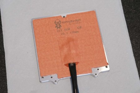
- Aluminum Bed - PrecisePrinterParts v0 Bed
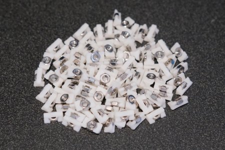
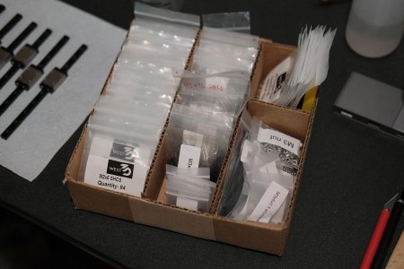
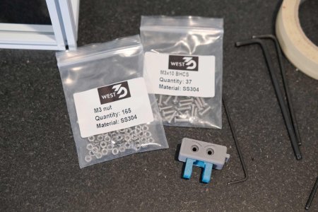
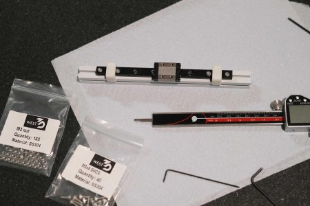
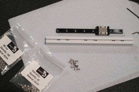
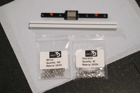
- Stainless Steel Fasteners - West3D BDF Fasteners Kit for Mcron
- Titanium Backers - DFH
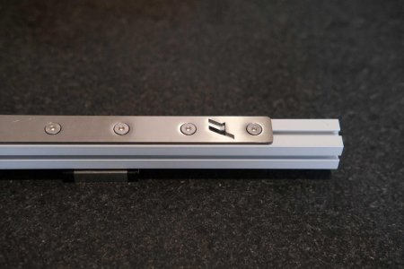
- Titanium Nut Bars - DFH
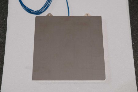
- Blue Manganese Flex Plate - DFH
Attachments
Last edited: