What's new
VORON Design

Register a free account today to become a member! Once signed in, you'll be able to participate on this site by adding your own topics and posts, as well as connect with other members!

Bondtech IDGA Set - 16.2mm?

majic79

Well-known member
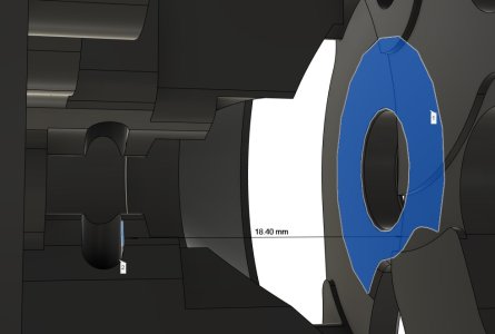
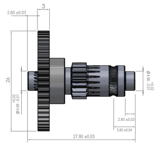
Hi All, I'm chasing some extruder issues on my new Trident build, and I thought I'd buy an original Bondtech gear set - IDGA seemed like a good way to eliminate any eccentricity in the drive. When I'm assembling CW2, it specifies 15.6mm offset from the drive gear to the centreline of the hobbed groove. Bondtech's drawing gives me 16.2mm (https://www.bondtech.se/product/oem-idga-set/), and it's enough that the Clockwork extruder doesn't snap together cleanly.

Is this even supported? Do I need to do something differently to get this to work? do I need to print a modified CW2 to get this working?
 
The 15.6mm figure in the manual is given as a starting point. From there you are expected to make further adjustments visually when assembling. The problem with this dimension is that the thickness of the gear is not the same on all parts. In the CAD file for the CW2 the gear is 4mm thick. However the drawing for the Bondtech gear calls out 3mm thickness. So you can see that this changes the reference point by +1mm. Now the crucial dimension is probaly from the other side of the gear where the bearing is because that's what determines the position of the gear within the CW2 housing.

A measurement of the CW2 step file gives a distance of 18.4mm from the iner face of the housing to the edge of the filament groove. The groove is 2.4mm across, so 1.2mm to its center.
18.4 +1.2 = 19.6mm.
If we examine the Bondtech drawing and do a little math this is precisely the same distance from the back of the gear to the center of the groove. So in theory it is correct but unfortunately that provides zero clearance and it would have to rub against the case if it were to perfectly center the drive groove over the filament groove. Depending on bearing thickness, this will also limit where the gear will locate.

So based on tolerances it seems like the Bondtech gear is not ideally dimensioned for the CW2. I would suggest measuring yours to see if it matches the drawing, looking at other gears, or modifying the CW2 motor plate model and re-printing to adapt it to the gear. Or maybe just live with it not exactly centered.
 

Attachments

  • CW2_gear_spacing.jpg
    CW2_gear_spacing.jpg
    71.1 KB · Views: 5
  • 15168_OEM_IDGA_Drawing.png
    15168_OEM_IDGA_Drawing.png
    28 KB · Views: 6
Last edited:
When I say that "things don't snap together cleanly" I mean there's aprox 0.5mm of seperation between the CW2 body and motor plate, probably caused by the 0 clearance at the gear. But it's a good point about "how closely does reality fit the theory" and it's not good news.

All I've got to hand is a vernier caliper and 25mm micrometer. Overall length is 27.96 (0.13mm out of spec). Long enough I can't fit it in my micrometer.

Back face of gear to shoulder (critical internal dimension) is 22.68mm which isn't far off the drawing specified 22.6 (+/- 0.03 at either end), but probably accounts for some of the negative clearance I'm seeing. Gear itself is 3.1mm on average, but that's not really an issue, there's clearance between the rear bearing and the gear, so it's not resting on the bearing, but it's being pushed into the motor plate.

The real question is what the dimension in the step file is between the motor plate surface and the shoulder for the bearing near the groove. When I get chance I'll take a look.

At least I can be a warning to some other poor soul looking at that and thinking "yeah, that'll fit - it says so on the Bondtech website" and the reality is that it doesn't even come close
 
Top