Pradit
Well-known member
Finally I have the parts which I self source ready.
And I have a place to keep my build log.
I will come and keep update here once I finish managing the photo.

This web help you make your mind for the color.
# Plan for my build:
1. 350 x 350 build
2. Octopus Pro 446 + TMC2209
3. Raspberry Pi 3B +
4. EBB36 Canbus
5. PITFT5
6. PI cam
7. Smoke detection alarm
8. Rapido
9. Octoprint
10. Klipper
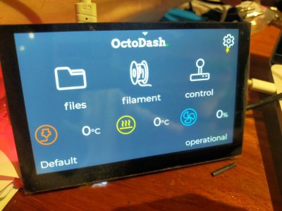
11. Octodash
12. Klicky
13. Filament runout Unklicky
14. PurgeBucket & Nozzle brush
15. Sensorless Homing
16. Sexbolt
17. Nevermore filter and more filter
18. Some sort of removable panel and door with magnets.
19. Rolling Voron
20. Boot from SSD drive
21. LED LED LED and LED
22. Umbilical cord
23. Relocation chain
24. More on fire hazard prevent and protection
25. Remote monitor
Since I source every part by myself so it's a waiting game.
Then I started to order PIF from @Stephan (discord username).
He kindly helps me find a way to deliver to me with a cheaper fee from Germany. Thanks for that.
# PIF

Here are the bags of the main printer part for Voron 2.4 R2 Rapido.

All the parts from the bag.

Accent color is orange.
1st bag base color.

2nd bag base color.

3rd bag base color.
Below here you can look at the print quality from PIF.


And I have a place to keep my build log.
I will come and keep update here once I finish managing the photo.
This web help you make your mind for the color.
# Plan for my build:
1. 350 x 350 build
2. Octopus Pro 446 + TMC2209
3. Raspberry Pi 3B +
4. EBB36 Canbus
5. PITFT5
6. PI cam
7. Smoke detection alarm
8. Rapido
9. Octoprint
10. Klipper
11. Octodash
12. Klicky
13. Filament runout Unklicky
14. PurgeBucket & Nozzle brush
15. Sensorless Homing
16. Sexbolt
17. Nevermore filter and more filter
18. Some sort of removable panel and door with magnets.
19. Rolling Voron
20. Boot from SSD drive
21. LED LED LED and LED
22. Umbilical cord
23. Relocation chain
24. More on fire hazard prevent and protection
25. Remote monitor
Since I source every part by myself so it's a waiting game.
Then I started to order PIF from @Stephan (discord username).
He kindly helps me find a way to deliver to me with a cheaper fee from Germany. Thanks for that.
# PIF
Here are the bags of the main printer part for Voron 2.4 R2 Rapido.
All the parts from the bag.
Accent color is orange.

1st bag base color.2nd bag base color.
3rd bag base color.
Below here you can look at the print quality from PIF.
Last edited: