VORON Design
You are using an out of date browser. It may not display this or other websites correctly.
You should upgrade or use an alternative browser.
You should upgrade or use an alternative browser.
My 1st 3d printer with 350 V 2.4 R2
- Thread starter Pradit
- Start date
Pradit
Well-known member
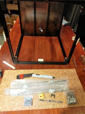
# Frame
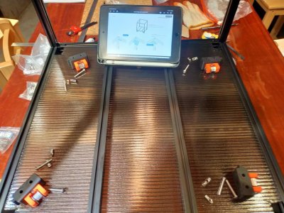
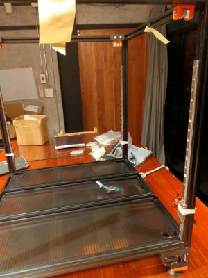
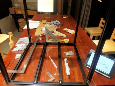
I don't know how hard would this be to square until I actually assemble it.
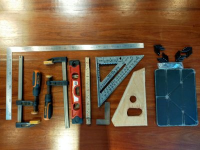
Flat glass is a must.
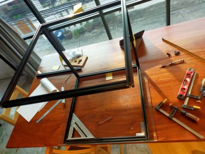
The lesson learned here is don't tighten them all yet.
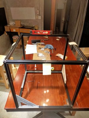
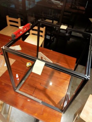
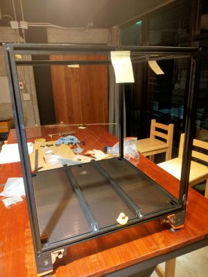
Finally as good as it gets to be a square cube.
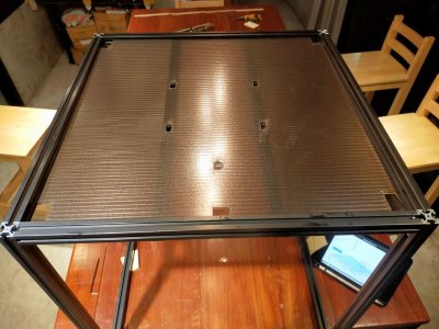
I don't have coroplast here in my local then I use polycarbonate roofs instead.
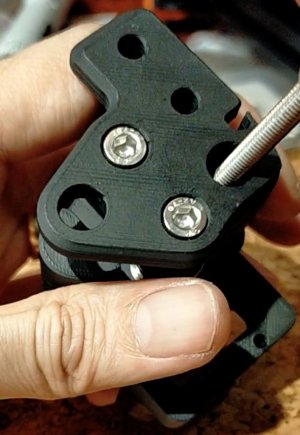
Try to align the nuts and holes.
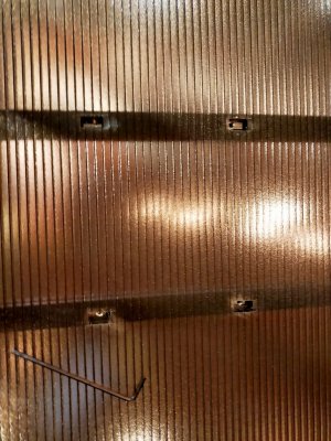
Obviously I have the wrong direction of the rail to the panel.
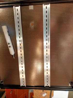
The din rail needs to be cut 2 pieces with the same hole alignment next time.
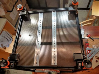
I don't know how hard would this be to square until I actually assemble it.

Flat glass is a must.

The lesson learned here is don't tighten them all yet.


Finally as good as it gets to be a square cube.

I don't have coroplast here in my local then I use polycarbonate roofs instead.

Try to align the nuts and holes.

Obviously I have the wrong direction of the rail to the panel.

The din rail needs to be cut 2 pieces with the same hole alignment next time.

Pradit
Well-known member
# Wiring
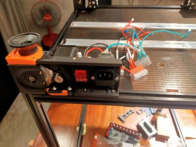
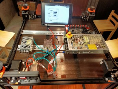
Completed wiring and tested voltage from each PSU. (24.1v and 5.01v)
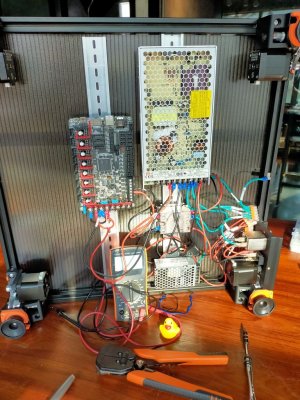
Removed all the jumpers and set all jumpers then added the TMC2209.
I'm going to use sensorless homing. I'm not sure yet which jumper needs to be set.
I'll deal with it later in the build.
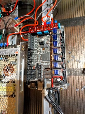
Zmotor wired from Z0, Z3, Z1, Z2.
Just look at the document twice for the location of each plug to make sure they are in
the correct position.
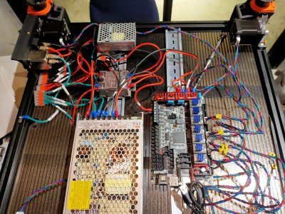
Completed wiring and tested voltage from each PSU. (24.1v and 5.01v)

Removed all the jumpers and set all jumpers then added the TMC2209.
I'm going to use sensorless homing. I'm not sure yet which jumper needs to be set.
I'll deal with it later in the build.

Zmotor wired from Z0, Z3, Z1, Z2.
Just look at the document twice for the location of each plug to make sure they are in
the correct position.

Pradit
Well-known member
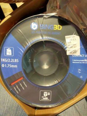
My 1st PLA filament arrived for testing.
# Linear Rail
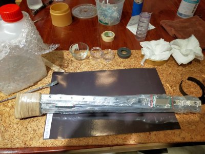
Let's strip and lube baby...
Sorting and testing the best one for XY and AB rail.
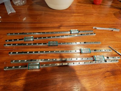
These are better than other so will be using them for XY and AB.
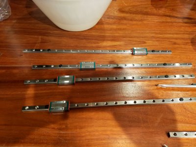
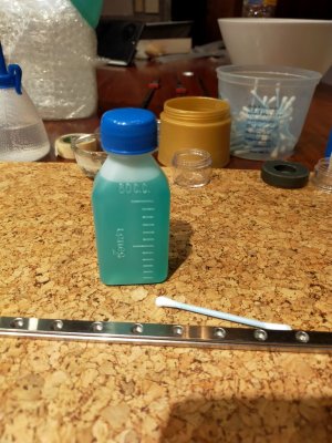
I was trying to blue my rail but failed.
The shop told me it doesn't work with coating shiny steel.
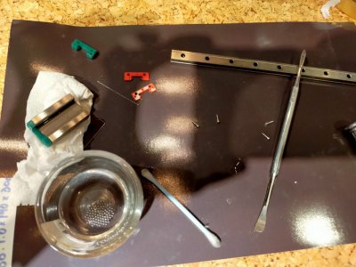
I prepared a magnet sheet laying around. It does help a lot when the ball jumps out accidentally.
Taking apart these rails really necessary? Can't we just lube them without taking them apart and clean first?
Man putting them back is a real pain in the B...
Clean them and under need the paper I had another big magnet to help holding.
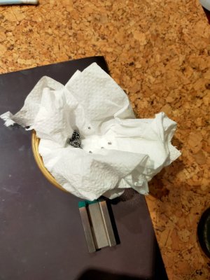
I sware I didn't loose any of the balls. It must came short right off the bag.
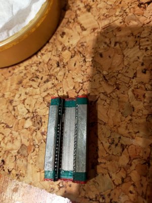
I've been asking this question and didn't get any answer so I tested it myself.
Can we use bike grease with the rail?
Answer is NO.
Hahaha .
.
I don't know coz of the grease is kinda sticky or coz I use magnets all over the place to hold them.
Then the balls get magnetized. The rail just didn't go smoothly as I expected.
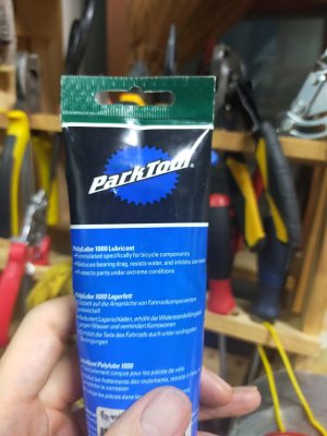
Don't try this at home...

# Linear Rail
Let's strip and lube baby...

Sorting and testing the best one for XY and AB rail.

These are better than other so will be using them for XY and AB.

I was trying to blue my rail but failed.
The shop told me it doesn't work with coating shiny steel.

I prepared a magnet sheet laying around. It does help a lot when the ball jumps out accidentally.
Taking apart these rails really necessary? Can't we just lube them without taking them apart and clean first?
Man putting them back is a real pain in the B...

Clean them and under need the paper I had another big magnet to help holding.

I sware I didn't loose any of the balls. It must came short right off the bag.

I've been asking this question and didn't get any answer so I tested it myself.
Can we use bike grease with the rail?
Answer is NO.
Hahaha
I don't know coz of the grease is kinda sticky or coz I use magnets all over the place to hold them.
Then the balls get magnetized. The rail just didn't go smoothly as I expected.

Don't try this at home...
Last edited:
Pradit
Well-known member
# Gantry AB Rail
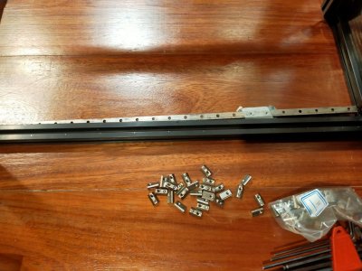
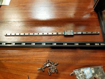
Repeat the same way I did with the Z rail.
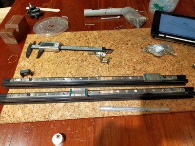
Check the manual 5M and 3M Tnut.
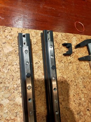
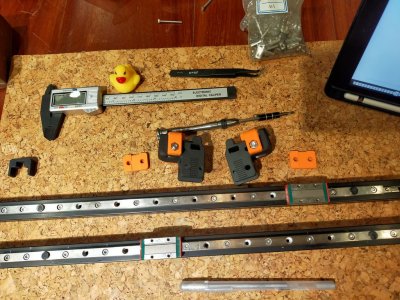
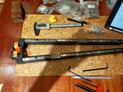
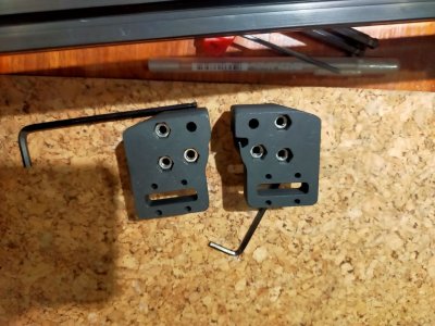
Double check the manual coz I was confused at first.
Mine has 1 part the hole just has no bevel or any groove m5 skew just goes through and falls off.
But I decide to use it anyway since it's only purpose to guide the bearing. Other bolts can hold.
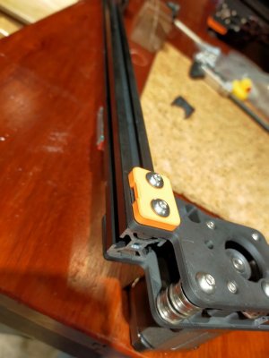
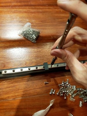
Gantry rail.
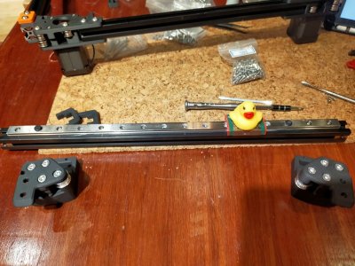
Just don't push too deep and don't tighten now.
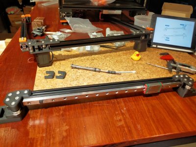
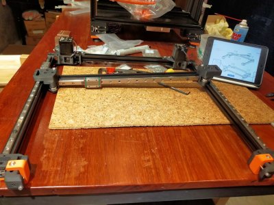
Gantry is ready to put into the frame.
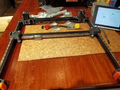
Repeat the same way I did with the Z rail.

Check the manual 5M and 3M Tnut.


Double check the manual coz I was confused at first.
Mine has 1 part the hole just has no bevel or any groove m5 skew just goes through and falls off.
But I decide to use it anyway since it's only purpose to guide the bearing. Other bolts can hold.


Gantry rail.

Just don't push too deep and don't tighten now.


Gantry is ready to put into the frame.

Pradit
Well-known member
# Gantry assemble
I put it sideway gravity help.
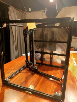
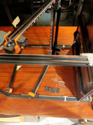
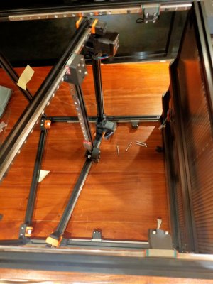
Gantry assemble done.
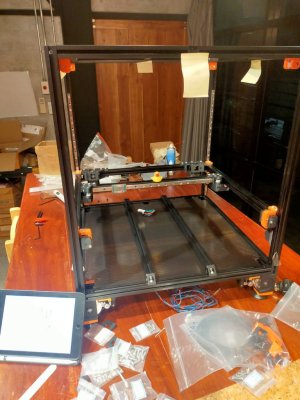
Z axis belt done.
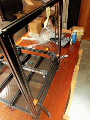
AB belt done but with some issue.
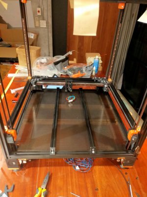
Gantry didn't move freely as it should and the discord user help suggested looking at the back.
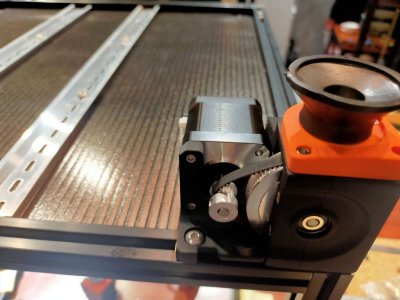
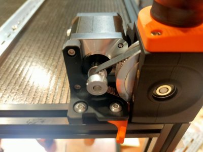
The belt went to the wrong hole on the B drive and on the A drive belt is over the idler.
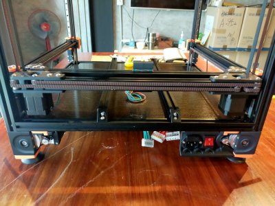
Follow this guide to de-racking the gantry.
Now it moves smoothly.
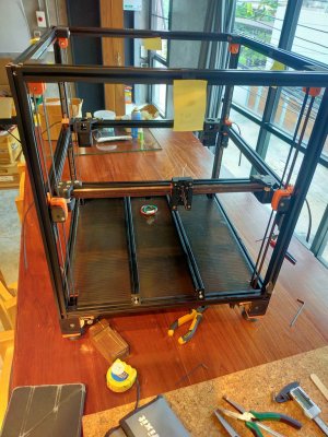
I put it sideway gravity help.


Gantry assemble done.

Z axis belt done.

AB belt done but with some issue.

Gantry didn't move freely as it should and the discord user help suggested looking at the back.
The belt went to the wrong hole on the B drive and on the A drive belt is over the idler.

Follow this guide to de-racking the gantry.
Now it moves smoothly.

Last edited:
Pradit
Well-known member
# Z cable chain
Since I'm planning for CANBUS umbilical cord so I only install Z cable chain.
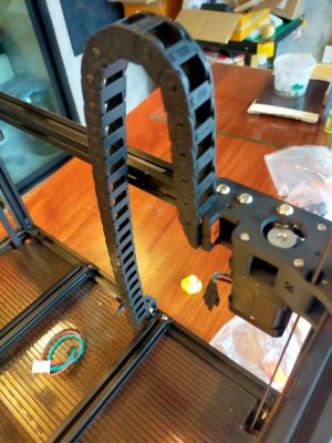
1st my mistake was to wire the B motor wire out just the mid of the chain.
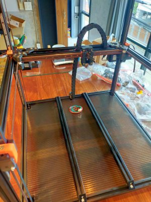
It supposes to go through the entire length of the chain and back to the motor.
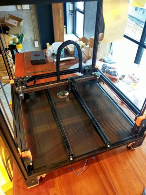
Then my B motor cable now has to find the shorter path to the board.
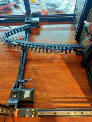
Since I'm planning for CANBUS umbilical cord so I only install Z cable chain.

1st my mistake was to wire the B motor wire out just the mid of the chain.

It supposes to go through the entire length of the chain and back to the motor.

Then my B motor cable now has to find the shorter path to the board.

Pradit
Well-known member
I went ahead setting up the CANBUS while waiting for a new crimping tool to arrive.
I follow the document guideline here: How to Use CAN Toolhead Boards Connected Directly to Octopus / Octopus Pro on CanBoot
If you need me to attach the pdf here please let me know.
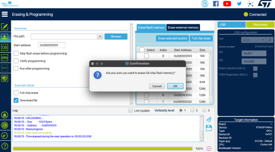
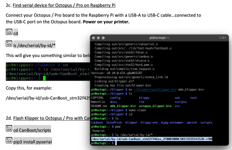
I follow the document guideline here: How to Use CAN Toolhead Boards Connected Directly to Octopus / Octopus Pro on CanBoot
If you need me to attach the pdf here please let me know.


Pradit
Well-known member
Ok a lot of things going on once I jumped into the CANBUS rabbit hole.
So after I finished put together the belt and gantry and hotend.
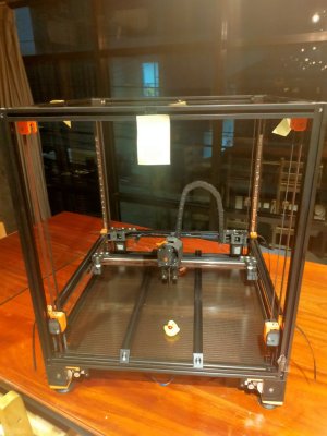
# CanBus
I started to set canboot and flash firmware for EBB36 as mentioned in the previous post.
Set the boot0 jumper on Octopus.
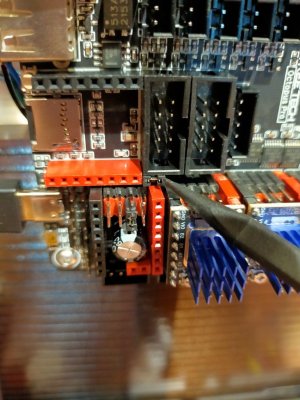
Octopus reset button is here. Don't do the same mistake as me press the one next to the SD slot.
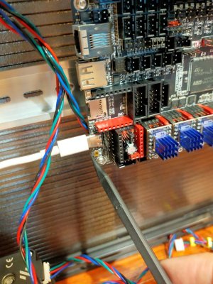
As follow the instruction I realized that the serial id will be able to query once in DFU mode.
After that it has to use UUID acquire from the conboot query.
Put jumper VBUS on EBB36.
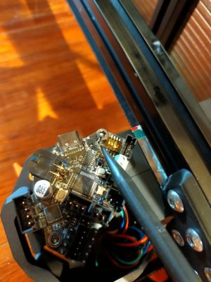
RJ11 and HI LOW wire.
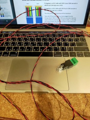
I used 22AWG for the HILOW wire.
So after I finished put together the belt and gantry and hotend.

# CanBus
I started to set canboot and flash firmware for EBB36 as mentioned in the previous post.
Set the boot0 jumper on Octopus.

Octopus reset button is here. Don't do the same mistake as me press the one next to the SD slot.

As follow the instruction I realized that the serial id will be able to query once in DFU mode.
After that it has to use UUID acquire from the conboot query.
Put jumper VBUS on EBB36.

RJ11 and HI LOW wire.

I used 22AWG for the HILOW wire.
Pradit
Well-known member
# Stealburner
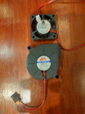
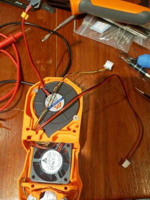
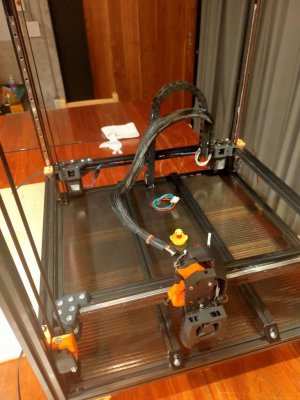
Installed HE fan.
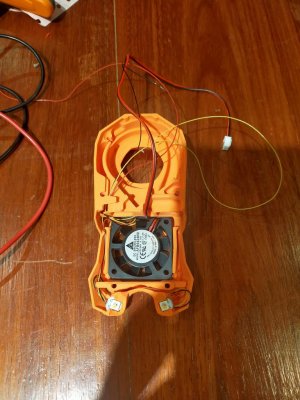
Taking apart of the part fan was labor intensive. There must be a better way to do this. Any comment?
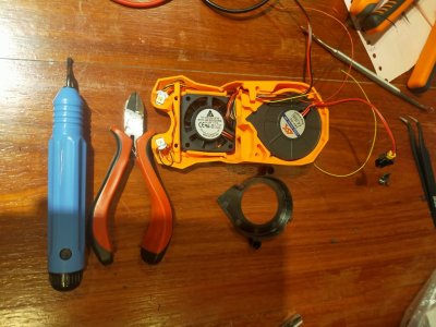
Checking LED wire length.
Crimped the LED wire to length.
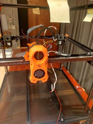
Test fit the umbilical cord with sleeve.
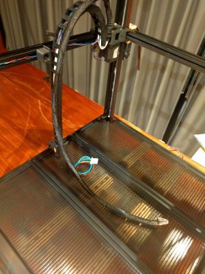
With this test fit I managed to have EBB success as explained below.
However, after I have the LED on successfully then I decided to plug all the motors to the board.
After that EBB was unable to turn on.
Till I found 1 of the crimp was loose.
Due to I used 16AWG for my V+ V- wire and it was no way to crimp perfectly into the connector so small.
So I started the Aviation connector journey. (See the next post.)
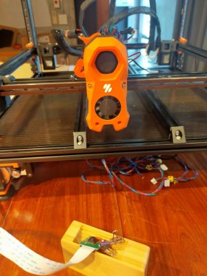
Power on EBB36 and everything work no smoke.
Extruder motor move, fan move.
In order to have my CANBUS to work I learned that comment out the serial config and use UUID instead in cfg.
Then it needs to reference the new pin from the EBB board with the prefix you put in the [mcu xxx]
In this case, the new pin is PA1 and I use the alias as FAN1.
I have to put "can0" prefix for that pin to work.
However, the LED didn't turn on.
With the help from discord friend.
The LED config in cfg file has to be:
Installed HE fan.

Taking apart of the part fan was labor intensive. There must be a better way to do this. Any comment?

Checking LED wire length.

Crimped the LED wire to length.

Test fit the umbilical cord with sleeve.

With this test fit I managed to have EBB success as explained below.
However, after I have the LED on successfully then I decided to plug all the motors to the board.
After that EBB was unable to turn on.
Till I found 1 of the crimp was loose.
Due to I used 16AWG for my V+ V- wire and it was no way to crimp perfectly into the connector so small.
So I started the Aviation connector journey. (See the next post.)

Power on EBB36 and everything work no smoke.
Extruder motor move, fan move.
In order to have my CANBUS to work I learned that comment out the serial config and use UUID instead in cfg.
Ruby:
[mcu]
##  Obtain definition by "ls -l /dev/serial/by-id/" then unplug to verify
##--------------------------------------------------------------------
#serial: /dev/serial/by-id/usb-CanBoot_stm32f446xx_2F0003000C50315939343520-if00
#restart_method: command
#baud: 500000
##--------------------------------------------------------------------
canbus_uuid: b96112656a28


[mcu can0]
canbus_uuid: 31401ccdca9b
Then it needs to reference the new pin from the EBB board with the prefix you put in the [mcu xxx]
Ruby:
aliases_fans:
    FAN0=PA0,FAN1=PA1
.....

## HOT END FAN
[heater_fan hotend_fan]
##  Hotend Fan - FAN1
pin: can0:FAN1
max_power: 1.0
kick_start_time: 0.5
heater: extruder
heater_temp: 50.0
In this case, the new pin is PA1 and I use the alias as FAN1.
I have to put "can0" prefix for that pin to work.
However, the LED didn't turn on.
With the help from discord friend.
The LED config in cfg file has to be:
Ruby:
## RGB
[neopixel StealthBurner]
pin: can0:RGBLED
chain_count: 3
color_order: GRBW #GRB
initial_RED: 0.0
initial_GREEN: 0.0
initial_BLUE: 0.0
initial_WHITE: 0.3
Last edited:
Pradit
Well-known member
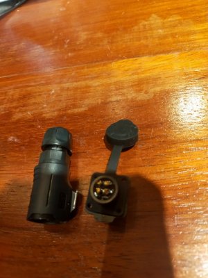
# Aviation connector
1st of all, I have no idea what I was doing to be honest.
You guys can comment me so I could fix it or do better next time.
I soldered the wire to one end of the female aviation plug.
Then crimp them really painfully.
Soldering and crimping are not my strong suit.
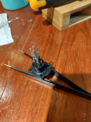
Aligning orientation.
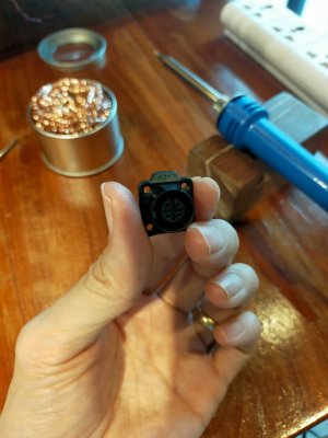
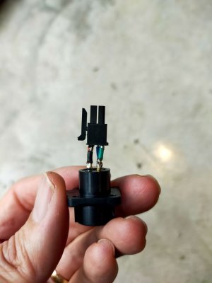
More soldering the wire to another end of the connector.
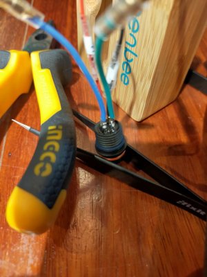
Figure out the way to put my 16 AWG V+ V- wire into the sleeve and to the connector.
I decided to use 20 AWG soldered to the connector and use more connector between them.
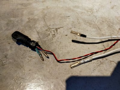
Put sleeve on.
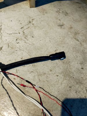
After I plug it in now the power EBB36 went back on. LED off... dang...
I tried to query it but return error.
Took me sometime then someone from discord suggested using a multimeter check.
I did check the continuity of the wire every step of the way when I assemble the cord.
But when it plugged into the EBB36 I don't know how to check.
I went to check it again anyway on the board behind the canbus port has 2 metal parts for Hi and Lo.
There I found my Lo pin was not deep enough.
Fixed it.
Now everything back, LED on, Fan on and no smoke.
But...
I still don't know what happen with the query it return nothing.
And what is "Error-Active" :
1st of all, I have no idea what I was doing to be honest.
You guys can comment me so I could fix it or do better next time.
I soldered the wire to one end of the female aviation plug.
Then crimp them really painfully.
Soldering and crimping are not my strong suit.

Aligning orientation.


More soldering the wire to another end of the connector.

Figure out the way to put my 16 AWG V+ V- wire into the sleeve and to the connector.
I decided to use 20 AWG soldered to the connector and use more connector between them.

Put sleeve on.

After I plug it in now the power EBB36 went back on. LED off... dang...
I tried to query it but return error.
Bash:
~/Canboot/scripts $ python3 flash_can.py -i can0 -q
Resetting all bootloader node IDs... Checking for canboot nodes...
ERROR:root:Can Flash Error Traceback (most recent call last):
File "flash_can.py", line 602, in main    loop.run_until_complete(sock.run_query(intf))
File "/usr/lib/python3.7/asyncio/base_events.py", line 584, in run_until_complete
return future.result()  File "flash_can.py", line 488, in run_query
await self._query_uuids()  File "flash_can.py", line 406, in _query_uuids
resp = await self.admin_node.readexactly(8, diff)
File "flash_can.py", line 282, in readexactly
return await asyncio.wait_for(self._reader.readexactly(n), timeout)
File "/usr/lib/python3.7/asyncio/tasks.py", line 416, in wait_for
return fut.result()  File "/usr/lib/python3.7/asyncio/streams.py", line 677, in readexactly    raise IncompleteReadError(incomplete, n) asyncio.streams.IncompleteReadError: 0 bytes read on a total of 8 expected bytes
Took me sometime then someone from discord suggested using a multimeter check.
I did check the continuity of the wire every step of the way when I assemble the cord.
But when it plugged into the EBB36 I don't know how to check.
I went to check it again anyway on the board behind the canbus port has 2 metal parts for Hi and Lo.
There I found my Lo pin was not deep enough.
Fixed it.
Now everything back, LED on, Fan on and no smoke.
But...
I still don't know what happen with the query it return nothing.
Bash:
pi@octopi:/tmp $ cd
pi@octopi:~ $ cd Canboot/scripts/
pi@octopi:~/Canboot/scripts $ python3 flash_can.py -i can0 -q
Resetting all bootloader node IDs...
Checking for canboot nodes...
Query Complete
And what is "Error-Active" :
Bash:
pi@octopi:~ $ ip -detail -statistic link show can0
3: can0: <NOARP,UP,LOWER_UP,ECHO> mtu 16 qdisc pfifo_fast state UP mode DEFAULT group default qlen 1024
    link/can  promiscuity 0 minmtu 0 maxmtu 0
    can state ERROR-ACTIVE restart-ms 0
      bitrate 500000 sample-point 0.875
      tq 125 prop-seg 6 phase-seg1 7 phase-seg2 2 sjw 1
      gs_usb: tseg1 1..16 tseg2 1..8 sjw 1..4 brp 1..1024 brp-inc 1
      clock 48000000
      re-started bus-errors arbit-lost error-warn error-pass bus-off
      0          0          0          0          0          0         numtxqueues 1 numrxqueues 1 gso_max_size 65536 gso_max_segs 65535
    RX: bytes  packets  errors  dropped overrun mcast
    121119     16515    0       210     0       0
    TX: bytes  packets  errors  dropped carrier collsns
    7390       1300     0       0       0       0
Last edited:
Pradit
Well-known member
Whew, back from a lot of tinkering and digging.
And now the CANBUS officially on.
I had many issues encounter along the way.
And with helps both discord and teamfdm.com.
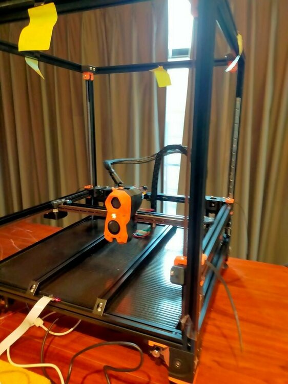
# Hotend temp reading wrong.
1st my hotend temp was 48c and bed temp was 25c.
I thought it just config the sensor type to 104nt-4 should be enough.
But with @michaelmacintyre help I found that printer.cfg I had came with Revo default.
I had to remove
pullup_resistor
Now it's work.
Also the thermistor that came with Rapido has mulex microfit which I couldn't find in my local.
@smirk suggested me to cut it and use the connector I have. So I did it.
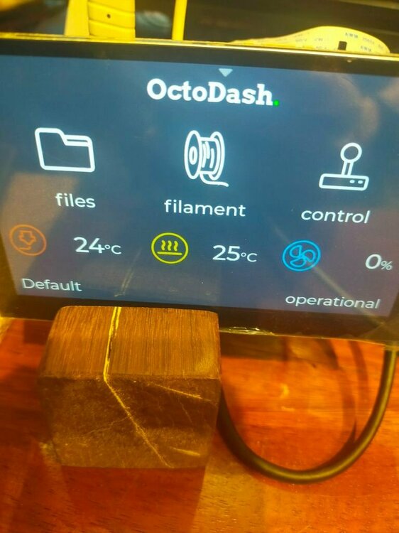
# Octoprint lagging
Then I had my octoprint not very responsive. Any gcode command I sent
it took like 5 sec to respond. Boot time is 5 mins.
So I decided to deactivated all plugins.
Octoprint boot time within 1-2mins and gcode command respond within 1 sec.
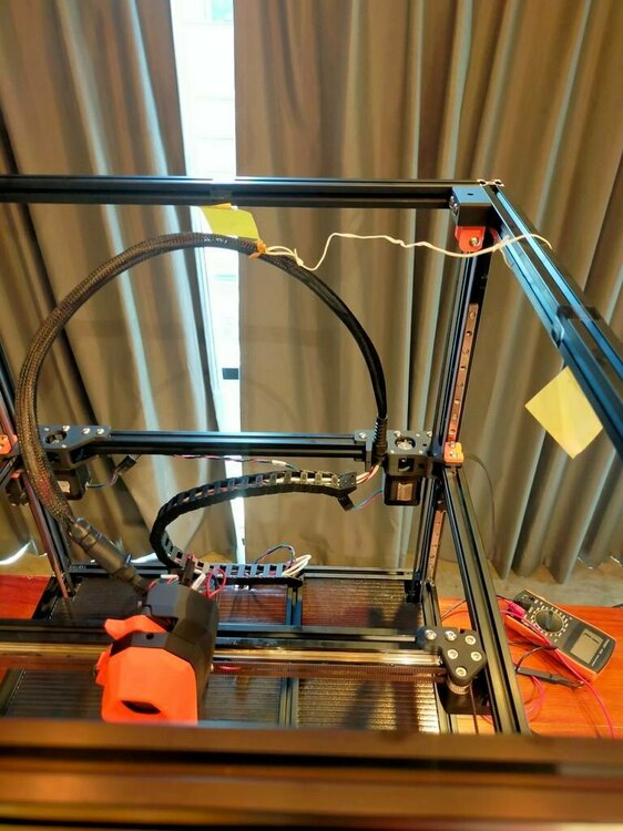
This just temporary hot fix for my chain which blocking when Y homing.
Once I could print I'll print the proper Z chain relocation.
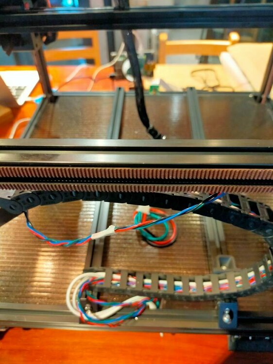
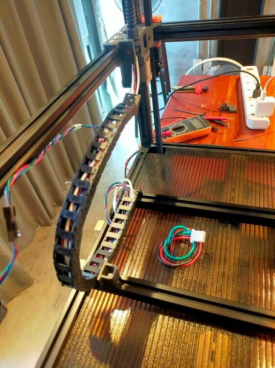
*But the chain is still too big so I changed to smaller one last night.
I also need to print the proper canbus holder for my wire relief.
# Klipper disconnect randomly
I got klipper shutdown, disconnect, "serial is dead", randomly.
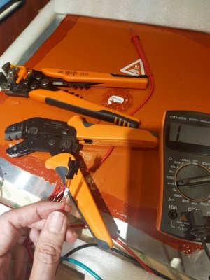
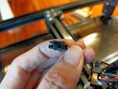
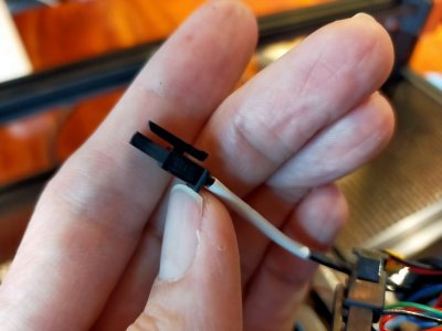
So I checked continuity all the time. But somehow my CANBUS connection has a bad crimp.
1 of the pin wasn't go deep enough.
Sad but I had to re-crimp. :~(
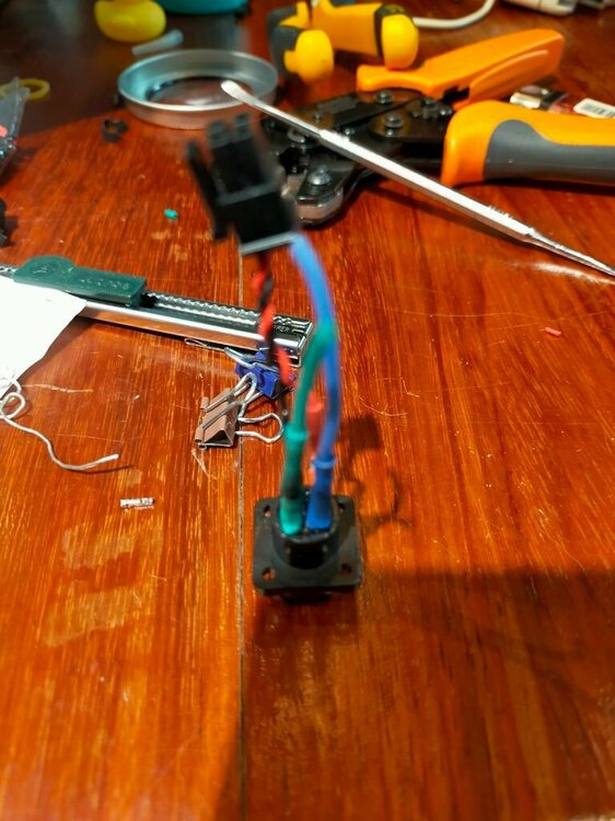
*Image is blur you can tell how mad I am...

And now the CANBUS officially on.
I had many issues encounter along the way.
And with helps both discord and teamfdm.com.

# Hotend temp reading wrong.
1st my hotend temp was 48c and bed temp was 25c.
I thought it just config the sensor type to 104nt-4 should be enough.
But with @michaelmacintyre help I found that printer.cfg I had came with Revo default.
I had to remove
pullup_resistor
Now it's work.
Also the thermistor that came with Rapido has mulex microfit which I couldn't find in my local.
@smirk suggested me to cut it and use the connector I have. So I did it.

# Octoprint lagging
Then I had my octoprint not very responsive. Any gcode command I sent
it took like 5 sec to respond. Boot time is 5 mins.
So I decided to deactivated all plugins.
Octoprint boot time within 1-2mins and gcode command respond within 1 sec.
This just temporary hot fix for my chain which blocking when Y homing.
Once I could print I'll print the proper Z chain relocation.


*But the chain is still too big so I changed to smaller one last night.
I also need to print the proper canbus holder for my wire relief.

# Klipper disconnect randomly
I got klipper shutdown, disconnect, "serial is dead", randomly.
So I checked continuity all the time. But somehow my CANBUS connection has a bad crimp.
1 of the pin wasn't go deep enough.
Sad but I had to re-crimp. :~(

*Image is blur you can tell how mad I am...

Last edited:


