What's new
VORON Design

Register a free account today to become a member! Once signed in, you'll be able to participate on this site by adding your own topics and posts, as well as connect with other members!

Tronxy x5sa -> Franken Voron Build

PHOTO-2023-11-24-09-06-57.jpgPHOTO-2023-11-24-09-06-58 2.jpgPHOTO-2023-11-24-09-06-58.jpg

This is a bit of an unholy hybrid of a few things
1. SB's CW2 extruder
2. The Mellow SB2040 split toolhead CANBUS PCB
3. The 5015 Fan Mod for the AB (https://github.com/Greg191134/Voron/tree/master/Afterburner Optimisation/5015 fan mod)

I used the 5015 mod well for two reasons, extra airflow (and parity with the SB part cooling fan) .. but also its shape is larger, it fits more neatly on top of the SB extruder.
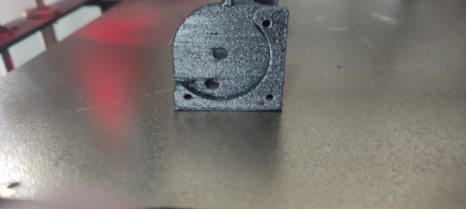
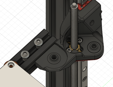
I modded the back piece of this mod to basically hollow it out to add space to fit the split PCB and sink the screws holding the front half deeper for the same reason. I also added some pins to the PCB (had to source thinner ones than the standard ones) to be able to disconnect the fans easily, especially the bottom one, since AB kind of relies on this idea.
I suppose I could go through a few more revisions there and move the screws from the back to the front, it just didn't really seem worth it, given that for the bottom right pcb screw I still would be stuck with ~3mm of space ..
Although now that I write this .. I do have some M2 heat inserts from another project .. those are only 3mm deep .. I forget if I have 2mm or 3mm to work with there .. if its 3 .. it would be way more secure with those smaller screws, but into a heat insert .. and then it may be worth moving the front mounting screws to the front .. to make a bit more horizontal room to fit the insert on the top left side .. dunno .. it works for now .. I can play with in in CAN when the printer is built ..
I feel like out of this project I really should spin out a pile of "little" mods .. kind of separate from this conversion as a whole .. there may be use for them existing a bit more separately ..
The only thing that was particularly annoying about this is that it ended up with a massive overhang (the whole hollow is an overhang) .. so that doesn't look pretty .. but its on the inside .. so who cares ;)
Also the tolerances there are super tight .. the holes for mounting the PCB are super tight and shallow .. One is right beside one of the front holding screws, and literally only has about 3/4 of its diameter actually has plastic, the rest of the screw head opening for the other screw .. the other screw has a full diameter, but its super shallow, since it backs onto the back of the fan housing, so there is literally 3mm to work with there.
I had some M3x3 and M3x4 screws I ended up using there .. it definitely doesn't feel super safe to try remove that PCB more than a couple of times before those holes would probably get stripped.
Ignore the sticking out wires on the first image, I'm not done shortening/crimping all the toolhead things ;)

Another side note ..
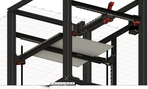
I could not come up with a good way to run an X chain .. because of the inverted XY mechanism, there wasn't clearence for the chain loop to properly clear when the toolhead was on max chain extension .. so this build is an umbilical hybrid ..
I still kept a Y chain, it only has the XY endstop cable in it. And the CANBUS wire is going to be pinned to the bowden tube.
I ended up with two custom bits of fittings ..
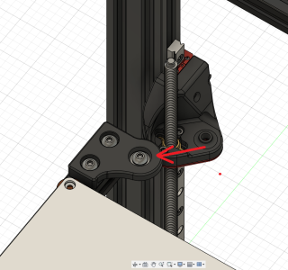
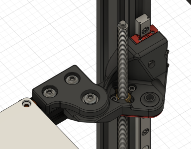
1. a custom mount for the relief sleeve thing on the back of the CW2 .. its also a bit extra weird because of he inverted nature of the whole setup, the spot where the magnet for the X endstop had to move from the X rail mount itself, to the little arm on the back of the CW2 (which was very convenient, this is a super easy piece to swap out and iterate on, I'd hate to have to swap out the stuff holding the belt in place and have to re-square the XY and re-tension the belts each time :). This is based on some other umbilical adaptors I've seen, really its just replacing the chain holes with a giant taped M14 (if I recall correctly) hole to attach the relief sleeve.
2. a custom little cube that fits another one of those relief sleeves on the back of the printer .. I figured why not, let's give that a bit of spring as well ..


PHOTO-2023-11-24-09-53-32.jpgPHOTO-2023-11-24-09-53-33.jpg

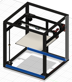
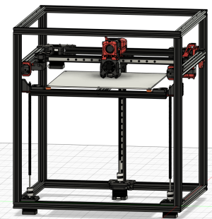
Oh yea .. some notes on build volume ..

Z is looking like I may be able to get about 300mm
X I can just go outside the build plate on either side .. so a full 330mm
Y is not too bad either .. losing ~25mm at the front, and ~5mm on the back .. so still a solid 300mm

So all in all, considering that Voron puts all the components INSIDE the frame .. (Tronxy had pulleys and whatnot on the TOP of the frame, on the CORNERS, so that would have saved a lot of space) .. getting 300x330x300 doesn't seem that bad ;)

---

I look forward to converting this further into a Trident .. right now its almost a working 1.8 style printer :)

With Trident I can un-invert the XY drive and basically use stock Trident parts there .. the Y chain can switch to being normal Trident style as well.
Given that at its lowest point the bed surface is ~60mm from the deck .. the Trident Z setup should actually be much more compact there and probably get me another 30mm of Z volume maybe ..
I don't think there is much I can do about the X or Y volumes .. unless I can hack the tensioners somehow to be smaller .. they eat ~30mm into the Y .. but this frame uses a 4020 extrusion there .. perhaps if I can mount the tensioner agains that somehow .. it just feels like it'd be harder to make sure its actually square with the axis .. so maybe not .. but there is a lot of potential room on the back .. so perhaps if I can change how the AB mounts work .. I can pretty safely chop out at least 15mm there .. so maybe .. maybe with some more modding I can actualy get back the full 330x330 build volume ..

But first .. get it to fully work .. try to reclaim scraps of build volume later :)
 
Wow I'm happy to hear you're doing this. On monday I bought a cheap tronxy x5sa for the frame thinking I'd do either like you a trident(maybe 2.4), or VZbot! I'd be very interested in any files you're willing to share. Currently I think the easiest thing for me is going to end up be doing a VZbot XY, trident Z for the Z-tilting
 
Ok I'm pretty happy with this setup .. I was able to get the XY motors running 1.2amps without overheating ;) .. allowing for much higher acceleration .. it looks a bit freakish having it do such abrupt acceleration movements ;)

I got a voron cube printed pretty much perfectly .. there is some weird banding on the back X face .. the other faces look perfect .. not sure what may causing that .. ideas ?

X: X.jpeg
Y: Y.jpeg
Y Back: YB.jpeg
X Back: XB.jpeg

I still need to fully enclose it for ABS prints .. I still need to do up the exhaust system .. there is still some weird "click" on what seems in the Right XY motor .. I'll have to take apart the XY belts and check the motors .. but this is very close to done ..

Progress so far:
Overall Pic.jpeg

I do want to replace the motors eventually with proper LDO's or something .. and I do want to get proper Z screw motors .. (I'll get 3 when I do so I can work towards the Trident conversion) .. but overall I'm quite happy with how its turning out ..

I'm waiting for some new bowden tubing .. it turns out when I bought some clear tubing a while ago .. it was wrong inner diameter .. so its a bit tight ..

One of the next things I want to start working towards is printing an ERCF system and playing with that :) so yea I'll need a bunch of tubing there :)
 
Hmm .. so I just replaced the tr black sensor with a proper omron inductive sensor .. so much more reliable .. I can rely on the z offset now :) .. getting very close to done now .. I also turned off stealth chop ..

the stock motors are not super quiet without stealth chop .. but I was directed to https://github.com/andrewmcgr/klipper_tmc_autotune .. I’ll have to try to measure the parameters on the stock steppers .. but it might allow tuning the drivers to some kind of more quiet mode ..

Finally it feels like it’s getting ready to be “done” .. last attempt at printing with the stock trident profile on orca slicer went very well, had to worry about the minimum layer time slowdown :) .. and it didn’t sound like the xy is being super loud ..
 
Happy new year!! 🎆


Love this project, finally I've found a project that uses stock parts... Thanks very much!

For now I'm going printing all parts, buy extrusions and others parts needed, and waiting from China(live in Brazil, 6x more expensive, and a month to delivery) can give me time to learn how to do this without errors, have only my X5SA Pro to do all before disassembly and mod. My mods are Klipper with Klipperscreen, SB toolhead with Volcano and Galileo, and using PEI sheet.

Can I print parts in PETG? ABS without enclouser is widly challenge!
 
Last edited:
Happy new year!! 🎆


Love this project, finally I've found a project that uses stock parts... Thanks very much!

For now I'm going printing all parts, buy extrusions and others parts needed, and waiting from China(live in Brazil, 6x more expensive, and a month to delivery) can give me time to learn how to do this without errors, have only my X5SA Pro to do all before disassembly and mod. My mods are Klipper with Klipperscreen, SB toolhead with Volcano and Galileo, and using PEI sheet.

Can I print parts in PETG? ABS without enclouser is widly challenge!
This is a Voron build, so you really want the parts in ABS/ASA otherwise you risk having them wrap.

I had to pick up some extra parts, some linear rails, a few extrusions, linear bearings. And lots of hardware (screws, tnuts, etc).

The VZbot XY system may have been an interesting choice to use here as well .. it would allow retaining more of the Z height .. but also would require some creative CAD modding to make this more voron .. so I'm pretty happy where I ended up)

At this point I'm pretty happy with where I've ended up .. I will still take the time to continue building out that repo with the STLs and instructions .. I'm at the final tuning phase with the printer myself ..

At this point this is effectively a V1.8 + Umbilical + CAN + Trident style Skirts with all the electronics below. (Oh and a hacky Stealthburner / Afterburner hybrid .. because I wanted extra flexibility with the toolhead .. I want to (eventually) play with longer hotends and didn't like how you have to effectively make a whole separate size modded stealthburner for the longer cooling ducts .. I may still build one eventually, but for now the simpler cooling system from the AB works well enough. (And I'm using the modded 5015 part cooling fan version, so its roughly equivalent in cooling power)

I will still continue a phase two of this which will Turn this into a Trident. Basically replacing the whole Z system. I have some early CAD ideas on how the bed mounting system could work, but it needs testing and fitting .. not in a hurry to do this .. I'm very happy with the setup so far .. I'm getting amazing first layers by just throwing away the bed springs and replacing them with simple standoffs .. the klipper bed mesh is taking care of adjusting for the front/back tilt, the the klipper z_tilt system is taking care of the left/right tilt (so the Z steppers are synced ideally).

If you have not yet, I recommend you upgrade your glass build surface to a PEI sheet .. the tronxy ones for the 330 beds are annoyingly expensive, but they seem to do a better job and its much easier to get stuff off them. And then upgrade your bed probe from the TR sensor to a voron spec omron sensor .. or a clicky or something (if you're still using the stock tronxy motion system, you should have a bunch of spare room around the edges to mount a clicky dock I think) .. for that consistent probing .. the TR sensor on mine was a bit hit and miss .. my omron sensor now is perfect, once I set my z offset I've not needed to touch it since ..

And I will probably do a part 3 which replaces the old heated bed with the AC heater based one the stock Trident design.

---

WhatsApp Image 2024-01-04 at 18.25.45_193da3f0.jpg

I'm really happy with my first layers:
WhatsApp Image 2024-01-04 at 18.47.41_4a2e2f73.jpg
 
Yeah, I'm using PEI Sheet(mentioned above haha)... That TR Sensor was first to see trash, just before Chitu Board... This is my first printer, started with a pile of shit, now expend all money again to get a decent one. Lessons and experiences...

Bought all BOM to convert directly to Trident... Except Bed Kit, is too expensive here, and import from China are impossible due 92% fee tax over U$50 itens... It's a dream upgrade. To buy MGN's I need buy one by one to evade overpriced tax.

Printing parts in ABS with low speed, and draft shield, until now having a litle warp, trying improve brim/shield to get best results, and ugly because it's a Tronxy. hahaha
 

Attachments

  • IMG_20240105_165557.jpg
    IMG_20240105_165557.jpg
    219.5 KB · Views: 10
Last edited:
Yeah, I'm using PEI Sheet(mentioned above haha)... That TR Sensor was first to see trash, just before Chitu Board... This is my first printer, started with a pile of shit, now expend all money again to get a decent one. Lessons and experiences...

Bought all BOM to convert directly to Trident... Except Bed Kit, is too expensive here, and import from China are impossible due 92% fee tax over U$50 itens... It's a dream upgrade. To buy MGN's I need buy one by one to evade overpriced tax.

Printing parts in ABS with low speed, and draft shield, until now having a litle warp, trying improve brim/shield to get best results, and ugly because it's a Tronxy. hahaha
For the skirts .. quality really doesn't matter .. as long as it doesn't fall apart .. for your XY you want it a little bit more sturdy ..

Did you end up also sourcing a whole new frame or are you converting your tronxy to a trident?

If so .. You're ending up with a bunch of 2040 extrusions where the BOM calls for 2020's .. so you will need a few modified parts for the XY setup (I had to create those for my mod) .. but since I went to V1.8 .. I ended up having to Mirror the XY setup basically on every piece .. to flip it to allow for the Z linear rods below the extrusion. If you're going directly to Trident you don't need to invert them .. but you do need the modified versions of the back A/B drive mounts to fit over the 2040 extrusions.
For draft shielding .. you could just do some very ugly CARDBOARD thing around your frame .. whatever you need to do to just make it into a clean closed space .. assuming the standard tronxy setup .. just give it enough room for the bed to move .. and for the hotend on top to move .. but otherwise that will be much better than nothing (or a printer draft shield).
 
For draft shielding .. you could just do some very ugly CARDBOARD thing around your frame .. whatever you need to do to just make it into a clean closed space .. assuming the standard tronxy setup .. just give it enough room for the bed to move .. and for the hotend on top to move .. but otherwise that will be much better than nothing (or a printer draft shield).
I'm using a cardboard(tronxy box) and draft shield in prints... All 4 foots skirts are like photo, little warp in corners, with 10 or 20mm brim, warp piece in corners but not in brim(probably because density), now waiting more ABS arrive to continue prints.

Will stay with 4020 in stock position, and add 2 more 490mm in bottom front/rear, to stand Z Axis and Z motors...
 

Attachments

  • v12.png
    v12.png
    304.2 KB · Views: 10
Last edited:
Oh that's a nice approach .. you shift the whole back and front by 20mm .. but then you can use stock parts .. nice :) and its not like you get any less print volume than by build either .. I like it :) If I had the extra extrusions I may go this way too :) .. maybe I will order those two extra extrusions when I order the extrusions for the bed frame

did you solve how you're going to mount your bed?
 
Screenshot 2024-01-06 174521.jpg
This is my current prototype idea for how the original bed could be mounted (first draft really, I was mostly fitting things together to understand how long extrusions I may need to order for under the bed) .. I'm hoping that those ABS pieces mounted to the bed extrusions are sturdy enough .. they should be .. if not I can model them thicker .. I'll be months before I actually start working on the actual trident conversion, I'd be happy to work with you so we can combine our ideas.

I'm not too worried about the front pieces, but the back pieces I do still need to work on to come up with a way to have that be very sturdy
 
I like your idea with the extra 490mm extrusions I will most likely use it when the time comes to do my Trident conversion :) May as well be able to use stock models right?
 
I like your idea with the extra 490mm extrusions I will most likely use it when the time comes to do my Trident conversion :) May as well be able to use stock models right?
Right!

Your ideia to hold bed in front are better than mine... I don't have skills to mod complex pieces in Fusion, so sad... :cry:
 

Attachments

  • Bed Mod.png
    Bed Mod.png
    291 KB · Views: 6
  • v12.png
    v12.png
    908.2 KB · Views: 5
I've acquired some skills in meanwhile... Need finishing bottom but ideia is realized
 

Attachments

  • bem_mod1.png
    bem_mod1.png
    274.8 KB · Views: 6
  • bed_mod.png
    bed_mod.png
    262.4 KB · Views: 4
I've acquired some skills in meanwhile... Need finishing bottom but ideia is realized
I purposely pushed the bed to the front to maximize the print volume, otherwise you lose a lot of volume on the Y axis ..

Do you need a hand modelling anything? I’d be happy to help :) not like I’m amazing at it, but I’ve managed to teach myself enough fusion to makes do :)

I remembered why I won’t use your extra extrusion idea .. it will cost me replacing my X rails .. but I want to see if I can redesign how both the idlers and the motor mounts fit so I can actually gain an extra 20mm at the front and back of print volume :)
 
There, I finally got around to trying to make the more compact, 2040 compatible idler design.

I still have to modify the other idler the same way .. but this seems like it should do the trick ..

I removed one of the mounting screws from the horizontal extrusion, but I added back a smaller M3 screw holding it from the side to the 2040, with what feels minimal sacrifice to the rigidity of the original design. (ignore that the red part is overlapping, fusion gets very confused when you add too many joints :) )

Screenshot 2024-01-07 152356.png

This now gives me an additional 16mm of forward gantry movement .. (Like I said .. I'll need to get new Y rails when it comes to to actually use this .. but I should be able to use probably 100% of my bed at that point)

This means that in the final Trident design I'll need to make the bed mounts ~16mm longer .. not a problem :)

Screenshot 2024-01-07 152748.png

On X I'm getting 328 .. there is not much room to try to improve anything there ..
But on Y I'm down to ~300 .. this gives me back another 16 .. so 316 .. and if I'm lucky I can get another 16 when I re-work the back motor mounts .. so that would give me all 330 ..

still no "spare" room to try to mount any kind of nozzle scrubbing .. or something like a klicky probe .. heck .. there isn't even enough room to mount the Z endstop .. but at least I'd get the whole print volume :)
 
Did a bit more work to convert the back mounts to give a bit of extra room, then shifted things a bit more to see how much room I could squeeze out of the back .. and it looks not bad .. I think I could actually fit the Z limit switch in there.

Screenshot 2024-01-07 185919.png
 
I think I've finished my CAD modifications, has much time to adjusts aesthetics, about a month because logistics here are awfull(China to Brazil 5 days, Post Office to my home 20~25 days)...

I've uploaded project to get feedbacks, don't know if was support is necessary in bed rear, but stock are so tiny I'm thinking need it. Staying touching nozzle on bed to feelings better hahahaa :LOL:


1704715514373.pngI love this, good ideia!
 

Attachments

  • mod.png
    mod.png
    226.7 KB · Views: 5
Top