VORON Design
You are using an out of date browser. It may not display this or other websites correctly.
You should upgrade or use an alternative browser.
You should upgrade or use an alternative browser.
Voron 2.4r2 350 build
- Thread starter Coyote
- Start date
Coyote
Well-known member
Finished Initial Startup test through QGL. Looking good so far. I'm liking Tap.
The only issue I'm having is that the Stealthburner LEDs are not working. I'm using a Octopus V1.1 control board. The LED data line is attached to PB0. I even tried adding a 100 Ohm to the data line. I have not tried the alternate data line location of PG6 because the x-endstop is attached to it. I guess I'll move the x-endstop over and try PB6 for the data line. If that doesn't work I guess I'll take the toolhead apart to check the LED continuity to make sure nothing was damaged during installation...
The only issue I'm having is that the Stealthburner LEDs are not working. I'm using a Octopus V1.1 control board. The LED data line is attached to PB0. I even tried adding a 100 Ohm to the data line. I have not tried the alternate data line location of PG6 because the x-endstop is attached to it. I guess I'll move the x-endstop over and try PB6 for the data line. If that doesn't work I guess I'll take the toolhead apart to check the LED continuity to make sure nothing was damaged during installation...
Last edited:
For an Octopus v1.1, the RGB pin should be PB0? I believe PG0 is actually the STEP pin for DRIVER1.Finished Initial Startup test through QGL. Looking good so far. I'm liking Tap.
The only issue I'm having is that the Stealthburner LEDs are not working. I'm using a Octopus V1.1 control board. The LED data line is attached to PG0. I even tried adding a 100 Ohm to the data line. I have not tried the alternate data line location of PG6 because the x-endstop is attached to it. I guess I'll move the x-endstop over and try PG6 for the data line. If that doesn't work I guess I'll take the toolhead apart to check the LED continuity to make sure nothing was damaged during installation...
Coyote
Well-known member
Sorry I missed typed...I meant PB0...sometimes I type faster than I think...For an Octopus v1.1, the RGB pin should be PB0? I believe PG0 is actually the STEP pin for DRIVER1.
Coyote
Well-known member
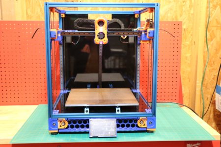
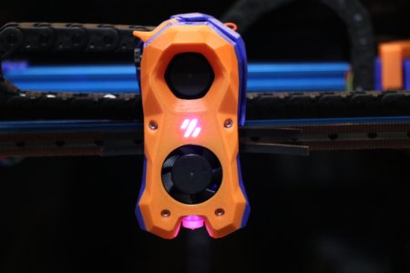
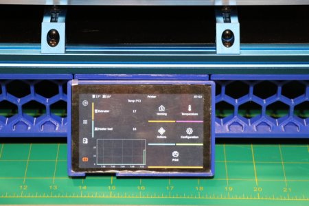
Fixed (not solved) my LED issue by replacing the 1-piece Stealthburner PCB with 2-piece Stealthburner PCB. Maybe the data trace on the 1-piece was broken...not sure, but anyways they now work. Installed skirts and a BTT PITFT50 V1.1 touch screen. Installed KlipperScreen and installed back panel as well. Display works except for the touch feature. Been Googling but so far no solution found. I guess I'll wait to install rest of the panels after I resolve the touch screen issue...


Coyote
Well-known member
After installing the two side panels I decided to add a Pi Cam to the build chamber. I had a unused one on the shelf so I printed a mount and installed the cam. I placed it in the lower front right
corner...later I may replace the Pi Cam with Logitech Webcam I have setting on the shelf...here I am piddling around while my Voron is screaming for me to hurry up and finish her...
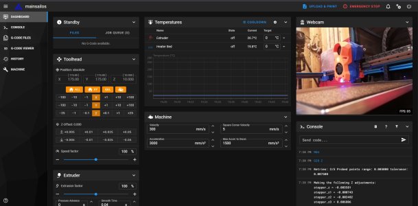
corner...later I may replace the Pi Cam with Logitech Webcam I have setting on the shelf...here I am piddling around while my Voron is screaming for me to hurry up and finish her...

austintylerdean
New member
Did you pull off all the jumpers before you started wiring the control board? That seems to be a common mishap with users of the Octopus board at least... Hope you get to the bottom of it!well crap...I'm having extruder issues...received an error when I tried to extrude filament...may be a wiring or steeper issue not sure...the reported error is "TMC 'extruder' reports error: DRV_STATUS: 000f00e0..."
Coyote
Well-known member
yep...thanksDid you pull off all the jumpers before you started wiring the control board? That seems to be a common mishap with users of the Octopus board at least... Hope you get to the bottom of it!
Coyote
Well-known member
son of a motherless goat...two problems...
First, as I suspected because of some testing with a Nema 17 plugged into the PCB socket, my steeper wiring harness had two lines crossed at the Octopus plug. Damn I tripled check with a multimeter and still screwed it up...argghhh...
Second, as suggested by ah2049 in another thread, I had a bad crimp with the JST-PH plug on the Nema 14...again damn because I called myself double checking the crimps before installing each line into the JST plug...well as I have said before... once you have suffered enough, things work...
Coyote
Well-known member
First test print done...Voron Desing Cube printed with Hatchbox PLA. Took 1 hr 14 mins...According to my calibers, the cube on all sides is within a few hundredths of a mm of 30mm. Very good first layer. No ghosting or ringing. Nice smooth and even layers and no acne. I used Simplify 3D as slicer with 0.2mm layer height. Retraction was set to 1mm at 30mm/sec. Used all default settings in the Simplify3D Voron 2.4 350mm profile. I still need to finish installing the rest on the panels (i.e. doors and bottom). One of my first mods will be to add a nozzle cleaner...
Plan to try PrusaSlicer and Cura later...
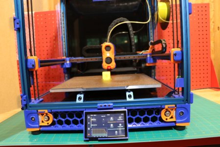
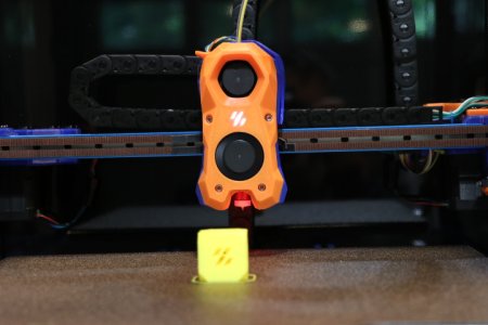
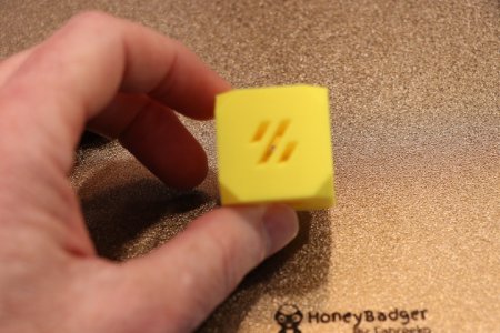
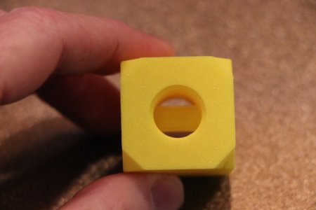
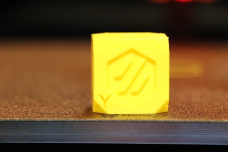
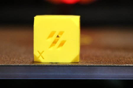
Plan to try PrusaSlicer and Cura later...


Coyote
Well-known member
LOL 'bout the camera...I do need a close up lens.Congratulations.
Now you just need to put
a camera that takes better closeups on the list, to get the fine details.
It never ends.
Do you have a nevermore air filter? I see they have a couple folks on etsy making them.
I don't have any exhaust, yet. The printer is sitting on my workbench in the garage besides orders don't bother me...I love the smell of ABS in the morning...it smells like victory...
Coyote
Well-known member
Second print was this so called torture test which the Voron handled just find...no stringing, overhangs are really good and it's fast. I haven't even tweaked the slicer profile yet and it is almost twice as fast as my Prusa MK3, the secand fastest printer I have. When it's working, which it is not at the moment, my fastest is my Anycubic Predator delta. I'm a very happy camper with this printer...
I've added a nozzle cleaner so it cleans the nozzle before each print. I need to finish the panels so I try some ABS filament and officially finish this beast...
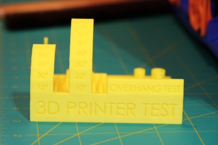
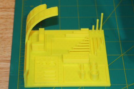
I've added a nozzle cleaner so it cleans the nozzle before each print. I need to finish the panels so I try some ABS filament and officially finish this beast...


Similar threads
- Replies
- 40
- Views
- 9K

