What's new
VORON Design

Register a free account today to become a member! Once signed in, you'll be able to participate on this site by adding your own topics and posts, as well as connect with other members!

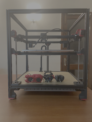
Self Sourced Voron Trident 350 - Yet Another India Build

I’ve parked the toolhead assembly for some time due to the struggles with the H2 V2X extruder. Dc3d was kind enough to reprint the entire lot of printed parts for H2 V2X using ASA. They seemed to be holding up better than the ABS ones until the extruder mount spontaneously snapped. May be I’m doing something wrong. Probably tightening too much. This time around I was more careful. I’m not very confident that the H2 V2X extruder assembly is not going to come apart mid print. I’ve called off the toolhead build using H2 V2X.

Page 23 of the StealthBurner Assembly Manual has this joke -
DON’T OVERTIGHTEN
Tighten until the plastic bends and cracks. Back up 2 turns, discard parts, reprint and try again.

I’ve already done that two times! :rolleyes:

I’m considering four toolhead options
(1) Fallback to stock SB + ClockWork 2 - I’ve sourced some cheap generic gears to finish the CW2. The thought of crimping and running loads of wires from MCU to the toolhead is not looking very appealing.
(2) SB + ClockWork 2 + EBB - I’ve rigged up an umbilical by wrapping a piano wire and the 4 core wire from BTT CAN Cable in a heat shrink tube.
(3) SB + Orbiter 2 + EBB - I sourced the Orbiter 2.0. The extruder mount looked straight forward in theory. I tried it but it did not fit properly.
(4) Xol + Orbiter 2 + EBB - the Delta fans mentioned in the Xol BOM are still not readily available here. Plus I’d have to carry out mods to the Z spacers and the front idlers.

I’m inclined towards (2) as a now. Not having a working 3D printer at my disposal limits the choices.
 
I completed the A/B Motor and Belt assembly. The shipment from Biqu landed up just before Christmas up after about 2 months from order date. By that time I had already ordered a new set of 2x Nema 17 Stepper Motor 17HE19-2004S A/B motors and installed them.

I’ve installed the CNC Voron Tap Sensor V2.1. I had a potential clearance issue on the left side of the gantry where it looked very close to the extruders for the belt to pass through. I struggled with the issue for some time. De-racking the gantry by loosening the bolts on the D Aluminium extrusion as in Solving Gantry Racking video seems to have solved it. I struggled with the belts as I had cut them too close and there is not much spare length at the ends.


VT350-1.png
 
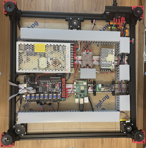
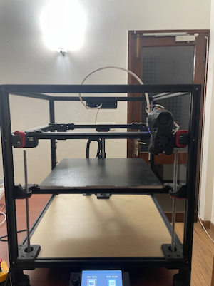
I’ve partially completed WIRING section of the assembly manual. I did discover some errors in the wiring diagram that I had created. I’ll update it at the end of the build. I used 1m cable duct chopped up in 6 sections (2x 380mm, 4x 60mm) to conceal the wiring. I could have done with a little longer duct. But I’m happy with the outcome. The motors are disconnected. It’s just enough to do the first power-on.

VT350-3.png
 
Software installation is partially complete.
  • Raspberry Pi 4B is up with Klipper, Mainsail (and fluidd as well)
  • BTT Octopus Pro is flashed and is visible in Pi.
  • U2C is visible in Pi as a device
  • EBB 36 is flashed with Katapult. I need to hook it to the umbilical and flash the Klipper on it.
Login results from Pi after first power-on. Fingers crossed - all boards are working as expected!

1735316111306.png
 
I’ve parked the toolhead assembly for some time due to the struggles with the H2 V2X extruder. Dc3d was kind enough to reprint the entire lot of printed parts for H2 V2X using ASA. They seemed to be holding up better than the ABS ones until the extruder mount spontaneously snapped. May be I’m doing something wrong. Probably tightening too much. This time around I was more careful. I’m not very confident that the H2 V2X extruder assembly is not going to come apart mid print. I’ve called off the toolhead build using H2 V2X.

Page 23 of the StealthBurner Assembly Manual has this joke -


I’ve already done that two times! :rolleyes:

I’m considering four toolhead options
(1) Fallback to stock SB + ClockWork 2 - I’ve sourced some cheap generic gears to finish the CW2. The thought of crimping and running loads of wires from MCU to the toolhead is not looking very appealing.
(2) SB + ClockWork 2 + EBB - I’ve rigged up an umbilical by wrapping a piano wire and the 4 core wire from BTT CAN Cable in a heat shrink tube.
(3) SB + Orbiter 2 + EBB - I sourced the Orbiter 2.0. The extruder mount looked straight forward in theory. I tried it but it did not fit properly.
(4) Xol + Orbiter 2 + EBB - the Delta fans mentioned in the Xol BOM are still not readily available here. Plus I’d have to carry out mods to the Z spacers and the front idlers.

I’m inclined towards (2) as a now. Not having a working 3D printer at my disposal limits the choices.
I finally figured out why I was having issues with the toolhead assembly.

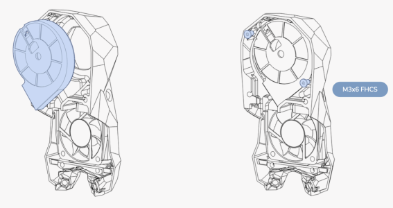
StealthBurner Assembly Manual says.
FAN PREPARATION
Remove the front of the 5015 fan. Clip off and file down the stock mounting ears.
There’s a trimming jig STL included in the release to make this task easier.
PART COOLING FAN

1735529129875.png

The front view of the 5015 is not apparent from the diagram. What I was doing wrong is after clipping the ears off, I was putting front of the 5015 fan back again before inserting it in the StealthBurner. No wonder all the extruders were not fitting properly! After some measurements and reading through the manual again, I’m happy to have located the issue. This had caused almost a month of heartache.
 
It's been a slow but steady progress so far. I completed the heavily modified "VORON STEALTHBURNER" assembly manual.

As I had started out, StealthBurner assembly was the one I was least comfortable with. So had I had modified the it to have as much pre-assembled components as possible. Also, I liked the idea of having an umbilical cord running the CAN bus which can flex in the 3 dimensional space and not having to deal with crimping and running 7+ pair of wires through a flexible cable chain between the MCU and the toolhead that flexes in only in the 2 dimensional space.

I had read enough about CAN bus and felt comfortable pulling it off as my a part of my first build. The CAN bus uses a dedicated BTT U2C V2.1 between the Raspberry Pi and the EBB. I had initialled toyed with BIQU H2 V2X All Metal Extruder for Voron. But, given the issues I had with its printed parts, I settled for Orbiter 2.0. I picked up the ChaoticLab CNC Voron TAP V2 for the Z probe.

Electronic, Electrical and some Mechanical Hardware:
ComponentElectronic HardwareEBB TerminationRemarks
Extruder Breakout BoardBTT EBB 36 CAN V1.2(G0B1)-
HotendPhaetus Rapido V2 UHF Black PT1000(HF config)Hotend 0(*), TH0Hotend 0 on EBB uses a ferrule termination. I changed the termination for the thermination to JST XH2.54 2 pin female connector. The thermistor wires have a braided teflon sleeve. I wasn't able to crimp the JST terminals on them. The problem being that the braided sleeves don't have a clean cut. There is no clean separation between the naked wires and the sleeve. After 6-7 tries, the wires were too short to terminate on the EBB. I crimped a pair of regular teflon wires and connected them to the original wires using heat-shrink butt connectors.
Part Cooling FanGDSTime GDB5015 24VFAN2The fan came with the JST XH2.54 2 pin female termination.
Hotend FanGDSTime GDB4010 24VFAN1The fan came with the JST XH2.54 2 pin female termination.
Z Probe/ Bed Leveling SensorChaoticLab CNC Voron TAP V2EndstopThe termination on the EBB is changed to JST PH2.0 5 pin female connector. Only 3 pins are required.
ExtruderOrbiter 2.0 (uses LDO-36STH20-1004AHG(XH) motor)E-MotorThe printed parts for the mod is from elcrni. I had an issue pushing the PTFE coupler into the printed part. I've just made the hole bigger as no amount of physical force I applied was enough to push the coupler into the original hole of the printed part. The termination wires for extruder motor is JST XH2.54 4 pin female connector. Termination pins are swapped to match the EBB pinouts.
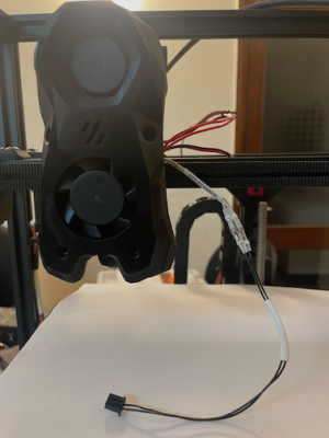
Umbilical cordBIGTREETECH EBB SB2209/SB2240 CAN V1.0 for Voron StealthBurner, Umbilical Support Spring Steel Wire, Heat Shrink TubesCAN Bus + PowerBTT CAN bus cable and a steel wire is wrapped a heat shrink tube to create the stiff umbilical cord. The connectors at the cable has to be changed to match my assembly. Two sides of the 4 pins of the CAN bus are terminated on a Molex Micro-fit 3.0 2x2 male connector of the EBB and U2C boards respectively.


This is a snap I had taken to show the heat shrink butt connector I have used for patching the regular teflon wires to the braided teflon wires of the thermistor coming from the hotend. I likes the fact there there is no physical crimping required. Heat shrinking is enough to secure the wires in place. From my reading, the thermal characteristics of the butt crimp should hold up the heated enclosure temperatures. There is a solder blob inside the butt crimp which also also hold up as the EBB also has lots of the solder on it. Theoritically, it looks good enough.

1737160712517.png
 
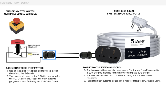
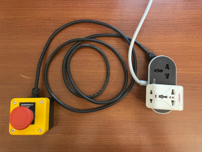
I've rigged up an emergency stop switch using components bought from Amazon.
  • Emergency Stop Switch Push Button: The top is press fitted to rest of the body. I pried open the top using a thin screw driver head.
  • Extension Cord
  • PG7 Cable Glands
  • 18 AWG 2 core electrical cable - 1 meter: Bought from a neighbourhood electrical store. This is used to connect the emergency stop switch to the extension cord.
1737161000850.png

Edit: Added pic
1737420538858.png

The main driving force behind this is the warning note I read in Voron documention sensorless homing section. I'm reproducing it here.

Note

IF YOU DO NOT READ THIS CAREFULLY AND ADJUST THINGS WHEN NEEDED YOU WILL BE SAD. IF YOU USE A PHYSICAL ENDSTOP YOU MUST CHANGE MACROS TO HOME Z TO THE ENDSTOP PIN, NOT THE MIDDLE OF THE BED. YOU HAVE BEEN WARNED!
 
Last edited:
I've started the "INITIAL STARTUP CHECKS" according to the Voron documentation. I'm using the Mainsail UI for the verification steps.

#Verification StepStatusRemarks
1Verify printer.cfg✅The only real error I had after correcting the syntax parsing errors with the printer configuration was the following.
Klipper reports: SHUTDOWN
MCU 'mcu' shutdown: ADC out of range
Sensor 'heater_bed' temperature -88.522 not in range 0.000:120.000
This generally occurs when a heater temperature exceeds its configured min_temp or max_temp.
Once the underlying issue is corrected, use the "FIRMWARE_RESTART" command to reset the firmware, reload the config, and restart the host software.
Printer is shutdown
My heat bed sensor was incorrectly terminated on the Octopus Pro MCU. After correcting the wiring, Klipper loaded the configuration files correctly.
2Verify Temperature✅Verifed that the temperature of the nozzle and bed are present and not increasing.
3Verify Heaters✅Verified that the hotend heater and bed heater are heating to 50 Celcius.
4Verify cooling fans❌Not done as the cooling fans are not installed. The skirting is planned to be printed after the printer is up and running 🤞.
5Stepper Motor Check✅All 6 motors are now verified. I had a few issues with the A and B motors which took me a good part of the day to sort out.

1. Running STEPPER_BUZZ STEPPER=stepper_x gave me the following error.
Klipper reports: SHUTDOWN
TMC 'stepper_x' reports error: DRV_STATUS: 801900e0 s2vsb=1(ShortToSupply_B!) ola=1(OpenLoad_A!) olb=1(OpenLoad_B!) cs_actual=25 stst=1
Once the underlying issue is corrected, use the "FIRMWARE_RESTART" command to reset the firmware, reload the config, and restart the host software.
Printer is shutdown
This was because I had done the termination on the MCU for LDO-42STH48-2504AC motor. I had forgotten that I had changed the motor to NEMA 17HE19-2004S due to a delayed shipment.

2. Running STEPPER_BUZZ STEPPER=stepper_y gave me the following error
Unable to read tmc uart 'stepper_y' register IFCNT
Once the underlying issue is corrected, use the "FIRMWARE_RESTART" command to reset the firmware, reload the config, and restart the host software.
Printer is shutdown
TMC driver was misaligned on the MCU. The pins were right shifted. I managed to spot it visually.
6Sensorless Endstops, XY Homing, Motor Configuration✅I took a breather and double checkied on the sensorless homing configuration before running it. I had my hand on the E-stop switch all the time! Luckily I didn't need it.
Home X and Y are working without endstops using sensorless homing.

I updated the [printer.cfg] and included the associated configuration homing.cfg as per the Voron Documentation Configuring sensorless homing guide. I tuned the driver_SGTHRSdecrementing the value from a maximum of 255 in steps of 50. I hit 0 and still no success. May be I had the X and Y switched. Still it was the same result. I finally turned the printer upside down to check the DIAG jumpers. I had forgottem to jumper them! After that I was able to tune the sensorless trigger thresholds for both X and Y with some hits and tries.

I was getting the following error even with the printer on standby.
TMC 'stepper_y' reports error: DRV_STATUS: 80190103 otpw=1(OvertempWarning!) ot=1(OvertempError!) t120=1 cs_actual=25 stst=1
Once the underlying issue is corrected, use the "FIRMWARE_RESTART" command to reset the firmware, reload the config, and restart the host software.
Printer is shutdown
I've reduced the run_current from 1.4A to 1.1A. I'm not seeing the issue after that so far.

Edit #1: Updated for check #6 and reformatted the table.
 
Last edited:
fantastic documentation. keep sharing your build progression.
Its great to see such a detailed log which would definitely assist future Indian Voron builds.
 
Last edited:
fantastic documentation. keep sharing your build progression.
Its great to see such a detailed log which would definitely assist future Indian Voron builds.
Thanks your your encouragement @sanketss84. Your posts have gotten me started me started on this journey. I've been tied up with work. Hence, not much progress on the build. Also, I wanted to re-crimp the CAN bus umbilical. I think the Molex Micro-fit 3.0 female crimps that I have are not meant for thicker gauge wires (probably AWG20). I've ordered some that go up to AWG20.
 
Top